
|
|
Forum Index : Windmills : custom made neo magnets
| Page 1 of 2 |
|||||
| Author | Message | ||||
imsmooth Senior Member Joined: 07/02/2008 Location: United StatesPosts: 214 |
I am having a Chinese company make N45 neo magnets for the F&P. They are going to be 30.5mm x 11mm x 5mm slanted 11.537deg (6mm offset horizontally), and they are going to be curved to match the curvature of the rotor. I am putting my order in soon so if anyone is interested I can tell you how much it is for the pieces plus the shipping. |
||||
martinjsto Senior Member Joined: 09/10/2007 Location: AustraliaPosts: 149 |
let me know once you have a price please im in perth WA i think you already have my address. cheers martin free power for all McAlinden WA |
||||
| imsmooth Senior Member Joined: 07/02/2008 Location: United StatesPosts: 214 |
Martin, Right now the 30.59mm x 11mm x 5mm, N45 are $1.4 a piece. Shipping is $65 to the USA. I don't know what it would be to Australia or if they would split the shipment. I am working on getting the quote for the same shape with the ARC. If I got the first quote right it is about $2.5 a piece plus a setup charge of $160 to lay out the design on computer. The $160 will probably get cut in half if both of us get them. I read about the warpage you described. Do you think 5mm or 4mm would have the warpage your 6mm magnets produced? |
||||
| martinjsto Senior Member Joined: 09/10/2007 Location: AustraliaPosts: 149 |
the magnets are from aussiemagnets.com.au there Chemical composition: Nd2Fe14B. 6mm i will try to respond to this tread from now on. i have ground the magnets 1/2mm and the stator 1/2mm to try to reduce the warping but to no effect thats not saying the 5 or 4 mm wont fix the problem just dont know weather its the hub or the clearance yet, the brake drum should tell the story. im still working on the design so any help from you will be apreciated. i will gladly help with the layout charge but obviosly want to get something that will work so experimenting first could save us both $ thanks for your help m8 martin free power for all McAlinden WA |
||||
| imsmooth Senior Member Joined: 07/02/2008 Location: United StatesPosts: 214 |
I am going to put an order in one or two days. If you are interested in the ARCS I can 1. get quotes from them for yours and mine. 2. get quote for shipping to Australia What thickness would you want? I don't know if 4mm or 5mm is better. I was going to use N42 as anything more might be too strong. I am having them to match the radius of 130.2mm. If you are interested and I get the quote you can send the money through Western Union or paypal. |
||||
| imsmooth Senior Member Joined: 07/02/2008 Location: United StatesPosts: 214 |
Here is the quote: Size: R130.2xr125.4x4.84�x30.59x11.537� (as per your drawings, the thickness will be 4.8mm) For 30 North and 30 South pieces it is $2.21/pc There is a setup fee of $160 because of the curving. (I can split this in half with you). The express fee to Australia or the USA is $90.00 These are N42 magnets, 4.8mm thick. They are slanted to reduce cogging by 11.537 degrees and are about 31mm long. They are curved to fit the curvature of the rotor. An 11mm piece will equal 4.84 degrees of the rotor circumference. If you are interested you need to let me know right away. I can give you their Western Union address and you can send them the funds. I have not seen them and am not 100% sure they will fit right. They should, but I have to hope this company does the job right. I am going to pay them tomorrow. Jonathan |
||||
| martinjsto Senior Member Joined: 09/10/2007 Location: AustraliaPosts: 149 |
thanks jonathan, i dont have the funds together yet as i have been out of work this week. it might be better for me to get the company details off you so i can order when im ready. i will send you 50% of the setup fee but again i cannot untill i get the next lot of work in. if you would rather, i will buy direct off you. sory to mees around abit but i have to fund these projects myself and cannot use funds from family budget. let me know your decision. martin free power for all McAlinden WA |
||||
| imsmooth Senior Member Joined: 07/02/2008 Location: United StatesPosts: 214 |
No problem. I ordered mine today. I hope the dimensions are right. If they work out for me and you are ready in the future let me know. I can order them for you and have them shipped directly to you. |
||||
| imsmooth Senior Member Joined: 07/02/2008 Location: United StatesPosts: 214 |
I just got my magnets. They are slanted to reduce cogging and they are curved to exactly fit the curvatur of the F&P rotor. There is no clicking or bad seating; it is perfect. I am hoping the tight fit adds to the strength of the rotor so there is no warpage. Here are some pictures. It is subtle, but note how the second picture slightly curves up on the righthand side off of the table. There is an arc incorporated into the magnet design. 
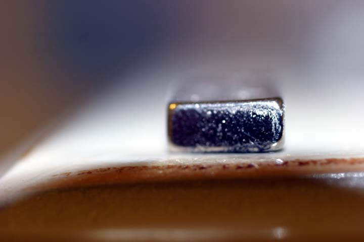
If these work out would anyone be interested in purchasing some for their F&Ps? I can have more fabricated. |
||||
| brucedownunder2 Guru Joined: 14/09/2005 Location: AustraliaPosts: 1548 |
Yes,please .. let me know asap Thank you Bruce Bushboy |
||||
| imsmooth Senior Member Joined: 07/02/2008 Location: United StatesPosts: 214 |
If they work as I hope I will get a price and a shipping cost to Australia for you. I will post pictures as I rebuild the rotor. |
||||
| Gizmo Admin Group Joined: 05/06/2004 Location: AustraliaPosts: 5186 |
Hi imsmooth. Nice! If they work out, and your interrested, you can resell them on the site. I can set up a page where you can show how to fit them, etc, the results you obtained, and how to order the magnets from yourself. Just an idea, if they work I figure a few people will want to try them. Glenn The best time to plant a tree was twenty years ago, the second best time is right now. JAQ |
||||
| imsmooth Senior Member Joined: 07/02/2008 Location: United StatesPosts: 214 |
Thanks Glenn. I don't want to offer them if they don't work. I will keep a photo log of my progress. Again, my biggest fear is that the rotor warps. I designed them at 4.8mm to reduce the magnetic pull on that stator iron. Again, by curving with the rotor they should reinforce its strength. If there is enough of an interest I will buy a large quantity to reduce the cost per magnet. Shipping from China would be about $75 for a set of 60 (30N, 30S). I would have to work out the price per magnet depending on how many I have fabricated. Lead time was quoted as 2 weeks. |
||||
| imsmooth Senior Member Joined: 07/02/2008 Location: United StatesPosts: 214 |
Here are my updates so far... Starting the process using 3mm tile spacers plus two sheets of paper per spacing. 
Rotor ready for fiberglass sealing 
|
||||
MyCattMaxx Newbie Joined: 24/02/2008 Location: United StatesPosts: 8 |
Looking good. Thanks for pics.  |
||||
| Tinker Guru Joined: 07/11/2007 Location: AustraliaPosts: 1904 |
Re sealing magnets, has anybody tried this idea: Magnets assembled as in picture above. Hub mounted on horizontal shaft so that the shaft can be driven to rotate slowly via variable speed control. Spacers are removed and hub spun up. Resin is dripped on the spinning magnets. It will evenly disperse outwards by centrifugal force, no dam is required if there is still a lip on the open side of the hub. Keep spinning until the resin has set. I have not tried that with magnets but on some other job and it worked well enough as long as the rotating speed was fast enough to stop the resin running to the lower end. Tinker Klaus |
||||
| brucedownunder2 Guru Joined: 14/09/2005 Location: AustraliaPosts: 1548 |
Hi Klaus,, Interesting concept, be nice to see your idea work . The resin on the surface face of the magnets,,would you take this off ?? With my luck ,I'd get resin all around my workshop and the space suit ,I'd have to wear ,lol. I ,ve made 3 of these and ,using cloth backed "Gaffa" tape as a dam ,they have all come out nearly perfect. The ordinary plastic tape is a disarster,don't use it. Anyhow ,the magnets look good ,so you left those little bits of plastic around the inner circumference for ease of spacing ??. Good work Bruce Bushboy |
||||
| KiwiJohn Guru Joined: 01/12/2005 Location: New ZealandPosts: 691 |
I suppose while the rotor is still whirling in the lathe (or whatever) and the resin is liquid you could use something like a paint brush to wipe the magnet faces? I was going to say a rag but that might lead to injuries.  |
||||
| imsmooth Senior Member Joined: 07/02/2008 Location: United StatesPosts: 214 |
Well, here is the update. I sealed the rotor as follows. I put lamination paper around the outside of the hub and fixed with tape. I removed the spacers and spilled some resin into the gaps, letting it cover the magnets up to the inner lip. I let it set and rotated the rotor and poured in more resin. I repeated this process of pouring, setting, and rotating until I finished th whole rotor. This took a day. I had tried using various tapes on the inside, but the surface wasn't smooth and I couldn't tell if I was making too thick of a coating. I used a file to shave off fiberglass resin where it was too thick. Here is the picture. 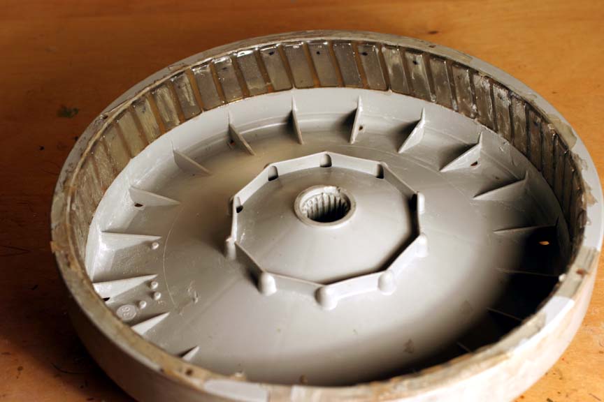
Now, I loaded it onto the stator hoping it wouldn't warp. The end result - absolutely no warpage. As I hoped, the perfect fit of the magnets reinforces the strength of the rotor. Also, the thickness gives a little more distance from the iron core, reducing the pull. Using formulas, I calculated the the pull in pounds for the ceramic magnets is 0.6lbs; the pull-force of the neos is 6.83lbs. We have an x11 difference in pull. However, despite the added force, the rotor kept its shape with no special effort on my part! My next concern was cogging. With the ceramics on a virgin stator I need to use 13v to get the rotor moving. It takes 3v alone to get the motor(mover) to start moving if nothing is attached to the shaft. After rounding the iron cores I needed 7v. One would expect the neos to require more voltage to move the rotor since the pull is x11 greater. However, with the slanted insertion the necessary voltage to get the rotor moving was still 7v. I could feel some cogging if I didn't have the circuit completed. If I connected the generator to my load the cogging was very slight, and hardly noticeable. I considered this a success, too. I have super powerful magnets on the rotor, but the starting voltage is the same as the ceramics. Here are some data that I got. I am limited to how fast I can spin the rotor as my mover is only 3/4HP. Load 110ohms RPM Vceramic Wceramic Vneo Wneo 120xxxxxxxxxxxx30xxxxxxxxxxxxxx50 180xx88xxxxxxxx54xxxxxxxx150xxx170 200xx100xxxxxxx75xxxxxxxx170xxx205 I changed my load to 75ohms and only tested the neos RPM Vneo Wneo 60...50.....30 130..100....135 150..115....172 160..120....192 It looks like I am getting 2w per RPM. In summary, the magnets were easy to install using 3mm tile spacers. I'm sure there is a better way to seal them, but this too wasn't a big pain. The rotor is completely stable without any warpage. Cogging is minimal. I would like to know what everyone thinks. |
||||
| brucedownunder2 Guru Joined: 14/09/2005 Location: AustraliaPosts: 1548 |
A nice job ,,I like that idea of just setting a few at a time --you have complete control over the resin ,,,when things go wrong ,it's a mess !! stiffness,,sounds like you have got that monkey off your back-good. O/P,,, I'll wait and see some "up-there" results. Could you again tell me what size blades ? A dual with ,say, 12-13 foot blades would really give some power ,and start up in light winds. The angle of the magnets--- they look quite "angled" in the photographs,, I tend to make this angle slight, too much may waste some energy,I'm thinking.... Anyhow,,you are doing a nice job ,wishing you success Bruce Bushboy |
||||
| Page 1 of 2 |
|||||
| The Back Shed's forum code is written, and hosted, in Australia. | © JAQ Software 2026 |
