
|
|
Forum Index : Electronics : Poidas "Inverter Software Control" Topic.
| Author | Message | ||||
| rogerdw Guru Joined: 22/10/2019 Location: AustraliaPosts: 792 |
Those are seriously impressive photos Wiseguy. I love the framework for your Eltek units ... looks bomb proof ... and the pcb transformers are brilliant too. I looked at the photo a heap of times before I realised that it is not a 20 cent piece .. but a 5 cent piece. That is tiny. Are they RM6 cores ... and 350kHz ... I wanna see the drive circuitry around that. I'm also trying to work out how you're going to mount them. I wondered about a slot through a pcb, the Tx on its edge ... and one pad soldered on top and one on the bottom ... but somehow I don't think that's what you've got in mind. Cheers, Roger Cheers, Roger |
||||
| Warpspeed Guru Joined: 09/08/2007 Location: AustraliaPosts: 4406 |
Not really, if its functioning properly it will work fine. ĀIf something fails, all bets are off. Even voltage feedback can fail open circuit, and the control system will then ramp up the output to absolute maximum. If extreme output accuracy is a requirement, slow feedback could be added to a feedforward system, and is sometimes done. This could take the form of a slow self learning algorithm. An example of that might be the engine management system in your car. The basic system uses many different engine sensors, rpm, load, temperature and so on fed into a series of lookup tables to create outputs for fuel delivery and ignition timing. Its a very fast acting feed forward system. There is usually no feedback required for it to work. However, there may be a lambda sensor in the exhaust that can be used to make very small changes to correct for engine wear or the gradual drift of engine sensor outputs over time. That is a form of very slow feedback which gradually modifies the much faster main feedforward control system. In a past life I used to work for both Invertech and Solar Basic as a power electronics design engineer, designing commercial inverters amongst many other things. None of these ideas are new or revolutionary, and not patentable, its all a prior art. All the control system concepts date back to about the 1930's and its all pretty well understood. Its all jolly good fun and interesting, and in retirement if I can pass on a few tips and ideas that others find useful that is reward enough for me. Edited 2019-12-01 23:59 by Warpspeed Cheers, ĀTony. |
||||
| BenandAmber Guru Joined: 16/02/2019 Location: United StatesPosts: 961 |
Thanks Warpspeed even though simple to some of you still over my head I have purchased my son a soldering station he is 12 I've been looking for and saving small circuits to put together For some Hands-On learning for him and me I have chosen a small audio amplifier circuit and a ghost finding circuit so far Maybe these small simple circus will help him and I both gain more understanding of electronics be warned i am good parrot but Dumber than a box of rocks |
||||
| wiseguy Guru Joined: 21/06/2018 Location: AustraliaPosts: 990 |
Roger, glad you liked the 2 pics & you are right the Eltek frame is bomb proof lol made it out of stuff I had lying around - somewhat over engineered but cost nothing except for some time - it has a motley collection of screws that I will update as soon as I get a couple of boxes of different length 4mm countersunks. The cores are RM6 ungapped, I will post a schematic and mounting pics as soon as I get back to my workshop. I am not at my normal location again until the weekend. The mounting is using right angle dual row 0.1" pin header and there are two mounting options - your method would work but I suggest using the el cheapo prototype service they would slug you for the slots ! If you want any second hand Flatpack 2s tested & working there is an ebay source @ $60 ea + freight. Tony thanks for posting a good description of how it can be done. In my case software is not one of my skills & I was thinking an analogue solution to give Poida a rest. He seems to be somewhat over worked and underpaid. So I wondered about using the variac code and some analog circuitry. I was also considering using current sensing from the supply side to compensate for FET bridge/transformer etc losses, the feedforward system corrects for the supply voltage differences and the current sense tweaks for the other losses - I reckon it would be almost as good as secondary sensing - I was a bit concerned about overall stability - I am assuming this has been tried and proven in things youve already done before and stability is a non issue? If at first you dont succeed, I suggest you avoid sky diving.... Cheers Mike |
||||
| Warpspeed Guru Joined: 09/08/2007 Location: AustraliaPosts: 4406 |
Mike, Stability is a non issue because nothing is fed back. It simply can never oscillate because there is no feedback loop. The correction may be slightly imperfect giving less than optimum regulation, but it will be totally and unconditionally stable. This voltage feedforward system is well tried and proven in my own Warpverter which has been powering my home, with zero problems for one full year. It has never missed a beat. Andrew has developed his own Warpverter software using a Nano, whereas my own Warpverter is totally hardware. Both my own hardware derived feedforward, and Andrews software derived feedforward work in exactly the same way, and our two very different circuit boards are directly interchangeable with identical plugs and connectors. I have run both boards in my inverter, and Andrew has run both in his inverter. These two boards can be swapped over in less than a minute. The basic inverter functionality is identical in both, although Andrews board being a Nano has some extra added features, my more basic hardware board lacks. The way mine works, is that the incoming dc voltage is measured 25 times per second with a dual slope analog to digital converter. As suggested previously, the upper half of the measurement range goes from 00 at half scale to FF at full scale. That selects one of 256 different lookup tables, that produce all of the eight different mosfet gate driver waveforms to the inverter. As the input voltage goes up and down, different lookup tables provide the most appropriate waveforms to drive the transformer primaries. This generates a low distortion sine wave when all four transformer secondaries are added together in series. There is absolutely no feedback, nothing is connected to the secondary except the 230v load. ĀAndrews Nano has identical inverter functionality, but his is all done with magic and number crunching, instead of the five volt discrete logic I use. Exactly the same feed forward control concept would work just as well with pwm as with a stepped sine wave. The current sensing idea is something quite new, I have only thought of in the last few days and have not yet tried the idea out in hardware. It will be extremely easy to implement, and I have ordered a suitable 100 amp Hall sensor which is not going to arrive here for another three weeks at the earliest. The concept behind this, is that at the moment the +2.5v voltage reference for my analog to digital converter comes from a TL431 fixed voltage regulator. I can use a single supply 100 amp Hall sensor that runs off +5v, to measure the inverter dc input current. ĀThe Hall sensor (HSTS21) has an output of +2.5v with zero measured current, and of course the output voltage goes up and down depending on measured current direction and flow. I can connect a potentiometer between the fixed +2.5v from the TL431, and the variable +2.5v output of the Hall sensor. ĀThe wiper of the pot then provided my +2.5v dc reference voltage to the A/D converter. If the wiper is at the TL431 end, the voltage reference will be a constant +2.5v with zero correction of the inverter output voltage from input current variations. If the wiper is at the Hall sensor end of the potentiometer, the +2.5v reference to the A/D converter will vary with the inverter input current, in both magnitude AND DIRECTION. There is a subtle point about this. The A/D converter is ratiometric, so that the measured parameter (inverter input voltage correction) and the A/D reference (inverter input current correction) multiply, not simply add or subtract from each other. I should be able to tweak that pot so that the inverter output voltage can be corrected to compensate for the resistive losses in the switching bridge, and transformer windings that causes the inverter output voltage to droop under heavy load. The interesting thing about that, is that the inverter output voltage normally falls off with increasing load as expected. Ā But when reverse power is being fed from a grid tie inverter back into the battery, the inverter output voltage will rise by a similar amount due to the same resistive losses in the bridge and the transformer. When back feeding power, the Hall sensor will correct for the voltage rise, just as it corrects for the voltage droop under normal inverter load. Should be possible to find an optimum position where the inverter output impedance can be set to zero with perfect voltage regulation in either direction. Its a fairly simple idea but difficult to put into a very few clear concise words. If any of this is not clear, I will try to clarifyĀ  Edited 2019-12-03 09:17 by Warpspeed Cheers, ĀTony. |
||||
| Warpspeed Guru Joined: 09/08/2007 Location: AustraliaPosts: 4406 |
Here is a shot of my "hardware only" feed forward control board. The big chip at the top is an ICL7109 adc, the chip immediately below is a W27C020, 256K x 8 rom. Notice that the only connections to it are for the fused dc input (at the top) and all the gate driver outputs to the four inverters (along the bottom). There is no feedback or any other connection to the board. An absolute minimum of wiring is required. 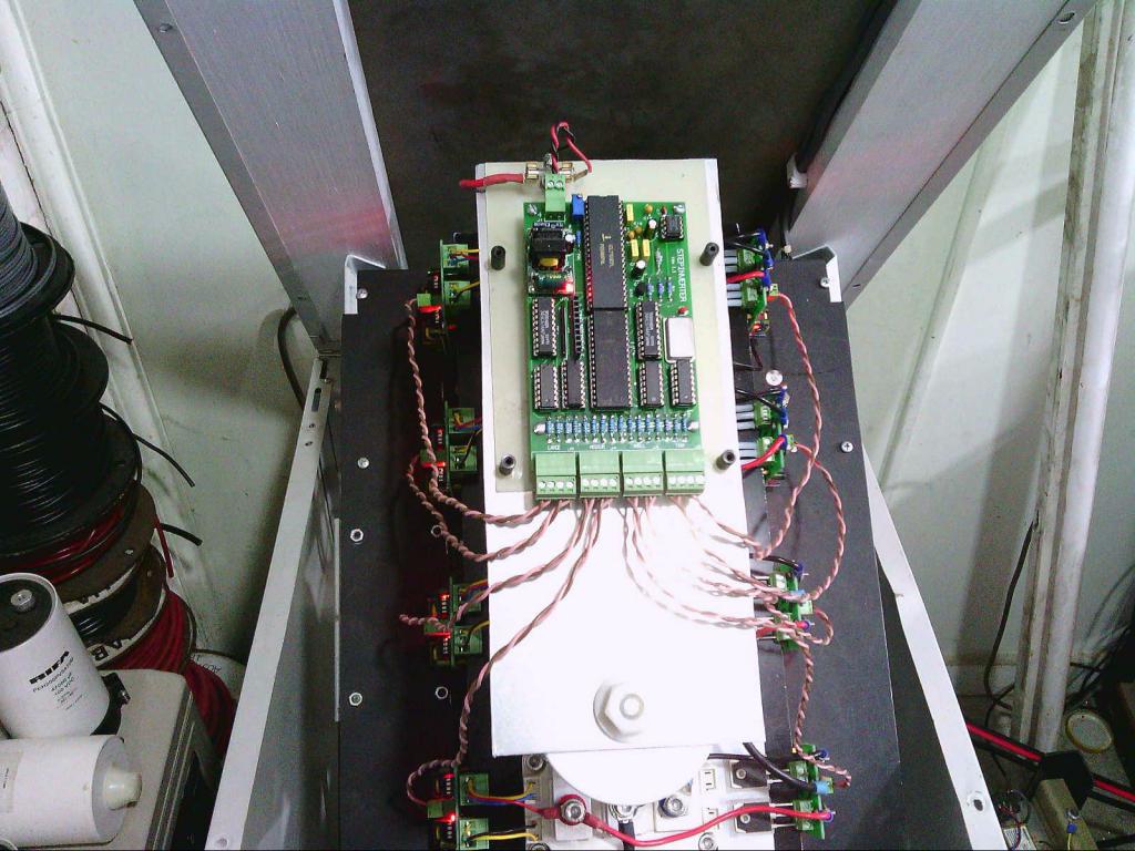 This is Andrew's Nano driven feed forward board, it plugs straight in. 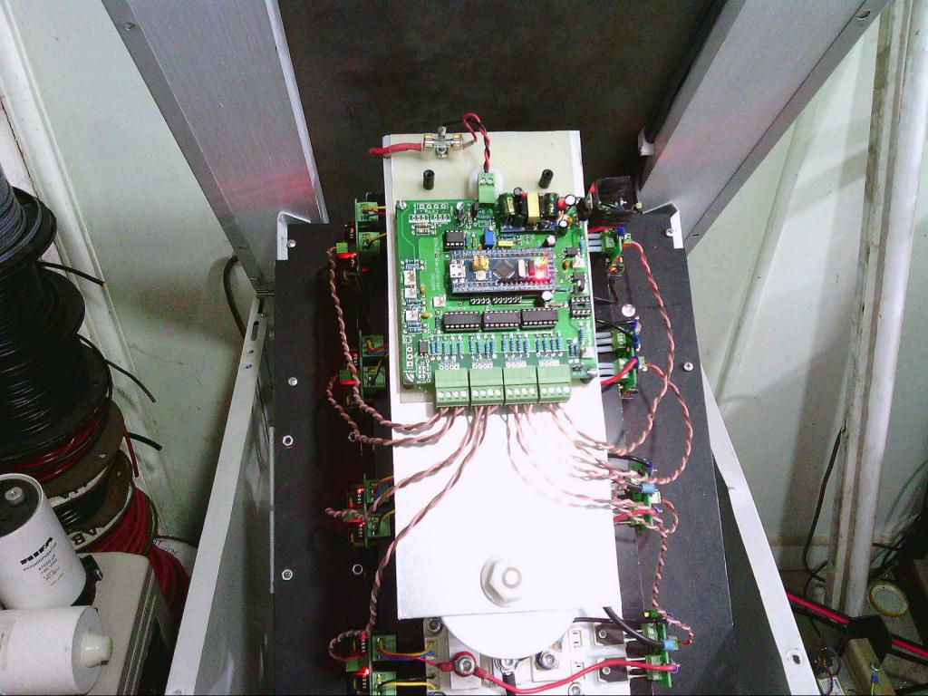 The aluminium plate has threaded plastic spacers to allow either board to fit. This inverter has been running constantly for a year and I keep swapping the two different boards back and forth occasionally. Both have absolutely identical control characteristics and its impossible to know which is in there without actually looking. 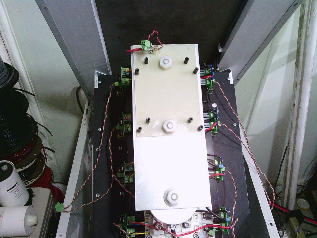 Edited 2019-12-03 09:48 by Warpspeed Cheers, ĀTony. |
||||
| wiseguy Guru Joined: 21/06/2018 Location: AustraliaPosts: 990 |
Thanks for the detailed reply again Tony, I need to articulate myself more when I post, the query about stability was directed at the current sensing compensation which I reckon is a feedback loop of sorts in that we sense current adjust the output, which affects the current which effects the output....stop I want to get off. There is no doubt in my mind that feedforward compensation for the input voltage should be unconditionally stable. If at first you dont succeed, I suggest you avoid sky diving.... Cheers Mike |
||||
| Warpspeed Guru Joined: 09/08/2007 Location: AustraliaPosts: 4406 |
Certainly a valid point Mike. If you look at this from just the current compensation aspect, the inverter is going to have a finite output impedance, made up by all of the various cumulative small resistances in the transformer, mosfets, and wiring. As we know, that is where our voltage droop comes from. Now if we use input current sensing to cancel out some of that, the inverter output impedance will be reduced, theoretically down to zero should be possible. If we overcompensate so that the inverter has an overall negative output impedance, we might be in trouble. But the inverter load will add some additional positive series impedance to the inverter impedance, even if its slightly negative. Unless the overcompensation is set outrageously high, the whole thing should still remain quite stable. Anyhow, we will know for sure once my Hall effect sensor arrives in three weeks or so. Cheers, ĀTony. |
||||
| Warpspeed Guru Joined: 09/08/2007 Location: AustraliaPosts: 4406 |
Just received an e-mail from Klaus a few minutes ago. He has fitted this experimental input current sensing feed forward system to his Warpverter and it works exactly as we had both hoped. All it took was two extra components, a Hall sensor, and a 1K potentiometer. With about 3Kw inverter load switched in, he can adjust the compensation potentiometer to have the exact same output voltage as at zero load. Absolutely no voltage droop at all now, and no sign of any instability. Feed forward voltage plus current compensation is definitely worth a try with a pwm Nano inverter. Any volunteers ? Cheers, ĀTony. |
||||
plover Guru Joined: 18/04/2013 Location: AustraliaPosts: 302 |
Is the 3 kW load the maximum for the unit or just a 'decent' test load on a bigger unit. I do read the post as performance from zero to 'full load' |
||||
| Warpspeed Guru Joined: 09/08/2007 Location: AustraliaPosts: 4406 |
Klaus built it as a 7.5Kw Inverter. He is just doing some bench testing and initial messing about with it, and he did mention that he has a fan heater and a flood light he is using as convenient test loads. He has also tested it with an airconditioner and microwave oven and is feeding power back into the battery from a grid tie inverter. He is trying all kinds of things just to get a feel for what it can do and how it responds. Klaus is particularly impressed by the clean sine wave that never distorts no matter what kind of horrible loads or inrush currents he connects. If the voltage does not change with a zero to 3Kw step change, its hardly likely to vary much with a much higher load. Cheers, ĀTony. |
||||
| poida Guru Joined: 02/02/2017 Location: AustraliaPosts: 1387 |
Wiseguy, here is a modified version of the variac code, with a slow start and slow stop function. It takes about 2.5 seconds to ramp up to the set point when pin D8 is pulled high. And when D8 is pulled low, slow stop will execute taking the output gradually down to zero. I thought you might find this useful in your development of the inverter electronic control loop. nano_variac_slow_start_stop.ino.zip wronger than a phone book full of wrong phone numbers |
||||
| wiseguy Guru Joined: 21/06/2018 Location: AustraliaPosts: 990 |
Thanks a heap Poida I'm currently snowed under with preliminary new house stuff but will be back onto it in a week or so. Is it just a slight change to the pin definitions to change the Vadjust to be on the same as the Vfb sense pin of the nano-verter, without breaking anything ? It will be easier to hack my current board if this change is ok. If at first you dont succeed, I suggest you avoid sky diving.... Cheers Mike |
||||
| poida Guru Joined: 02/02/2017 Location: AustraliaPosts: 1387 |
easy change. Tell me which pin has the output of the potentiometer and I will alter it to suit. Take no time at all. wronger than a phone book full of wrong phone numbers |
||||
| wiseguy Guru Joined: 21/06/2018 Location: AustraliaPosts: 990 |
Pin 19 would be great thank you !  If at first you dont succeed, I suggest you avoid sky diving.... Cheers Mike |
||||
| BenandAmber Guru Joined: 16/02/2019 Location: United StatesPosts: 961 |
I was very curious about this feed-forward system that's why I asked you about it to begin with you said any volunteers on pwm I'm sure that probably meant a volunteer that knew what they was doing Not a monkey see monkey do type of volunteer I have several hall effect sensors if you can use any of them I could maybe try to overnight them to you let me know if you're interested This offer is not Limited to hall effect sensors it also is not limited just to warpspeed Anything that I have that I am not using I will donate for free to anyone on here If it is a very heavy item then the person receiving might have to pay part or full shipping This is the very least I can do to help out I have received a very large amount from this form ( that means from all of you guys) I have contributed very little It would make me very happy to help in any way that I can be warned i am good parrot but Dumber than a box of rocks |
||||
| poida Guru Joined: 02/02/2017 Location: AustraliaPosts: 1387 |
that would be the pin marked "A0" nano_variac_slow_start_stop_a0.ino.zip wronger than a phone book full of wrong phone numbers |
||||
