
|
|
Forum Index : Electronics : Tinkers warpinverter
| Page 1 of 3 |
|||||
| Author | Message | ||||
| Tinker Guru Joined: 07/11/2007 Location: AustraliaPosts: 1904 |
As I have had some progress with my warpinverter project its time I keep you all posted. I started this project by winding the big transformer but that turned out in a disaster So I tackled this project from the electronic side first  . .PCB's were first on the list, here is my version of the half bridge board: 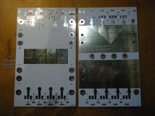 Top and bottom side are shown. There are 4 identical boards required. Each can accommodate 4 individual half bridges or be linked to fewer parallel bridges. Since 2oz PCB's are expensive it made sense to have smaller boards, as one has to order 5 boards minimum anyway. So I have a spare board now. Here is one board populated with its few parts, top & bottom side are shown: 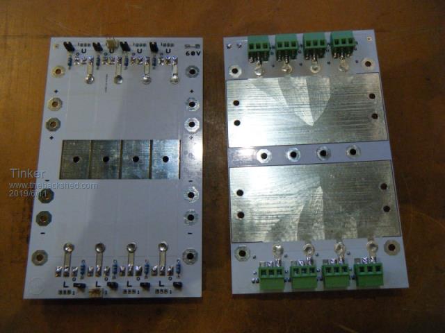 And here is a close up showing warpspeed's clever method of boosting narrow tracks with the help of solder lugs: 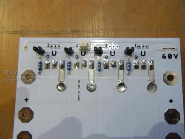 Now I have added the50x3mm alu bus bars for the power rails on the bottom side: 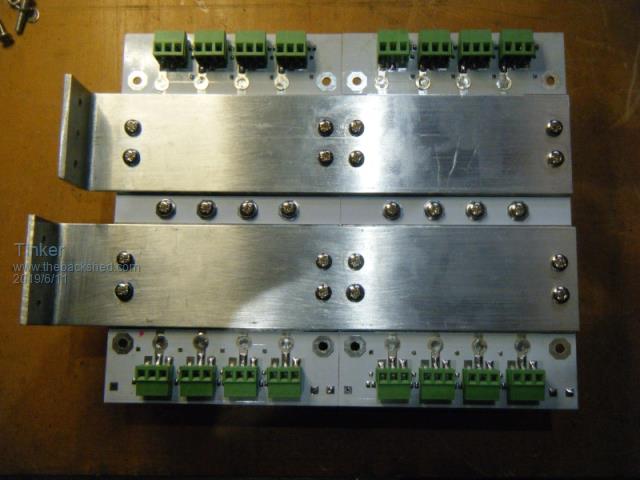 On top are tinned copper bus bars for the transformer connection. The sequence of the drivers is, from left to right: No. 3 transformer, No. 4 transformer, No. 2 transformer, No. 1 transformer. No.1 is the biggest transformer and has 4 x 4 parallel mosfets. No. 2 transformer has 4 x 2 parallel mosfets. 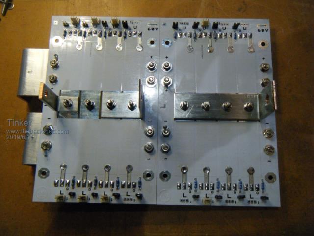 So that shows two of the half bridge boards, the other two are identical. Now I also need some driver boards: 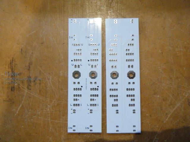 Top & bottom side shown, I made these boards as double half bridge drivers for space reasons which can be seen on the next pictures. Here is the full complement of driver boards for my warpinverter: 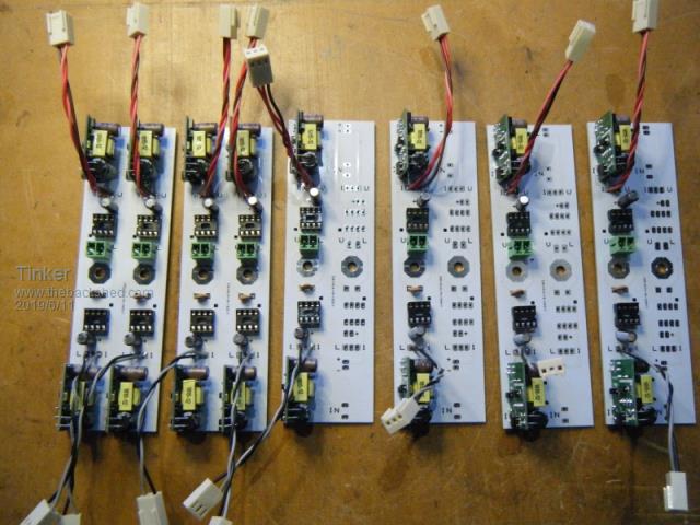 Some are fully populated with parts, on others only half the board is used. The next picture shows why, The power boards have a simple way to parallel Mosfets by inserting a header shunt to link the gates and by bridging VS tracks with a busbar. 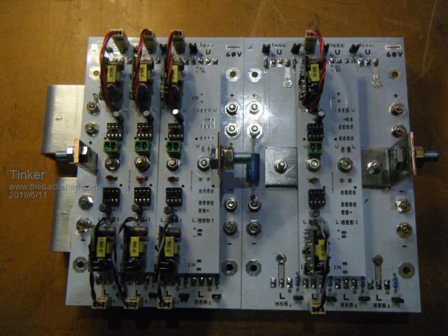 So that were the PCB's I designed. There is another, the control board, which is warp's design and shown on the final pics below. Now the lot was assembled to two identical size heat sinks (one 3KW Aerosharp heat sink cut exactly in half). First is a picture looking from the bottom end, showing the 120mm fan: 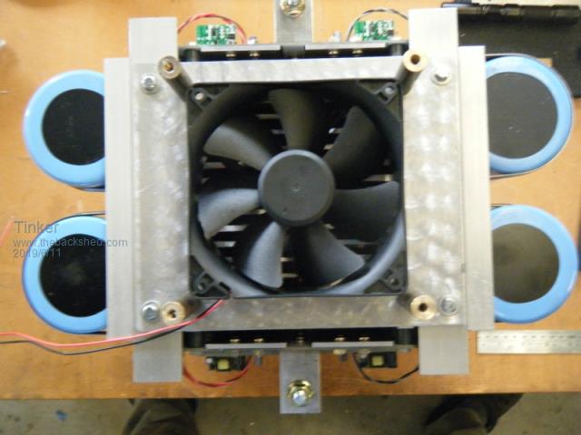 And to connect all those busbars together we have 'busbar junction' at the top view:  BTW, I used 'Alminox' to prevent the mating alu surfaces from oxydising. Now a side view to show how it all fits together. The view from the other side is identical: 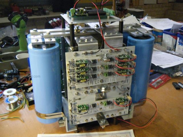 Here is a close up of the boards: 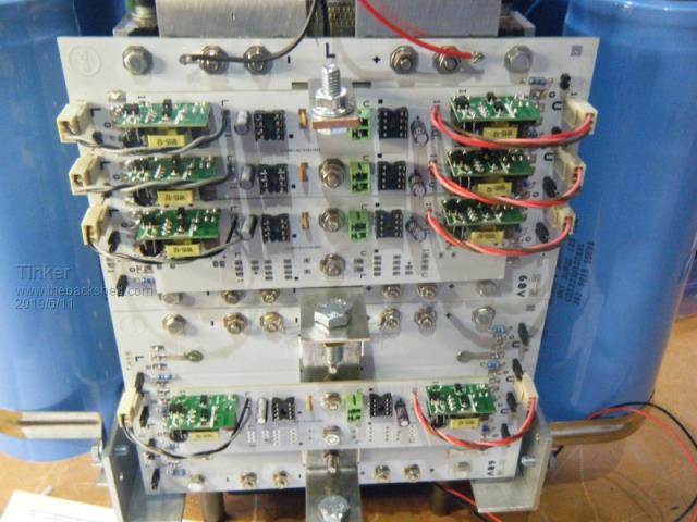 And a top view with the control board in place: 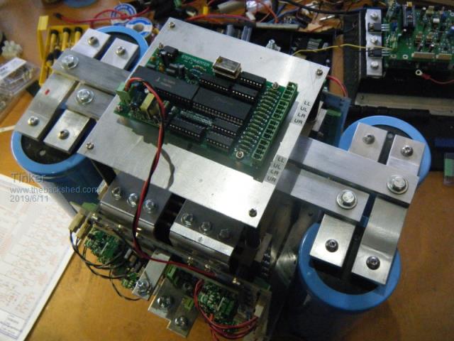 And lastly a picture to compare the size of those gigantic capacitors with a Pepsi can: 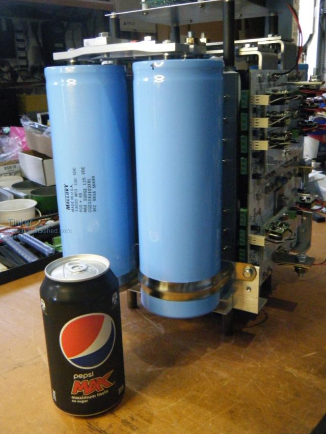 Still to make are the gate drive leads, have to get some suitable wire first. Also, no IC'd or mosfets are installed as yet, that's easy later on as they are on sockets or into terminals. Then I'll have a break to catch up with other projects and get a start winding those 4 transformers, for which I finally managed to round up all the toroid cores. Klaus |
||||
renewableMark Guru Joined: 09/12/2017 Location: AustraliaPosts: 1678 |
Just a tip Klaus, I wouldn't go taking that on a plane, it really looks sinister. Nice work, how many KW do you plan it to run? Cheers Caveman Mark Off grid eastern Melb |
||||
mackoffgrid Guru Joined: 13/03/2017 Location: AustraliaPosts: 460 |
 Looks top notch Klaus. The white PCBs and all that shiny aluminium looks fantastic. cheers Andrew |
||||
| Tinker Guru Joined: 07/11/2007 Location: AustraliaPosts: 1904 |
Very unlikely Mark, At a guess it will weigh well north of 50kg when its finished. But it does look like a satellite with rocket boosters eh?  The big transformer is rated at 5KW so +1/3rd, +1/9th, +1/27th should make ~7KW total, more than enough for my peak use. For the long haul its limited by 20A secondary rating so about 5Kw. How is your warpinverter coming along? Klaus |
||||
| Warpspeed Guru Joined: 09/08/2007 Location: AustraliaPosts: 4406 |
That is an incredible piece of very professional engineering Klaus  The idea of paralleling up individual half bridges for the higher power stages using identical circuit boards is really clever. All very well thought through and compact, yet still all very readily accessible, and it should be especially easy to work on. The layout of the capacitors is excellent, as it allows for various physical sizes and the number of capacitors to be changed for anyone that wishes to copy the basic layout, without having to redesign the circuit boards to suit. Also plenty of room there for the larger 100 x 100mm future Nano driver board Cheers, �Tony. |
||||
| mackoffgrid Guru Joined: 13/03/2017 Location: AustraliaPosts: 460 |
+1 Yes, the modular half bridges are particularly clever. |
||||
| renewableMark Guru Joined: 09/12/2017 Location: AustraliaPosts: 1678 |
Almost finished No3 torroid, No4 shouldn't be much work. Still need to do primaries on 1&2. Work for me is almost non existent this time of year and rely on what I made in summer, so it's a bit hard to justify buying bits right now. Wife gets cranky easily  Cheers Caveman Mark Off grid eastern Melb |
||||
| Tinker Guru Joined: 07/11/2007 Location: AustraliaPosts: 1904 |
Thank you for the kind comments, I had fun designing this project. Now I'll have to wait until I got some transformers ready to find out if it actually works .Sorry to hear about your lack of work Mark (what do you do?). I retired from paid work 12 years ago. At work I was never as busy as I'm now, messing about in the shed. No wife to stop me buying parts either . Klaus |
||||
| BenandAmber Guru Joined: 16/02/2019 Location: United StatesPosts: 961 |
Well I for one think Tinkers just showing off I don't think Electronics care if they're beautifully thought out and perfectly positioned You know I'm just teasing Tinker that is absolutely awesome Like I said before on here you guys make this an art form You are a artist and this is a beautiful piece of art !!!! I am absolutely amazed at what you guys do be warned i am good parrot but Dumber than a box of rocks |
||||
| Warpspeed Guru Joined: 09/08/2007 Location: AustraliaPosts: 4406 |
Klaus, all four inverters are basically identical, and all four transformers are designed to handle 50Hz, and so all the transformer primaries are interchangeable. Any transformer can be driven by any inverter with any of the four drive waveforms. So basically you can plug transformers 2, 3, and 4 into inverter outputs 1, 2, and 3 and see a correct 27 step waveform, but of one third of the correct final output voltage. Or you can just run it without the largest transformer and see something that looks a bit like unipolar PWM drive, two half sine waves but telescoped into each other. It will give you a sneak preview, and a very good feel for how it all works. If any of the phasing ends up being wrong, either upper/lower drive to the inverters or drive to the transformers, no harm will occur. The output waveform just goes a bit strange, but its easy to just swap things back around until the waveforms all add together with the correct relationships. So don't be afraid to have a play, and give it a try even without having all the transformers. Cheers, �Tony. |
||||
| mackoffgrid Guru Joined: 13/03/2017 Location: AustraliaPosts: 460 |
Guys, I agree with Tony about playing around, observing and learning with the Warpverter. My Warpverter consists of 40 Mosfets and in over 6 months of playing around with it I have managed to blow just 5 or 6 fets (all explainable). It all pretty much worked like clock-work. |
||||
| renewableMark Guru Joined: 09/12/2017 Location: AustraliaPosts: 1678 |
Nah I'm fine, business is quite good in summer, just need to be careful and put it aside while it's flowing freely. Winter in Melbourne effects lots of businesses the same, just a seasonal thing, I hate the bloody rain.  Less solar too so need twice as many friggin panels Less solar too so need twice as many friggin panels Get back to work and finish that machine. Cheers Caveman Mark Off grid eastern Melb |
||||
| mackoffgrid Guru Joined: 13/03/2017 Location: AustraliaPosts: 460 |
Guys, I'm was about a week or so away from starting a topic on my Warpverter build. I was hoping this would be helpful to others as many other threads has been helpful to me. But as Klaus is progressing so fast I thought I'd bring up one issue I was going to talk about. My large transformer is based on the 3kW Aerosharp transformer with the outside winding stripped off. I'm using the inner winding as it is for my secondary. I then used the wire I stripped off as the primary (~38mm2) using the Madness / oztules idea. This first inverter is a 26.5v inverter so my turns ratio is just under 9. I found that I was getting a large capacitive current spike, > 60 amps, which would create voltage spikes on the output at low load. My turns ratio makes this worse by a factor of four compared to you guys who are doing 48V. A choke sorts this out nicely. About 50uH seems to be a good value for my transformer. I will also be fitting a choke on my 2nd transformer. These chokes have a different function to the Ozinverter, it wont affect standby current, it's not to filter HF - it just smooths out the the capacitive current spike. Tony has mentioned that the way the secondary wound tightly to the large toroid core may make the capacitance so much higher. Below is one method of reducing winding to core capacitance. 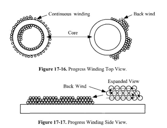 Transformer & inductor design handbook ch17 I am really poor at winding transformers and chokes but you guys are more talented than I, and may want to give this a whirl. I have photos of spikes and waveforms but I just wanted to bring this to you attention before it's too late. Cheers Andrew |
||||
| renewableMark Guru Joined: 09/12/2017 Location: AustraliaPosts: 1678 |
Interesting, Warp calculated the turns for mine, the No1 is a double 3kw core. 128 sec 25 primaries, so close to 5 to 1. Wonder If mine will have the same issue. Where did you put the choke? Cheers Caveman Mark Off grid eastern Melb |
||||
| mackoffgrid Guru Joined: 13/03/2017 Location: AustraliaPosts: 460 |
Double Core, what a rippa  Yes, your flux density is a bit lower (and better) than mine. Because of my aversion to winding transformers, I used the existing winding and let that set my volts per turn. Mine will be fine and my standby power is also good, but a lower flux density would have lowered that current spike I'm getting. Cheers Andrew |
||||
| renewableMark Guru Joined: 09/12/2017 Location: AustraliaPosts: 1678 |
I think it was Poida that pulled apart a commercial machine that had the torroid wound like that. Yeah it was, found the pic here Cheers Caveman Mark Off grid eastern Melb |
||||
| Warpspeed Guru Joined: 09/08/2007 Location: AustraliaPosts: 4406 |
Your turns ratio is fine Mark. Andrew is using a radically different minimum design voltage (26.5v) to your 44.0v minimum design voltage. Both secondaries will of course be the same 225v. Andrew and I have discussed this problem, it appears that winding the first full single layer onto an extra large steel steel toroidal core can have a relatively high capacitance down to the core. This capacitance has to be charged and discharged as the 225v square wave voltage on the secondary very abruptly switches. It only happens on the edges of the 50Hz square wave and its only a relatively tiny amount of energy involved, so its not going to effect idling power or efficiency. But it might generate some voltage spikes or ringing on the output waveform. I have never had this problem for two reasons. My large transformer uses E/I laminations and a fiberglass bobbin which is about 2.5mm thick greatly diminishes the capacitance down to the core. The first layer of the secondary is also comparatively narrow, with many built up layers layers on top. A toroid has just the one very wide winding for the first secondary layer. Also, my minimum design voltage is 90v which gives me a required transformer ratio of only 2.5 which makes any current spike in the primary vanishingly small, if its even there at all... Its not really a serious issue, and not really a problem. As Andrew says, a very small choke will effectively limit the rate of current rise during the transitions. Only the largest toroid is involved. The smaller toroids have fewer secondary turns and a lower secondary voltage, and the ratios are also a lot lower. The larger toroid will also have a more gutsy inverter driving it, and any very fast and narrow current spike is not going to be large enough to be dangerous. So at this stage its just an interesting phenomena we have noticed, rather than something to be afraid of. If you do end up with spikes or ringing on the edges of your square waves, a very small non critical choke should fix it. I have never actually seen this effect myself on any of my own previous inverters. Its only when the largest toriod becomes truly enormous we might need to start taking the increased winding capacitance a little more seriously. Its all part of the perils of scaling things up Cheers, �Tony. |
||||
| mackoffgrid Guru Joined: 13/03/2017 Location: AustraliaPosts: 460 |
Your ratio of 5:1 gives you better odds than mine at 9:1. Its a N-squared relationship. (of reflected capacitance). It is simple to test for once you assemble your machine - I'll go into that deeper with photos later. Just put the choke in series with one of legs of the primary of the main transformer. The choke will need to carry the primary current. Cheers Andrew |
||||
| Tinker Guru Joined: 07/11/2007 Location: AustraliaPosts: 1904 |
Hmmmmm, chokes? Well, I have just a little experience winding them should one be required .I also use a double stack core for No.1 transformer but its made from 2 x 2.5KW aerosharp toroids. All my toroids were completely unwound of the original windings and I'll start a new secondary & primary. That capacitance effect is something I was unaware of, however, I have a 6mm plywood cheekplate with rounded edges on each core top & bottom so that will space half of each winding turn off the core. Hand winding a torodial core is tricky enough if one wants a neat job. Including 'back winding' looks like a challenge to me, especially if the available hole area is on the tight side. Have fun with that Andrew .Tony, thanks for the offer of information regarding testing the thing. I certainly will have questions about that when the time comes but just now that info might be too soon to be retained by my leaking grey matter. Klaus |
||||
| Tinker Guru Joined: 07/11/2007 Location: AustraliaPosts: 1904 |
Well, yes and no . I try to build my projects better than one bought from a shop (I do not have to make a profit).It gives me satisfaction if something turns out looking respectable rather than like a rats nest. A well thought out layout is also easier to service and I have always built with this in mind. A tip Ben, take pride in your work and try to do every new project better than the last one you did. Its a learning process, mistakes are a great teacher Klaus |
||||
| Page 1 of 3 |
|||||
