
|
|
Forum Index : Electronics : Allans Mad-Inverter Project
| Page 1 of 5 |
|||||
| Author | Message | ||||
| shallowal Regular Member Joined: 26/07/2018 Location: AustraliaPosts: 58 |
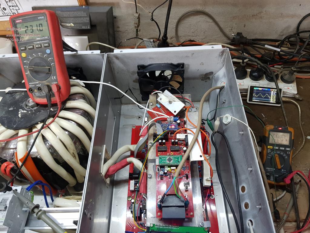
Thought I would join the party (somewhat late I think) and get my inverter project underway. So far I have the transformer wound and the boards built, and am somewhat through testing the board functions and am stuck on a couple of problems that I would like some help with. I have set up a test rig with a 12V supply to the Arduino, a (nominal!) 48V supply to the power board, and an AC supply to the Voltage feedback circuitry through a Variac. I have no FETs or caps on the power board and the transformer is not connected. 1. The only way I could get the EG8010 chip to provide a continuous output was to add a large cap to the voltage sense inputs. Without the cap I get a 1.5v ripple on pin 13 (VFB). With the cap there is no ripple and the EGS8010 doesnt complain about under-voltage. I checked that all the components including the 4.7uf and 0.1uf caps are soldered correctly and connecting to the signal path. 2. In this config I get nice 50Hz square wave signals out to the IR2110 on pins 10 and 12. I also get a nice 50Hz square wave from the IR2110 on pins 1, but Pins 5 and 7 have approx 16-17 volts fixed. On the PWR BD I can see the totem-pole drivers on the ground side of the bridge delivering around 17v to the Gate's of the FETS as per the output of the 2110's, but on the high voltage (48V) side I have 16.5V fixed on both collectors of the Totem Pole pair. Any suggestions, or help as to how it is supposed to work?. I have a reasonable understanding of electronics, but I am missing a couple of key points here I think.  Allan Allan |
||||
| Warpspeed Guru Joined: 09/08/2007 Location: AustraliaPosts: 4406 |
Suggest you get the EG8010 datasheet if you don't already have it: https://www.lz2gl.com/data/power-inverter-3kw/eg8010_datasheet_en.pdf 1/ pin 13 should be +3v when the ac on the secondary is 230v (or whatever its supposed to be). A small amount of ripple should be o/k because the EGS8010 just takes a single fast voltage sample reading, and if its +3v at the instant of measurement its happy. It will then attempt to ramp the output up or down to achieve the +3v goal. If after three seconds the output is below +2.75v the EGS8010 shuts down. If after 0.3 seconds the voltage is above 3.15v it also shuts down. If pin 13 is deliberately held at very close to +3v, either from your variac, or a dc supply, the EGS8010 should be able to run continuously. But a lot of ripple on pin 13 might trip shutdown if either of the above undervoltage or overvoltage conditions are met. 2/ The IR2110 circuit is probably o/k, but the high side part of it cannot get any power until the mosfets are connected up. There is a voltage pump circuit that uses a diode that supplies power to pin 7 to the capacitor between pins 7 and 6. That capacitor cannot charge up until the lower mosfet turns on. As the lower mosfet is not yet there, that cannot happen. So the low side drives should both be working, but both high side gate drivers are probably not working, but should when all the mosfets are fitted. Cheers, ĀTony. |
||||
| shallowal Regular Member Joined: 26/07/2018 Location: AustraliaPosts: 58 |
Thanks Tony, I had already studied the EG8010 datasheet and was monitoring the VFB line which is why I decided to smooth it with additional capacitance. I have followed a number of the other threads regarding the Ozinverter and had not noted anything about modifying the standard cct around this function, hence my question of why mine wont work without the additional capacitance. I gather from your comment that it shouldnt matter that I have the additional capacitance there. The low side drivers seem to be working, but I couldnt understand how the high side works. The voltage pump idea sounds like the key and I've just discovered that I've installed the wrong caps here :). Thank you. Allan |
||||
| BenandAmber Guru Joined: 16/02/2019 Location: United StatesPosts: 961 |
Pics of your build please be warned i am good parrot but Dumber than a box of rocks |
||||
| Warpspeed Guru Joined: 09/08/2007 Location: AustraliaPosts: 4406 |
That voltage pump circuit is a bit tricky, and its caught a lot of people, including myself at times. If you fit the mosfets it should then run without the transformer connected, and you should then be able to see the full 48v output swing on either side of the bridge. I have no idea what is going on with the electrolytic on the voltage feedback  ??? ???If you tie that down with too many microfarads its going to slow down the feedback which would not be good. So its a bit of a compromise between too slow, and having the feedback go "wild". Cheers, ĀTony. |
||||
| shallowal Regular Member Joined: 26/07/2018 Location: AustraliaPosts: 58 |
Thanks Tony, Yep!, With the FETs installed I get the full voltage swing and can now see the high frequency output which I couldnt see before. I reduced the Cap to 100uf, any less than that and the EG8010 wouldnt stabilise. I'll revisit it when I get everything assembled into a final setup. Allan |
||||
| Warpspeed Guru Joined: 09/08/2007 Location: AustraliaPosts: 4406 |
Sounds like you are well on your way, great stuff  Cheers, ĀTony. |
||||
| shallowal Regular Member Joined: 26/07/2018 Location: AustraliaPosts: 58 |
It's not a build as yet, but will post something when becomes something. Allan |
||||
| BenandAmber Guru Joined: 16/02/2019 Location: United StatesPosts: 961 |
If there is any parts I can donate or help you with please let me know be warned i am good parrot but Dumber than a box of rocks |
||||
| shallowal Regular Member Joined: 26/07/2018 Location: AustraliaPosts: 58 |
That's very kind of you to offer, thankyou. I think I have all the parts or can get them locally without trouble. The next major issue is sourcing a battery, to either try out the inverter or for permanent use. I'm about to run up the inverter with my 40(+)v power supply but I doubt that I'll have enough to run a light bulb never mind anything with a 'K' in front of it. Allan Allan |
||||
| shallowal Regular Member Joined: 26/07/2018 Location: AustraliaPosts: 58 |
 Well, Whaddya know. It actually works!!!.  I connected a 60w light bulb OK and the configuration is just 4 FET's and no capacitors. Woohoo!!! Allan Allan |
||||
| Warpspeed Guru Joined: 09/08/2007 Location: AustraliaPosts: 4406 |
Excellent results Allan Before you start adding the big electrolytic capacitors and more mofets, I strongly recommend you fit a choke in series with the primary to reduce the stresses on the mosfets. Do you still have the original iron cored Inspire chokes that came with those stainless steel boxes ? Cheers, ĀTony. |
||||
| johnmc Senior Member Joined: 21/01/2011 Location: AustraliaPosts: 282 |
Well Done. Thanks for the pictures. Cheers john johnmc |
||||
| shallowal Regular Member Joined: 26/07/2018 Location: AustraliaPosts: 58 |
I have three turns around one of the Aerosharp chokes in series with the toroid on the high frequency side already. I'll take a picture. Allan 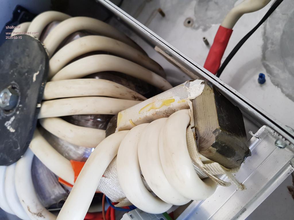 Edited 2020-02-15 12:01 by shallowal Allan |
||||
| shallowal Regular Member Joined: 26/07/2018 Location: AustraliaPosts: 58 |
Or, does that count as 4 turns? Allan Allan |
||||
Revlac Guru Joined: 31/12/2016 Location: AustraliaPosts: 961 |
Well Done Allan, Can you make a note of the idle current at this stage and again after all the fets are in place, be interesting to see if there is any change. Looks good. Cheers Aaron Cheers Aaron Off The Grid |
||||
| Warpspeed Guru Joined: 09/08/2007 Location: AustraliaPosts: 4406 |
Yes its four turns. You can get away with using thinner wire on the choke, because the wire length in the choke is very short. The transformer primary needs the thicker wire to reduce losses and heating. It would be better with more turns, and if you can stack two sets of choke cores, even better still. Its a case of more is always better. A 1.5mm to 2.0mm gap spacer might be about right. There is no substitute for testing a choke, but my gut tells me that should come pretty close. Cheers, ĀTony. |
||||
| shallowal Regular Member Joined: 26/07/2018 Location: AustraliaPosts: 58 |
Do you mean stacked on top of each other with a 2mm gap and then the wire wrapped around the combined toroid?. 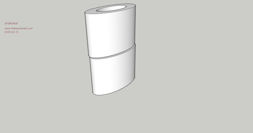 Allan Allan |
||||
| Warpspeed Guru Joined: 09/08/2007 Location: AustraliaPosts: 4406 |
There are a two different ways to stack two pairs of U cores: 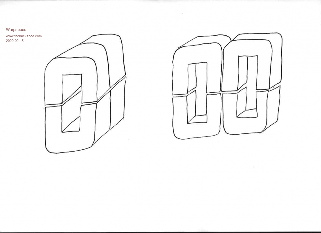 Both work and will have the same characteristics with the same air gap, but there is one notable difference. The mean length of turn is different. The cores themselves are not rectangular in cross section, and if you stack two end to end the length of copper wire per turn is longer. If you stack two cores side by side, the core cross section in the middle becomes rectangular, or almost rectangular, creating a shorter turn length. 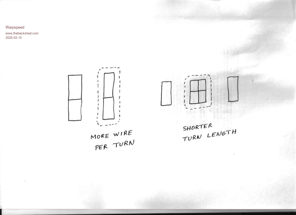 This is all more theoretical than practical for our purposes, so in your case, do whichever way seems easiest and most natural. If I remember correctly, the combined window area of two Aerosharp cores produces a hole 70mm x 20mm. ĀIn theory 14 turns of 10mm outside diameter round wire should fit through that, and it is possible, but only just. Twelve turns might be a more realistic expectation. 10mm over the plastic with about 8mm diameter of copper is 4mm x 4mm x 3.142 = 50mm squared. that will run warm at 100 amps dc, but will work very well. About a 1.5mm to 2mm spacer should put you in the 150uH and 150 amps just before saturation range. Edited 2020-02-15 17:45 by Warpspeed Cheers, ĀTony. |
||||
| shallowal Regular Member Joined: 26/07/2018 Location: AustraliaPosts: 58 |
I wish I had , it would have been a sensible thing to do. Unfortunately I didnt and by the time I had seen your post I had already added the capacitors and extra FETs. Allan Allan |
||||
| Page 1 of 5 |
|||||
