
|
|
Forum Index : Electronics : 3 phase inverter for AC induction and servo motors
| Author | Message | ||||
| wiseguy Guru Joined: 21/06/2018 Location: AustraliaPosts: 995 |
Peter, I have been doing some testing on various 1-5 2.5KW Toroids I have lying around. At 240V their magnetising power consumptions were 9.7W, 9.3W, 7.8W & 7.2W. A similar small transformer for the voltage feedback was 1W. So if we took worst case at 9.7W (+1W for feedback) and multiply the result by 3 we should have ~ 32W of magnetising (idling current), so for 66W of input power it looks like the IGBTs/chokes are consuming the remaining ~ 34W of power. An IGBT doesn't have an on resistance, it is part FET part transistor, its the transistor part that makes it sturdy but also gives them a saturation voltage of typically 1.5V - 2V. �So the IGBTs are consuming around ~ 6W of the remaining power with no switching losses. If the concept is to run from 48V then IGBT's will be rather lossy at larger power levels. For instance if you were to run an average power of 4kW three phase �it would be that each Leg of the chopper will have around 27A of current but it will be x 2 IGBTs so the losses for each leg will be of the order of 50W per leg. �Using 2 x HY5608 Mosfets per LEG with their 1.5milliohm on resistance will generate ~ 2W per LEG a saving of ~ 145W of power/heat. (these were just rough calculations) Congrats on making a 3 phase inverter a relatively simple reality. Can you post your rough schematic (one leg is sufficient) with part numbers, will help reduce the guessing. By the way, the TV1013-1M 2mA voltage transformers you are familiar with are an excellent way to help reduce noise in the feedback voltage. If you use 2 x 100K resistors, one on either side of the input winding then @ 240V you have around 1.2mA. So either passively or actively on their secondary winding you can get a suitable relatively low noise feedback voltage. Edited 2022-07-26 18:24 by wiseguy If at first you dont succeed, I suggest you avoid sky diving.... Cheers Mike |
||||
| poida Guru Joined: 02/02/2017 Location: AustraliaPosts: 1388 |
PWM signals are produced by a STM32F401 micro 3.3V supply is taken from the Black Pill module The 60uH and 1uF filter combo is likely to be changed in future HLK-PM15 are isolated 15V supplies that work down below 45V We could use one only for the 3 LOW side legs of the 3 half bridges but Haxby built the board to use one for each. 3 x half bridge drives 3 x transformers 3 x Vfb 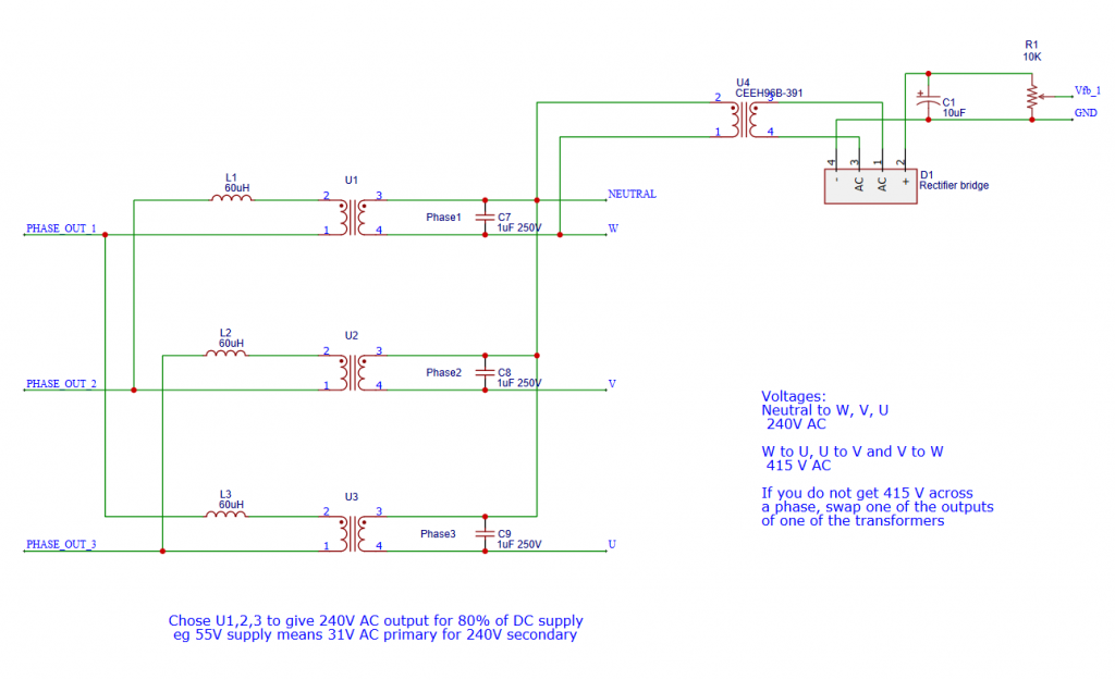 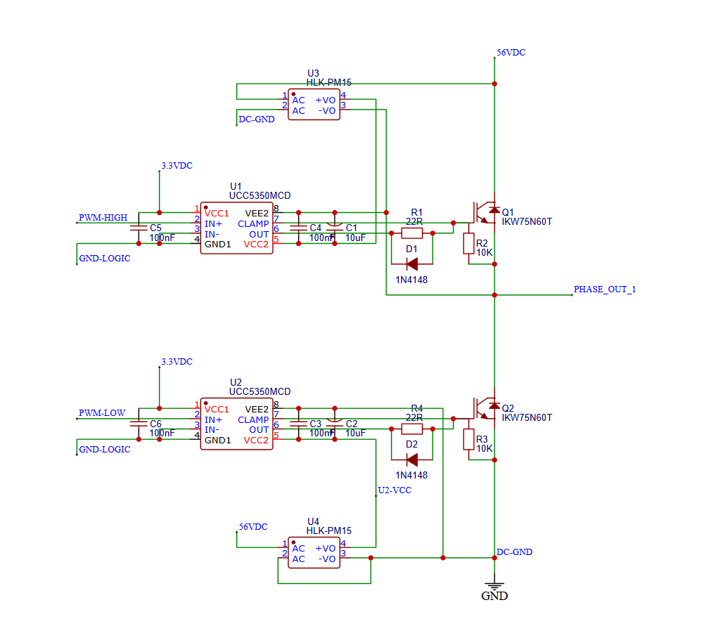 wronger than a phone book full of wrong phone numbers |
||||
| poida Guru Joined: 02/02/2017 Location: AustraliaPosts: 1388 |
Testing things is most educational for me. So far the testing has had all 3 phases driven by the same power factor. This is not ideal but probably quite workable in most cases since it's up to us to ensure the 3 phase load is balanced and we could make sure. But it would be nice if the inverter would re-balance things to some degree automatically. Today I have all 3 phases with EMI filtered Vfb inputs. I altered the code to individually control each phase via it's Vfb. And it's not stable at all. Probably one phase is backfeeding into the inverter and so increasing the other 2 phases. And all 3 phases are doing this in some random manner. Re-reading the EG8030 info I notice the reference design has non-smoothed Vfb inputs AND these are sampled at particular times different for each phase. That is, the Vfb signals do not have smoothing capacitors. OK, I can do this. But is it needed. The datasheet says the chip can be used in a few different ways 1 - voltage of all 3 phases controlled by Vadj pin and open loop control (this is like my first tests) and EG says it's easy to do. Well, it was as a matter of fact. 2 - voltage of all 3 controlled by average of 3 Vfb and closed loop control to maintain a setpoint. Also look for > 10% voltage difference between phases and shutdown with error if seen. This works with isolating transformers. 3 - all 3 phases controlled individually by their Vfb, with closed loop control maintaining to a setpoint. EG says it's rarely used. It takes output direct from the 3 half bridges, that is, no transformers! If I want to go with the 3rd way (and it's not for isolated transformer builds) it's not nice. see this: 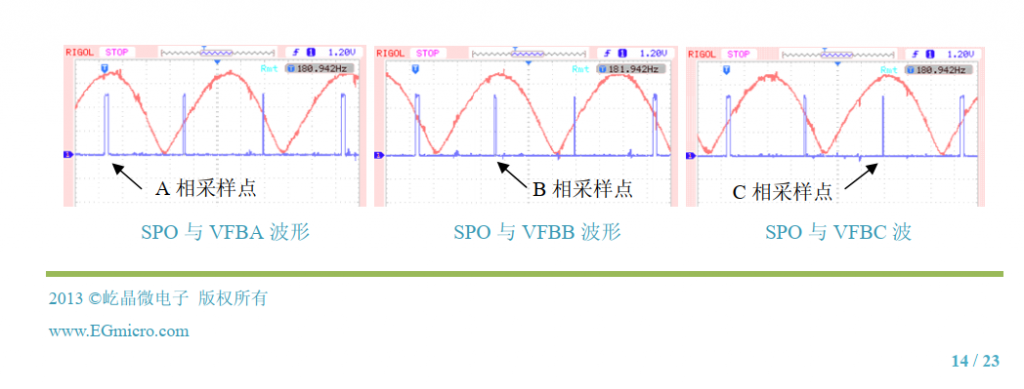 The Red traces are rectified AC, what comes out of the bridge rectifier. The Blue trace is some constant time reference The 3 graphs are phase A, B and C rectified voltages phase A is sampled at a time near it's peak, B at it's peak, C at it's peak. The sample times are unique for each phase. back to the drawing board and write some new code. This is the fun part of a project for me - unexpected results requiring a rethink and recode. Edited 2022-07-27 14:26 by poida wronger than a phone book full of wrong phone numbers |
||||
| poida Guru Joined: 02/02/2017 Location: AustraliaPosts: 1388 |
I got the idle power down a bit. First, I tried to drive 2 phases a little higher voltage than the remaining phase. To do this the PWM amplitude is increased a bit, maybe 2% more than normal. This did not work in a way I could understand. It seems phases are effected by each other. Increase the output of one of the half bridges and the AC voltages do strange things on all 3 phases. Time to forget about individual trims for each phase. So I took one turn off the primary of the phase that was lowest in output voltage and now they all are within 2 V. P1 - 240 V AC P2 - 238 P3 - 239 Idle power is lower now, 1.1 A at 52.4 V or 57W with a 540uF cap on the supply it's 1.0 at 52.6V or 53W wronger than a phone book full of wrong phone numbers |
||||
Revlac Guru Joined: 31/12/2016 Location: AustraliaPosts: 961 |
I thought that would help a little bit. Ignore the following if its not helpful. Looking at some small 3 phase generators most of them do voltage sensing from 1 phase, leaving the others to flout around depending on which phase it was connected to, some had a separate winding for voltage sensing, also had a large voltage difference due to the resistance in the winding on the small generators when uneven loads are placed on other phases. The big generator 250KVA, I thought it might have voltage sensing on all phases, but not exactly, not on the one I checked, It has the MX341 AVR according to the diagram it still uses 1 phase voltage sensing, and some other trickery that I'm not sure about. How much difference is the voltage on each phase when it is all regulated from one phase? I expect it would not be much under load due to toroid winding being fairly ridged....bit too early to ask this, so leave it to later. That sounds easy enough to do.  Cheers Aaron Off The Grid |
||||
| poida Guru Joined: 02/02/2017 Location: AustraliaPosts: 1388 |
I finally hooked up the 1/2 hp motor, and ran it with the 2 Amp limited power supply. I gradually increased PWM duty width from zero to maximum.. It did not rotate and that is OK. Not enough grunt But was not happy, rotating a bit one way then the other and could not just get going. I then put the 2kW Eltek on it, good for 40 Amps And the motor did not rotate as I increased PWM. It half rotated, then backwards then whatever. It was not happy at all. off with the motor and back on the 2A supply and now I can not get 415V output, only about 1/3 of that before the power supply shows it's shorting somewhere. I broke it. Now I have replaced the IGBTs with HY5110 100V FETs and the 415V AC has returned. Less power needed too, 55.5V at 0.8 Amps is 44 W Now, let's see if it can spin a motor... It does! https://youtu.be/8TDI1vHvULE about 0.65A at 55V And no damage to anything so far. The heatsink is far cooler now. wronger than a phone book full of wrong phone numbers |
||||
| poida Guru Joined: 02/02/2017 Location: AustraliaPosts: 1388 |
This might help you work out the wiring of the delta wired priamaries It's easy to get it wrong and you only get 240V phase to phase and not 415V All you need to do is swap the phase's primary 180 degrees. Here is a properly wired 3 phase waveform: the single phase voltages measured with respect to some common voltage (the neutral in a star connection maybe) 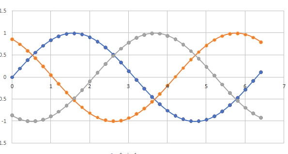 and the phase to phase voltages 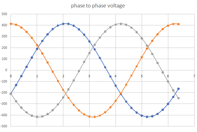 now, I alter the timing of the Orange phase by adding 180 degrees. This is as if I swapped the primary winding terminals. 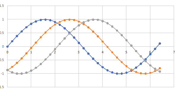 The 3 phases are now NOT evenly split apart by 120 degrees. and here are the phase to phase voltages 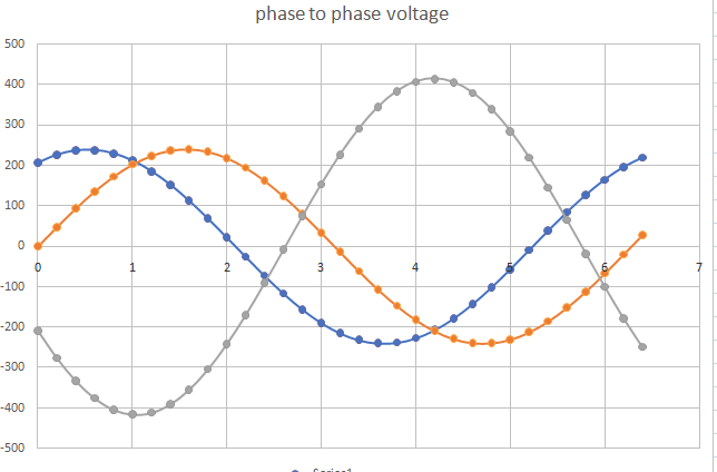 wronger than a phone book full of wrong phone numbers |
||||
Haxby Guru Joined: 07/07/2008 Location: AustraliaPosts: 418 |
Great work! |
||||
| poida Guru Joined: 02/02/2017 Location: AustraliaPosts: 1388 |
Testing with the AC motor as load is still disappointing. I can get it to spin but only with DC supply current less than about 2 Amps This is when the PWM duty width is only about 1/3 of max output voltage Any more than this and things go badly. No idea why since I have no idea what is happening. I suspect that it's related to current flowing into one or all of the 3 outputs of the power board. Recall there must be 3 outputs, one each for the 3 half bridge drive sections. I blew one or more of the IGBTs doing this test. The FETs seem to be more robust and don't blow when I run it to the power level that initiates the bad situation. Are IGBTs weak in reverse current conduction compared with FETs? But then the IGBTs were of how to put this, Chinese origin and so they could be dodgy or counterfeit or even pre-broken There is a whole lot of stuff going on with the current flows of this contraption on the bench. I assumed I could do something interesting with moderate power levels but once the output voltage gets to about 100V phase to phase the motor runs very rough and I hear bad things from the transformers and large DC supply current spikes. Maybe it's just EMI on the logic level gate drive signals. AS the output increases, so does the EMI and this may be stuffing up the carefully built PWM signals going into the gate drive IC inputs. I can see this is going to take a lot of time to debug. wronger than a phone book full of wrong phone numbers |
||||
| poida Guru Joined: 02/02/2017 Location: AustraliaPosts: 1388 |
The poor running of the motor when nearing even 1/2 415V remains a problem. After pulling it all down and taking it home, I thought "maybe the motor is wired delta when I need star..what is the voltage for delta and star anyway?" The motor is rated at 240V when wired delta and 415 when star wired. This info is from the info plate attached to the side of the motor. It was wired delta. So that is why it ran badly when I got past 240V or so. I was running or trying to run it at 415V. Must be. I reassembled the inverter at home, and rewired the motor to star wiring, good for 415V and tried again. At around 250V things go badly with loud humming, clicks and what-not and I quickly back off the PWM duty to zero, wondering if I blew the FETS finally this time. So it's not the motor's voltage setting (and it's winding inductance) that is the primary cause. Or is it. I have read a little on ferroresonance and I suspect this might be it. I can raise the output voltage gradually to some point and it goes bad. Sometime I raise it quicker to nearly that voltage and it goes bad quicker. This has the characteristic of resonant behavior. Adding a lossy element in the 3 phases circuit can help, as electronic eng people know but I am fast getting to the point where I will leave this be and get on with life. I could buy a few 1 Ohm 20W resistors and put one in series with each phase on the output, to dampen the oscillations. It might work. The test setup is purely inductor and capacitors. And the secondary and primary winding DC resistance which is not-very-much. This is a high Q LC tank and it wants to oscillate. Maybe it's time to wait for a clue to arrive from somewhere and get on with other things (making sure the 11 channel watering system for the garden works before Summer heat and dry arrives, for one thing) wronger than a phone book full of wrong phone numbers |
||||
| Haxby Guru Joined: 07/07/2008 Location: AustraliaPosts: 418 |
This brings back memories of when I was playing with my warpverter. Everything was working well up to around 200v but things started to buzz and pop when going higher in voltage. A good resource for VFDs is the openinverter forum. Particularly anything by Damien Maguire. For what it's worth, All I can suggest is to simultaneously measure as many points in the circuit as possible. Are you measuring the current per phase? Do you have a way of measuring the motor shaft angle and correlating that to the current? |
||||
| Revlac Guru Joined: 31/12/2016 Location: AustraliaPosts: 961 |
I don't remember reading about any problems with the megaverter, but still a work in progress, I still don't have 3 toroids the same size but after some looking around, I have not seen any 3 phase transformers (in use) that use Toroids, at least not around locally that I could have a look at, there have been some on the www and that they can be made to order. I was getting curious and looking for reasons why not, for a start the price to make one for 3 phase using toroids was quite high, not a problem for those of us that can reuse a second hand toroidal transformers. Something that has been bugging me for a long time, the 3 phase welder transformer, the flux on one leg has a path to the other legs and some flux leakage and is somewhat necessary to have flux leakage (read that from somewhere) , using toroids I don't see how that happens, perhaps a steel shield over all 3 toroids, not sure about that. Also using toroids there is the usual high starting surge. This may cause some issues when trying to use for a VFD, I hope this is not the case. There is some pro's and cons here https://www.iqsdirectory.com/articles/electric-transformer/toroidal-transformer.html Other thoughts, I have some 6kw Inverter powerboards rev4: Is there any reason I can't butcher those to make up a 3 phase power board? Also been working on the garden growing food, need it now the farms are all flooded. Cheers Aaron Off The Grid |
||||
Madness Guru Joined: 08/10/2011 Location: AustraliaPosts: 2498 |
I see Damien Maguire mentioned, he has worked with Toyota Prius Inverters and there is lots of information he has published about these. They can be bought for next to nothing and have a (gen II) 50KW and 10 KW 3-phase indestructible inverters in one compact case with liquid cooling. They just require feeding in the correct PWM signals to get the right frequency and voltage. The only drawback is they use IGBTs and run off 380VDC. There are only 10 types of people in the world: those who understand binary, and those who don't. |
||||
| Revlac Guru Joined: 31/12/2016 Location: AustraliaPosts: 961 |
Hi Gary, Nice idea, might have a go at that one day, I probably wouldn't go for a high voltage battery in this case, but its not hard to have a high voltage solar array, could possibly use 48v battery, inverter and rectifier to help supply the 380VDC rail if needed during the few dips in power, clouds pass over etc.  Cheers Aaron Off The Grid |
||||
| Madness Guru Joined: 08/10/2011 Location: AustraliaPosts: 2498 |
Hi Aaron, I forgot there is also a high-voltage converter in the Prius Inverters also. Damien Maguire has played around with those as well, have a look at his Youtube Channel EVBMW. The day will come where EV batteries will get a lot cheaper to buy secondhand, Model 3 Teslas have a high voltage pack that is not easily reconfigured as all the cells are glued together. One those would make a very good off grid battery, I think they are 80KWH and can handle huge currents. Just need an Inverter and charging that can work with 350VDC and above. Maybe with that voltage you would not need a transformer in the inverter. Edited 2023-05-05 15:26 by Madness There are only 10 types of people in the world: those who understand binary, and those who don't. |
||||
