
|
|
Forum Index : Electronics : GridMaker: A 10KW 3-Phase inverter build
| Author | Message | ||||
Haxby Guru Joined: 07/07/2008 Location: AustraliaPosts: 418 |
I bought some optical cable, and SPDIF Toslink TX and RX pairs to play with today: DLT1151 and DLR1151 from Altronics. Part number Z1603 and Z1604. They are not a simple LED and Phototransistor! Each is a 3 pin part that needs 5v, data in/out, and ground. I think the TX sends the data over a high frequency light carrier signal, and the RX is tuned to this signal. So ambient light won't trigger the RX. TTL in at one end, and TTL out at the other. No other components necessary, but for some decoupling caps. They work great! I tested them from DC to 1Mhz, and they just work. No more worrying about EMI or ground loops, or the processor freezing up due to any similar issues. I'll re-design my boards to use 8 of these SPDIF cables per phase. So each optical fiber will control one half bridge. The dead time insertion will be at the IGBT end. That's enough procrastinating over EMI. But now I have to wait a month or 2 to get the bulk order from ali express.  |
||||
| Warpspeed Guru Joined: 09/08/2007 Location: AustraliaPosts: 4406 |
Now that is really interesting ! http://www.sys-concept.com/toslink_receiver_files/Toslink-RX-Data-16Mbps-Sys.Concept.pdf Cheers, �Tony. |
||||
| wiseguy Guru Joined: 21/06/2018 Location: AustraliaPosts: 990 |
Thanks for sharing the idea Phil. I had thought about fibre optics long ago but dismissed it as I was sure there was too much magic in the transmitter and receiver and cost would be a killer. It turns out that the TX & RX are actually rather simple and at the pricing I just found on Ali, very attractive. (note pricing for 10 off shown) Part I found is DLRll80 I cant believe how hard I found trying to source these toslink parts from Aliexpress - I only found 3 suppliers (eventually) before giving up. here Edited 2021-06-16 14:00 by wiseguy If at first you dont succeed, I suggest you avoid sky diving.... Cheers Mike |
||||
| Haxby Guru Joined: 07/07/2008 Location: AustraliaPosts: 418 |
I bought these ones plus some generic 1m toslink cables for $1 each. Can't beat that price. 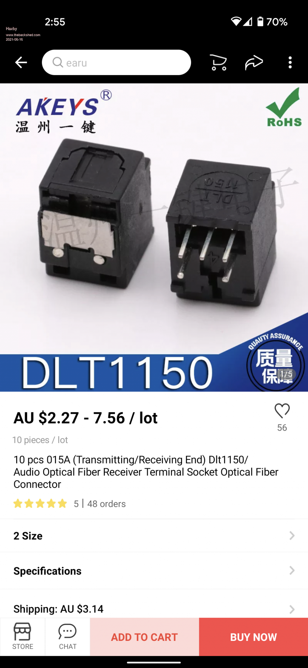 The different part numbers relate to the different mounting styles. Vertical horizontal or panel mount screw. There are also ones with window shutters or removable dust plugs. I found it hard too but once I found one type close to what I wanted, I searched within that store to find the other options. My bet is they all have the same optical chips in them. We will see what arrives. |
||||
| Haxby Guru Joined: 07/07/2008 Location: AustraliaPosts: 418 |
Also the pinouts for the TX were hard to find. After experimenting, this is what worked for me. Note these are the ones I bought from altronics to test, not the ones above which haven't arrived yet. 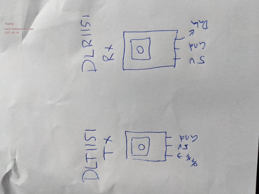 |
||||
| Haxby Guru Joined: 07/07/2008 Location: AustraliaPosts: 418 |
I received the DLT1150 and DLR1150 from AliExpress yesterday. The receivers do not function the same as the DLR1151 that I purchased from altronics. They seem to have a minimum frequency that they operate well on, but lower than 600Hz I get noise in the trailing square wave. I did a video here where I am altering the signal generator frequency built into my DSO. You can see noise on the signal when operating at lower frequencies, but not on higher frequencies. The altronics bought DLR1151 does not have this issue. Video: here Any thoughts? |
||||
| Warpspeed Guru Joined: 09/08/2007 Location: AustraliaPosts: 4406 |
Have you only tested one device, it may be faulty ? Cheers, �Tony. |
||||
| Haxby Guru Joined: 07/07/2008 Location: AustraliaPosts: 418 |
Ah I think you have nailed it. They might be VERY static sensitive. I tested 4 so far. 2 are behaving strangely, the other 2 are fine. When my PCBs come in I'll be sure to solder them on a static dissipative mat... |
||||
| Haxby Guru Joined: 07/07/2008 Location: AustraliaPosts: 418 |
I don't have a 30pf cap on hand. The data sheet says to put one between ground and data out. Maybe that's a clue? What is "loading effect"? I DO have a decoupling 0.1uf cap on the power pins  Edited 2021-07-03 15:56 by Haxby |
||||
| Haxby Guru Joined: 07/07/2008 Location: AustraliaPosts: 418 |
Ok I've been procrastinating a lot on this, as lockdown seems to drain my enthusiasm for everything but I thought it was time for an update. I've changed tack somewhat and will be using the 50A igbts recycled from aero-sharp inverters. It seems that the 1.5kw, 2kw and 3kw aerosharps all use the same igbt module. They have a small aero-sharp PCB that mates with the igbt module. This PCB has the optocouplers that drive the igbt h bridge module. 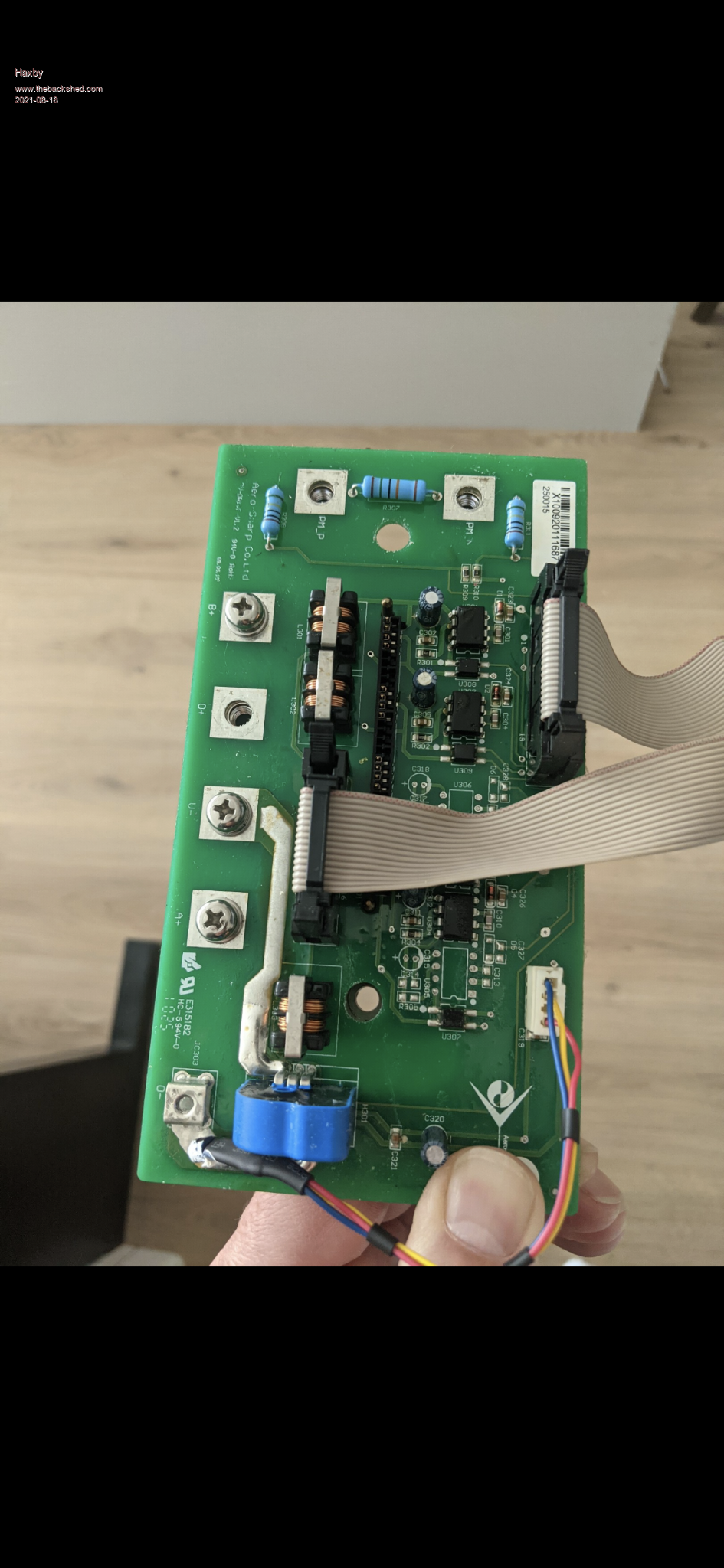 There are 2 ribbon cables that come off the boards. One cable supplies the isolated 15v power supplies (3 rails) and the other cable supplies the logic signals and DESAT out. So I designed a board that drives and controls 4 of these modules, which in turn is controlled by Poida's mega mini code. Communication between these will be those optical toslink cables discussed in previous posts. 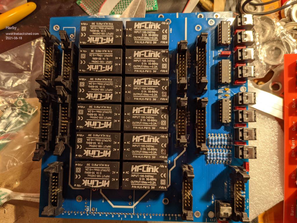 So for a 3 phase system, the tally will be 12 igbt modules with aero-sharp PCBs, connected to 3 of my blue boards.... Getting there, but as I say, I'm really struggling with motivation during lockdown! |
||||
| Warpspeed Guru Joined: 09/08/2007 Location: AustraliaPosts: 4406 |
Lockdown is certainly depressing, and its doing enormous damage to the community. Its not likely to end very soon either. Stick with it Phil, your project is coming along nicely. Cheers, �Tony. |
||||
| Haxby Guru Joined: 07/07/2008 Location: AustraliaPosts: 418 |
Just an update on the project. Long story short is that the DLT1150 and DLR1150 toslink spdif optical transmitters and receivers are not suitable for this project. While the data sheet states they work from DC, I have found in practice that these (probably clones) need some sort of minimum frequency. Now the two I bought from altronics do work well, but the 100 odd ones I bought from Ali express are hit and miss. The problem is that *Some* operate down to DC but others need a minimum frequency. I tested some more today and they needed 2khz as a minimum. So they might all work reliably at let's say 5khz to 1mhz. But any lower, and they have a bunch of garbage at the trailing edge of the square wave. Given that they would never be used at DC or very low frequency in the audio application that they are designed for, I can't really blame them for not working for me. My suspicion is that the auto-gain circuitry built in to the optical sensors is expecting some minimum frequency of 100 kHz, and when it doesn't receive a "low" for a while, it turns down the sensitivity of the optodiode to a level where it gets one, one way or another. Anyway now I'll have a think about either sourcing brand-name toslink parts, or moving to the more expensive but purpose built Tyco brand of digital optical TX and RX pairs. |
||||
