
|
|
Forum Index : Electronics : Bruce Inverter build
| Author | Message | ||||
| wiseguy Guru Joined: 21/06/2018 Location: AustraliaPosts: 990 |
Hi Aaron, its late and I havent had a chance to fully investigate. I interpret the instructions that as long as you are measuring between 8 - 300V you dont need a converter, if you wanted to measure between 0 & 8 volts (and higher) you need a separate 5 -12V supply as the unit cant work below 8V with the direct power supply. For instance if you want to measure down to 0.5V you need a separate supply to provide the meter with enough working voltage to operate and display with. As long as you are not interested in reading input voltage below 8V you should be good to go with the direct input only? Good luck - I want to hear how it goes, interesting looking meter ! If at first you dont succeed, I suggest you avoid sky diving.... Cheers Mike |
||||
| brucedownunder2 Guru Joined: 14/09/2005 Location: AustraliaPosts: 1548 |
Thank You Mike. All seems to be OK , I separated the 12 volt and 48 volt supply feeds.. I think the parallel negative feeds were the problem. Your analysis was correct, and once again we thank you for your knowledge shared. Bruce Bushboy |
||||
Revlac Guru Joined: 31/12/2016 Location: AustraliaPosts: 961 |
Ok, Thanks guys, looks like the problem is now solved.  Be nice to see that it is working, hope to see a photo soon.  Cheers Aaron Off The Grid |
||||
| Revlac Guru Joined: 31/12/2016 Location: AustraliaPosts: 961 |
Here is a photo Bruce sent, with the Meter working, Green looks nice and easy to read.  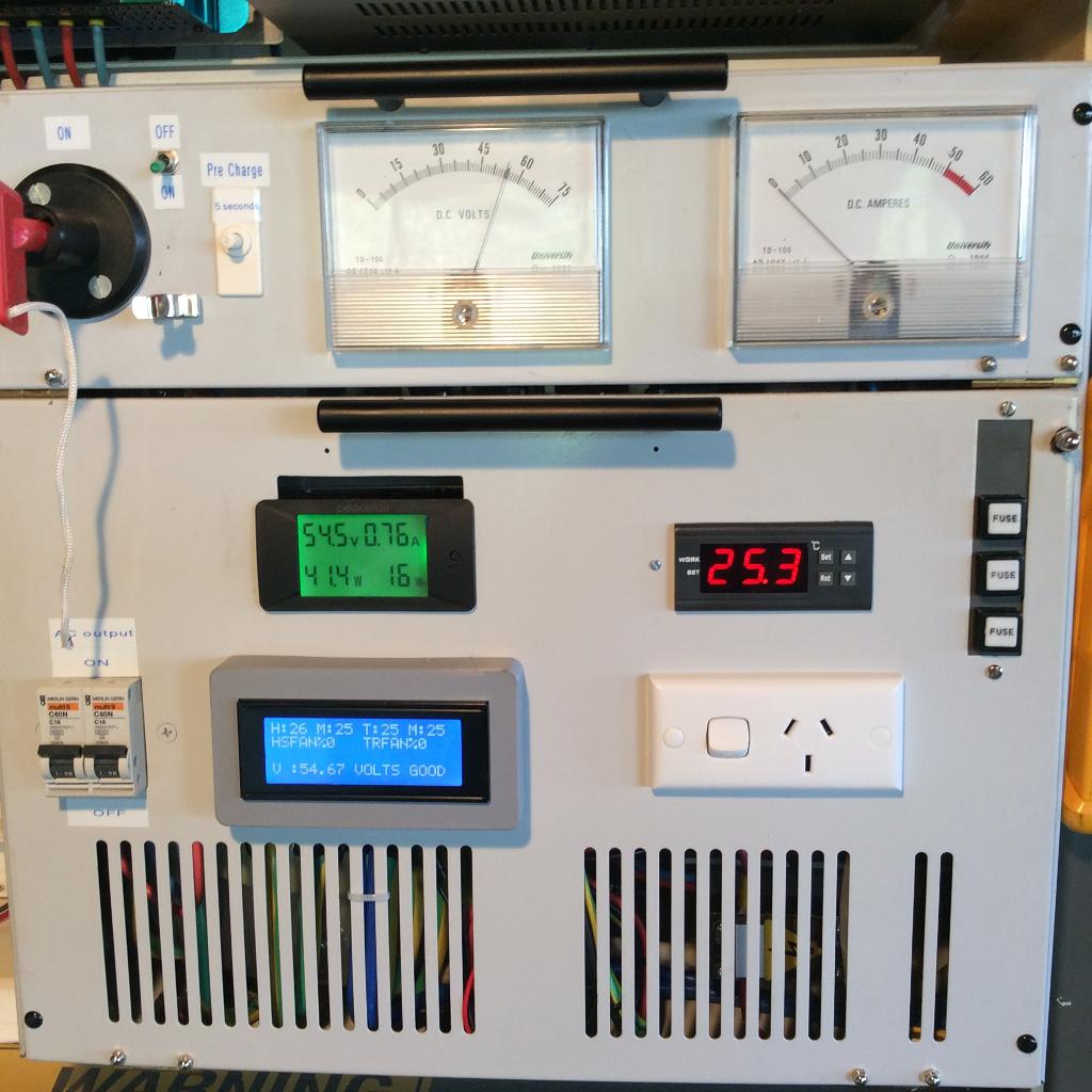 Cheers Aaron Off The Grid |
||||
| wiseguy Guru Joined: 21/06/2018 Location: AustraliaPosts: 990 |
Looking good Bruce & Aaron, well done! I had 3 of those rectifier units, were they STC ?? but they were 2 or 3 times taller and weighed a ton. Had the biggest C-cores I had ever come across and they were 48V. This was before I knew I wanted to generate 240V from 48V - I kept them for ~ 10 years and eventually threw them all to the dump ~ 2011 when I sold the business and had to vacate the premises quickly, still brings a tear to my eye.... but I guess it made the wife happy that they didn't relocate to our house. Do you want any of the analog meters - I still have a few from them ? - look identical to yours and they need a good home. I also still have a few sets of the sturdy L brackets for the bottom to stand the case up from the ground, you could have some of them too if you want them. If at first you dont succeed, I suggest you avoid sky diving.... Cheers Mike |
||||
| brucedownunder2 Guru Joined: 14/09/2005 Location: AustraliaPosts: 1548 |
Hi Wiseguy. Thanks for the offer,I use those analogue meters in a few of my projects. I used to have a cad programme that the draftsman where I worked set up for me to make my own meter faces. retired now and a lot of that stuff disappeared ,probably from my helpful family lot !!. My Inverter started off by gutting that Ericsson rectifier that I scrounged from our recovered equipment depot. I reused some of the gear in it and sanded and repainted the shell. I also hinged the front panels for convenience in servicing. Hang onto those meters,I'll remit you costs and you can post them to me at your conenience. Either I or someone else will use them one day. I'm a ham radio guy and frequent the hamfests couple times per year. It's amazing what electronics you find in their stalls. Mike, thanks for your help in interpreting the wiring instructions of that power meter, it is working . My mobile is 0427747748 for a chat ,in my workshop most days... Bruce Pickers Bushboy |
||||
| Revlac Guru Joined: 31/12/2016 Location: AustraliaPosts: 961 |
@Mike, The ones I have, 2 of them are Power Electronics 50Amp 90Kg (still use them) 3 other's are Ericsson 50Amp they are just a smaller and more compact version of the PE. Also have 2 20Amp units as backups. They have massive chokes in them as well. I used one Ericsson 50Amp to build My inverter, very easy to wind the large C cores, I would have preferred to have a pare of them (core type construction) and wind up one big coil, but the C cores make A good inverter.  Some links to the early days. Another Inverter Build EI Transformer various types They were fun to build. Edited 2022-04-08 19:17 by Revlac Cheers Aaron Off The Grid |
||||
| wiseguy Guru Joined: 21/06/2018 Location: AustraliaPosts: 990 |
Hi Aaron, thanks for the links and pictures. The C-cores I had looked like the day they came out of the factory despite their age. They were obviously kept in a clean room environment, I believe the units were originally from the TAB betting agency in Adelaide. I have been following Rogerdw's build of his monster toroidal, I think that I will have to build a similar one of those too, the ultimate, should not outgrow that in a hurry, but I will be using it with sine pwm not a warpverter. I will call Bruce next week sometime. If at first you dont succeed, I suggest you avoid sky diving.... Cheers Mike |
||||
| brucedownunder2 Guru Joined: 14/09/2005 Location: AustraliaPosts: 1548 |
Good Morning all , mainly posting to confirm my new password works,,,, All looks OK .. I've got a couple of solar controllers, called "Intelligent Solar Charge Controller" . They have been good for my small 48 volt system ,have had them 10 ,something years , but one has shown to be a bit erratic on my current meter needle ,lately. It gets up to the float voltage ,then the meter needle starts quivering back and forth about 1 mm or so ,,, rather than return to the float sequence... I have an identical mate ,it behaves perfectly. So, I've been switching over to it ,til I get this crook one sorted. I switch on extra load for a short time ,til the battery drops voltage a bit , and then it resumes bulk charging . til it gets voltage up to float and then repeats this quivering sequence.??? Any clues, I've checked all wiring and tried adjustment of the high volts ,but that does not seem to fix the fault. Thanks, Bruce Bushboy |
||||
| phil99 Guru Joined: 11/02/2018 Location: AustraliaPosts: 1768 |
" I've checked all wiring and tried adjustment of the high volts ,but that does not seem to fix the fault." It might be the float voltage setting causing the problem. I appears to have lost the differential between bulk and float. As soon as the voltage starts to drop after bulk charge it is switching back to bulk charge in a rapid loop. Are the various setpoints adjusted in software or via trim-pots? If the latter give them a squirt with contact cleaner and wind them back and forth a few times to clean the tracks then readjust to correct settings. Check for faulty solder joints around the trim-pots and related components. |
||||
| brucedownunder2 Guru Joined: 14/09/2005 Location: AustraliaPosts: 1548 |
Hi Phill99 I've been inside , but no trim pots or mechanical parts , just three buttons that change the settings , which all work . mostly surface mount devices , the only components I could measure ,against the working unit , would be the six Mosfets for. possible degradation ???. I'm trying to post a pic , so wish me luck !!. Thanks for your interest. Bruce Bushboy |
||||
| brucedownunder2 Guru Joined: 14/09/2005 Location: AustraliaPosts: 1548 |
OK, back to the pic. of the PWM 50 Amp controller . there are two similar controllers in the pic , it's the larger of the two (right hand side). I opened it , no serviceable parts ,except for the six Mosfets on the rear of the heatsink. I wondering if one of those is faulty and not allowing the bulk to float charging operation ??? Thanks , Bruce 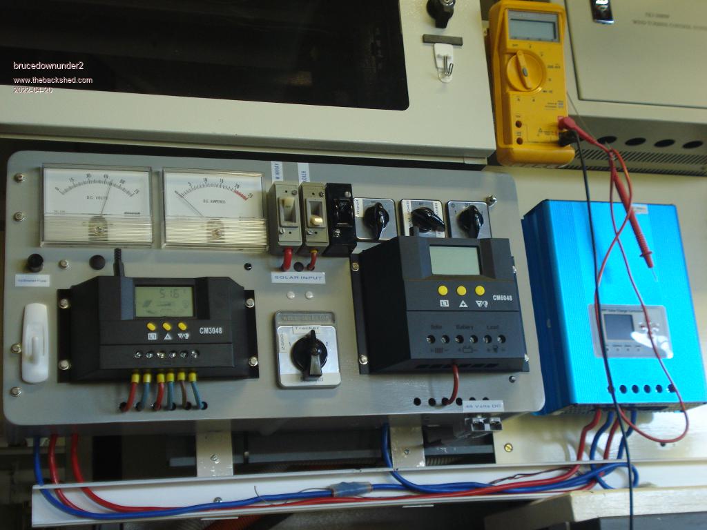 Bushboy |
||||
| Murphy's friend Guru Joined: 04/10/2019 Location: AustraliaPosts: 580 |
Bruce, in my experience of more than 100 mosfet failures, they all fail short circuit. Its unlikely that one in a parallel connection survives the other going short. |
||||
