Notice. New forum software under development. It's going to miss a few functions and look a bit ugly for a while, but I'm working on it full time now as the old forum was too unstable. Couple days, all good. If you notice any issues, please contact me.
Forum Index : Electronics : Would you like to see my collection.................of inverters?
Page 1 of 2
Author
Message
Murphy's friend Guru Joined: 04/10/2019 Location: AustraliaPosts: 583
Posted: 09:14am 20 May 2021
Copy link to clipboard
Print this post
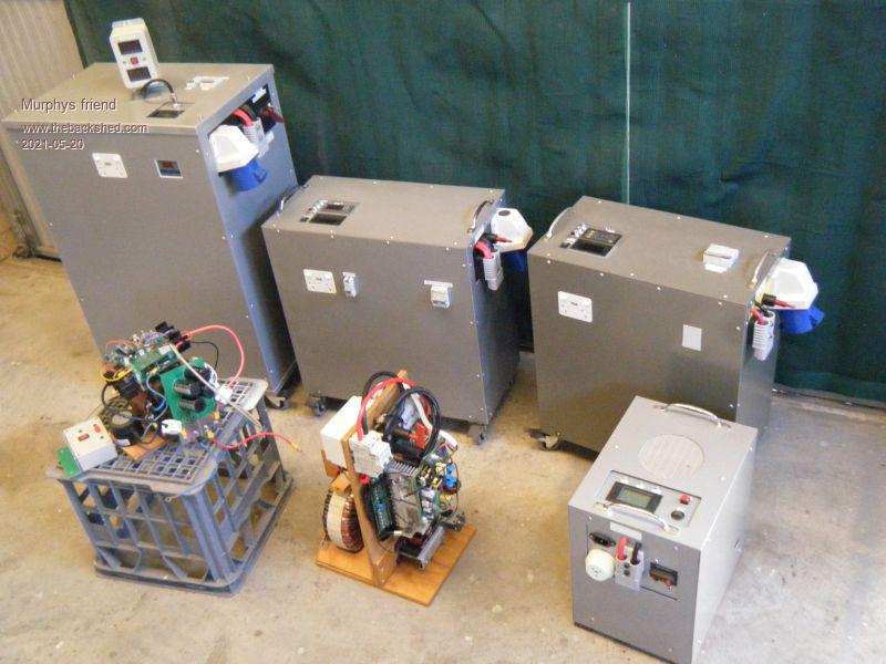
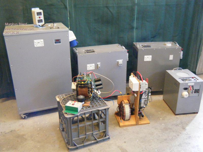
I finally got that troublesome warpinverter going again so I thought I line up all my inverters for a picture
In the back row on the left is the warpverter, a bit of a heavyweight at over 150kg. The top & bottom covers are a recycled aerosharp box lid which gives you an indication of its size.
Next to it is my 6KW nano inverter with the opto isolated driver, as seen in a recent post here. That one weighs around 75kg with its double stack core and 90mm sq primary winding.
Then my 3KW inverter, same drive as the 6KW. Still too heavy to lift, its also on castors .
Last in the back row is my 1.5KW inverter which also has drivers like the two bigger ones. There was a post about this one a while ago. I can manage to carry this one .
In the foreground, on the milk crate, is a small 4 mosfet test inverter I built when Poida first came out with the nano. I made that to experiment with that idea.
Last, on the plywood frame, is the inverter that started all this craze. It is the 8KW (Chinese KW) Powerjack inverter module that oztules et al used to make home built inverters that perform better than the factory versions. I had used that inverter for some time, with a bigger toroid, when it was shoe horned into an Aerosharp box. But the constant fan noise eventually started me building my own inverters from scratch into suitable bigger enclosures. I might make a suitable enclosure for it so it can be used plug in like all the others.
Having all inverters plug in makes change over time less than a minute, not that I anticipate any more blow ups , had my fair share of those.
If anybody likes to see more details, I do have more pictures .
Now I think I'm done with inverter building. After all, I have a spare for the spare now. Only two inverters are used at a time, a big one for the power and a small one for the lights of my house. Its off grid now but has the connection to it maintained.
So, there are a few freebies to be had which should get a newcomer well on the way to build an inverter. See picture below. Local pickup, Perth WA only.
Warpspeed Guru Joined: 09/08/2007 Location: AustraliaPosts: 4406
Posted: 10:28am 20 May 2021
Copy link to clipboard
Print this post
Wow Klaus, that is a whole extended family of inverters, quite an achievement.
You certainly will never be caught short if the grid ever goes down.Cheers, �Tony.
nickskethisniks Guru Joined: 17/10/2017 Location: BelgiumPosts: 411
Posted: 12:43pm 20 May 2021
Copy link to clipboard
Print this post
That's an amazing collection you have built!
I like your eye for quality and detail, nice it's all pluggable, makes things easy when something went wrong or you want to do service on the units.
Haxby Guru Joined: 07/07/2008 Location: AustraliaPosts: 418
Posted: 08:58pm 20 May 2021
Copy link to clipboard
Print this post
Nice collection of inverters! This will be me in a few years time as the collection grows.
Did you work out why the warpinverter was blowing up? Edited 2021-05-21 07:00 by Haxby
Murphy's friend Guru Joined: 04/10/2019 Location: AustraliaPosts: 583
Posted: 08:04am 21 May 2021
Copy link to clipboard
Print this post
Thanks, its an interesting hobby which had become a little too addictive to me .
Re your question, no, no definite answer. I did a complete re build of the electronics (only Tony's control board is the same)and this fixed it so far. If you are interested how that build looks like now let me know.
Here are some statistics of the inverters shown above.
No load (idle) power:
Warpverter 27W @ 54 VDC
6 KW nano/opto drive inverter 29W @ 55 VDC
3 KW -"- 17W @ 55 VDC
1.5 KW -"- 11W @ 55 VDC
Powerjack 8KW, optimised choke 27W @ 55 VDC
Now something that really surprised me. Having two similar power rated inverters of a very different design, it occurred to me to do a voltage drop vs. power and efficiency comparison.
Keep in mind that I do not have lab rated instruments but I did use the same power meter, the same load (2 kettles & 1 immersion heater)and all was powered from the same battery bank.
The different power levels with the same load are perhaps a result of the cold water in the kettles when I started testing with the nano inverter and the water having heated up some by the time I tested the warpverter.
What surprised me was the very good voltage regulation of the nano inverter (well done Poida ) compared to the not so good regulation of the warpverter.
Now, Tony has come up with a clever cure for this, using current feed back from a hall sensor. I tried that back when my original warpverter still ran and that mod works well. But it involves removing a a resistor from the control board and connecting wires there, something the tiny PCB pads make not easy for old eyes. I have a suspicion that tinkering with that upset something elsewhere as that inverter soon after started its blow mosfets season. If I ever get bored I'm inclined to re do Tony's control board on a 100x100PCB with that mod included.
The efficiency of the nano inverter was also a fair bit better at low power, perhaps something to do with one transformer versus 4 transformers.
Before that testing started I watched my grid tie back charging put 50Amps into the battery bank and the warpverter is definitely quieter at this task. Hardly a hum to be heard. But the AC voltage goes up past 240V when that happens so that's why its set at 235v at no load. The nano inverter also increases the AC voltage while back charging but with a smaller margin.
Warpspeed Guru Joined: 09/08/2007 Location: AustraliaPosts: 4406
Posted: 10:14am 21 May 2021
Copy link to clipboard
Print this post
Very glad to hear your Warpverter is finally behaving itself. Still feel that the problem was probably those plugs and sockets in the gate and gate driver circuitry.
One other test you might like to try is the transient load test. Its a bit subjective, but might be interesting none the less.
Connect up an incandescent light bulb to the inverter output, then switch on something that has a very high but brief starting up inrush surge, like typically a refrigerator.
Light flicker can be quite annoying, at least I find it so.Cheers, �Tony.
Haxby Guru Joined: 07/07/2008 Location: AustraliaPosts: 418
Posted: 12:45pm 21 May 2021
Copy link to clipboard
Print this post
Klaus, did you end up being able to capture the gate drive signals on a DSO?
Murphy's friend Guru Joined: 04/10/2019 Location: AustraliaPosts: 583
Posted: 02:21pm 21 May 2021
Copy link to clipboard
Print this post
No, my scope skills (and equipment) are not quite up to that level. Its all closed up now anyway.
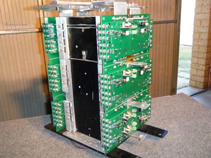
I use a totem pole final after the FOD 3182 opto driver, I feel that the fast 8A rated transistors are more suitable to drive paralleled mosfets. They certainly stood up to a 6KW load. The 40 mosfets are in a 16, 12, 8, 4 per full bridge arrangement.
Murphy's friend Guru Joined: 04/10/2019 Location: AustraliaPosts: 583
Posted: 02:45pm 21 May 2021
Copy link to clipboard
Print this post
Tony, you are probably right about those connectors, I replaced them with nuts & bolts .
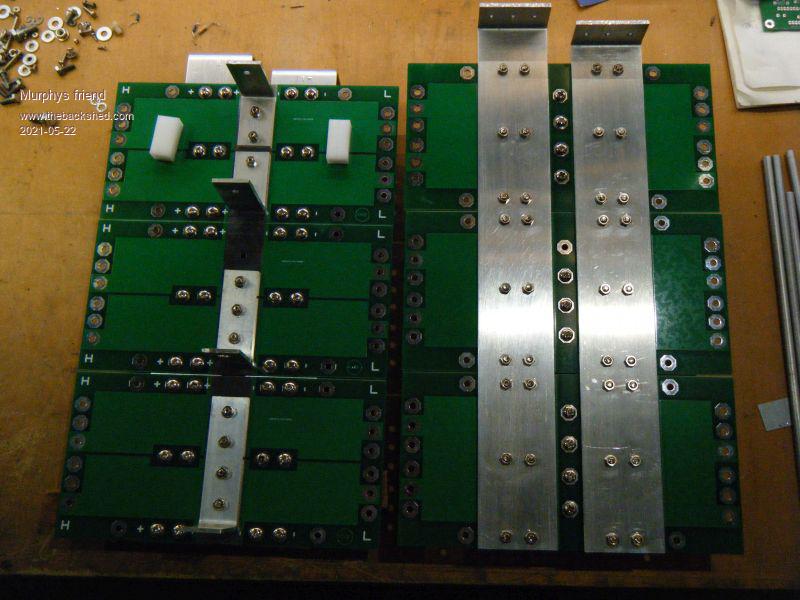
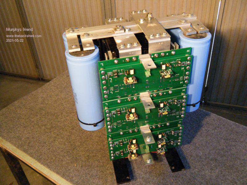
A few pictures, first the power PCB half bridges, each side shown.
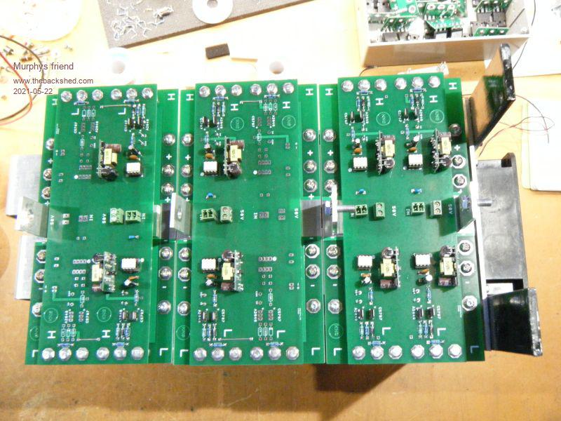
Then with the driver boards added.
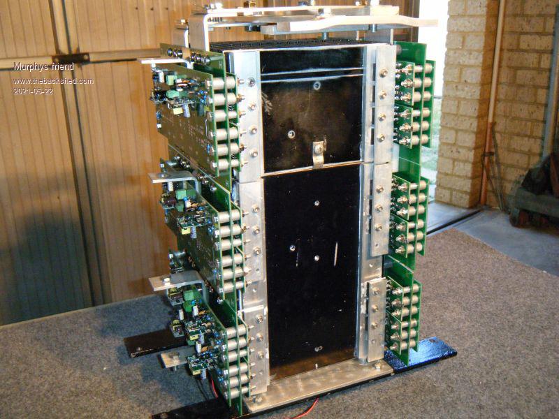
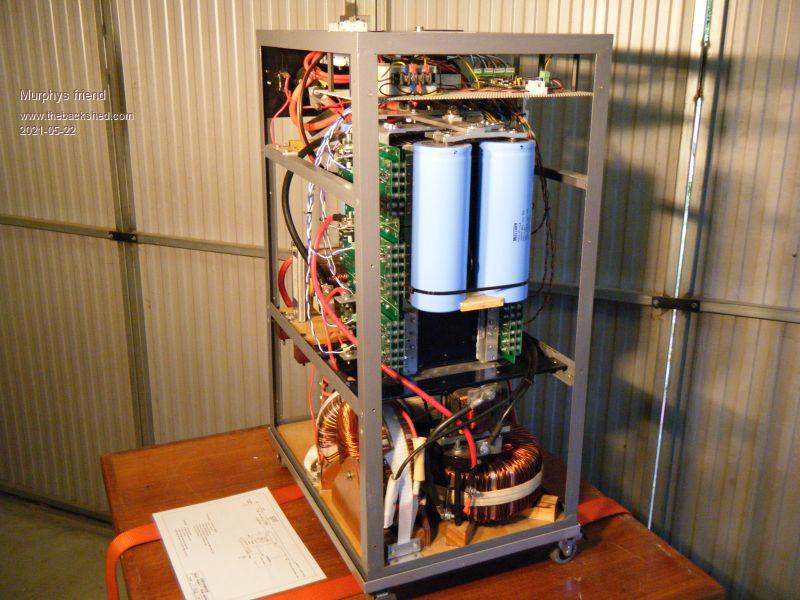
Now the rest of the guts.
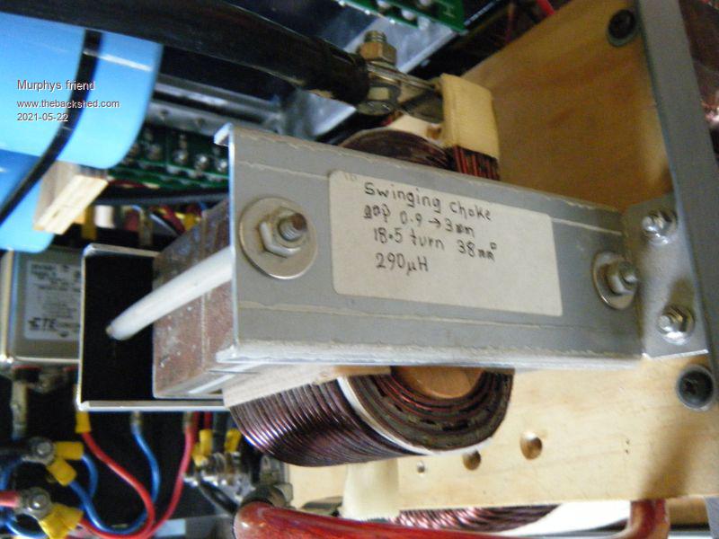
A picture of the swinging choke at the big transformer. There is another choke at the second transformer.
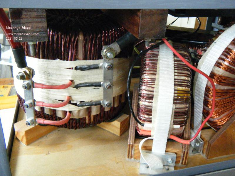
And last a pic of the big transformer
Warpspeed Guru Joined: 09/08/2007 Location: AustraliaPosts: 4406
Posted: 09:39pm 21 May 2021
Copy link to clipboard
Print this post
Those nuts and bolts certainly remove any doubt as to any intermittent gate connections !
A great effort, its very difficult to design a neat practical layout running so many mosfets in parallel.Cheers, �Tony.
Murphy's friend Guru Joined: 04/10/2019 Location: AustraliaPosts: 583
Posted: 06:45am 22 May 2021
Copy link to clipboard
Print this post
Thanks Tony. I tried your incandescent lamp test today and yes there is a marked dip in the brightness of the 60W bulb when I fire up the 14" 2.2KW abrasive cutoff machine. The CRO AC trace also takes a bad hit for an instant.
Might have to include that clever hall sensor mod again in the future but for now the inverter is powering my house to see how it goes as time progresses.
Warpspeed Guru Joined: 09/08/2007 Location: AustraliaPosts: 4406
Posted: 08:01am 22 May 2021
Copy link to clipboard
Print this post
I have been thinking about incorporating that Hall sensor modification in my own Warpverter. Must pull my finger out and lay out another slightly larger control board and do it properly.Cheers, �Tony.
Murphy's friend Guru Joined: 04/10/2019 Location: AustraliaPosts: 583
Posted: 09:06am 22 May 2021
Copy link to clipboard
Print this post
Guess what I started doing once the rain arrived here - lay out a warp control board . Perhaps we could have a competition?
I saw 1W DC/DC converters at LCSC, they have + - 5V out for 12V input and are SIL package. At the moment at half price there (IA1205S-1W). These would save your charge pump IC & ass. parts area. 12V is used for the fan in my inverter, sourced from a 75V input DC/DC. Do you think 1W is sufficient for the + - 5V supply?
Warpspeed Guru Joined: 09/08/2007 Location: AustraliaPosts: 4406
Posted: 09:28am 22 May 2021
Copy link to clipboard
Print this post
Its three years ago since I did the control board, but as I remember, the total current of the +5v supply was about 110mA. Most of that was current to drive the sixteen opto isolators. Roughly half will be on and half off at any instant in time, at around 10mA each. The only other significant loads are the oscillator module, and shunt voltage regulator for the 2.5v reference. All the CMOS chips draw almost nothing.
The -5v supply is only a few microamps, also virtually nothing.
What I might do is make the board about 20mm to 25mm longer at the input end to accommodate the Hall sensor, but leave the four 3mm mounting holes in the exact same places.
Dont forget to place a 100nF bypass capacitor directly across every chip.Cheers, �Tony.
BenandAmber Guru Joined: 16/02/2019 Location: United StatesPosts: 961
Posted: 03:56am 01 Jun 2021
Copy link to clipboard
Print this post
Wow awesome stuffbe warned i am good parrot but Dumber than a box of rocks
BenandAmber Guru Joined: 16/02/2019 Location: United StatesPosts: 961
Posted: 05:17am 02 Jun 2021
Copy link to clipboard
Print this post
I see what you guys build on here as a piece of art
I remember seeing at least one of your inverters before
I am still impressed
The newbie that ends up with one or parts will be very lucky
I am almost never able to add anything of value on this forum
So I try to add a nice word when it is so clearly deserved I I enjoy seeing the pics while reading the thoughts of the artist while they are working on there master piece
I remember reading a post worpspeed wrote about the benefits of voltage feed foward instead of back feed
The last time I asked warp about it I think he said some one had tried it
Is there any chance you may consider DC voltage feed forward?
Have a blessed day every one! Edited 2021-06-02 15:43 by BenandAmberbe warned i am good parrot but Dumber than a box of rocks
rogerdw Guru Joined: 22/10/2019 Location: AustraliaPosts: 795
Posted: 09:57am 08 Jan 2024
Copy link to clipboard
Print this post
Hi Kaus, sorry to revive an old thread but I was trying to work out what you did with the chokes in your Warpverter ...
What problem were you solving by fitting them ... and exactly where in the circuit were they. I noticed Alston used one as well but I never understood why it was needed.
I came across this while looking for details on the additional current feedback system that you trialled at some stage ... which I haven't found yet. Thanks.Cheers, Roger
Murphy's friend Guru Joined: 04/10/2019 Location: AustraliaPosts: 583
Posted: 07:56am 09 Jan 2024
Copy link to clipboard
Print this post
Hi Roger, you do like trolling through my old threads .
That choke was in the primary of the big transformer. This has a tremendous kick with the 50Hz square wave. Perhaps it's because I use a 48V battery bank, warpspeed says that with his 100V battery bank he does not see a need for a choke. Anyway after feeding handfuls of HY4008's to this monster I decided a choke may help.
Building this warpinverter was an interesting, enjoyable but (compared to my other inverters) expensive task. Running it has been one frustration after another, so much so that its now in pieces again and I'm seriously thinking of using the big transformer to make an EG8010 or nano based inverter. Not that I need another one - it's just that I like building them.
Anyway, you may want to know why I lost faith in my warpinverter. By now I had re- build my other inverters several times, hopefully improving them along the way. They are now very reliable, doing what I ask of them, silently.
The warpinverter had a habit of playing up when I tried to re start it after it's been idle for some time. The reason it was idle in the first place is that it is noisy. It can growl dreadfully when it's backcharging. My other inverters are now silent at this task, thanks to KeepIS idea of fittimg sendust core chokes to the primary.
Regarding that current feedback you mentioned, it was included as my warpinverter has a poorer AC voltage regulation (at 48V DC) than the EG8010 inverters. The Hall sensor feedback warp suggested works (its fiddly to adjust) but only one way. So, when its set for drawing power from the battery its good but when back charging the AC voltage gets way too high for my liking.
Have fun with your warpinverter, with hindsight I would not build one now.
rogerdw Guru Joined: 22/10/2019 Location: AustraliaPosts: 795
Posted: 12:53pm 09 Jan 2024
Copy link to clipboard
Print this post
Thanks for the info Klaus. There's such a lot of info on this site ... it's just a matter of finding it ... but nice to know you're still prepared to answer some questions.
When you say the primary has a tremendous kick with the 50Hz square wave ... do you mean a lot of physical noise ... or are you talking about electrical distortion etc ... or random blow-ups?
And I'm sorry to hear you're having second thoughts, that's not what I wanted to hear. Reading between the lines I suspected you weren't using it at the moment, so thanks for filling me in.Cheers, Roger


 .
. .
. , had my fair share of those.
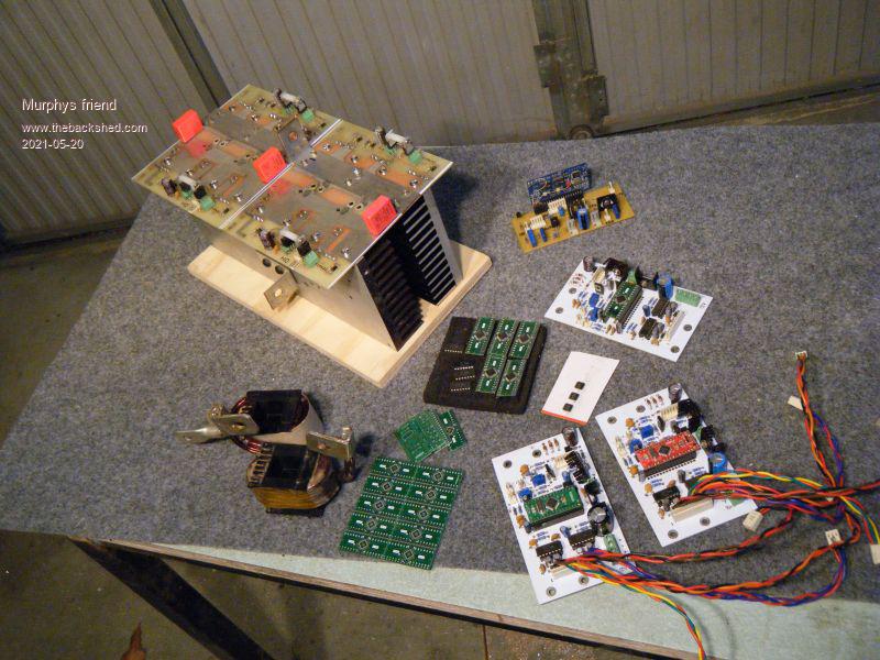

 as the collection grows.
 ) compared to the not so good regulation of the warpverter.