
|
|
Forum Index : Electronics : I wasn't even hunting - but look what I bagged!
| Author | Message | ||||
| rogerdw Guru Joined: 22/10/2019 Location: AustraliaPosts: 792 |
No trouble. Now that I've had time to think about it, I'm sure one of these will be plenty big enough without stacking another ... the only question was whether the hole size is big enough to allow the required number of turns. My main reason for posting was to let others know that we can put these early SMA (and BP Solar) inverters on our watch lists as well as the Aerosharps. The model number for mine was SMC6000A ... and there are also SMC4500A and SMC5000A ... and even though it had a BP Solar cover ... still used the SMA model number. I have got the impression from looking around that their early ones with toroids had model numbers starting with SB----- ... and I do know that their later ones without toroids have 'TL' in the model number, designating that they are 'transformerless'. Haha, thanks. I think I was as apprehensive as anyone here about winding one before I started ... but now that I have had a go, I actually enjoyed the challenge. For any I wind in the future, I will do my homework first ... know how many turns I need ... and from the wire size determine how many turns will fit per layer etc And not necessarily wind with adjacent wires touching each other ... leave a gap so that the full winding will be a complete number of layers ... eg. not two and one third layers but three full layers. The advantage of that is if you wind your first layer carefully ... the following layers fall into place into the gaps from the previous layer. Keeps it nice and tidy. Then for me, doing a print to sit on top of the core, with the wire positions shown ... and then another to go around the outside ... to help keep the wire spaced just right. You could even create that by hand with a protractor and ruler if necessary. I never tried the method using small spools of wire or with the wire wrapped on a longer length of timber, I used a large hoop which allowed the full winding to be put on without fear of having to join it. Anyway, you live in Adelaide don't you? If that's correct, I'm only an hour out ... so I'm sure we could get together and I could give you a hand to get it started. It's the sort of thing that when you see how it goes, you'll be able to say get out the way and let me do it .. it's a piece of cake.  Cheers, Roger |
||||
| Warpspeed Guru Joined: 09/08/2007 Location: AustraliaPosts: 4406 |
It will always be big enough. If the original design was correct, the cross sectional area of copper in the primary and the secondary should end up being very nearly the same, regardless of the transformer ratio. For example, if you plan to rewind a primary for half the original voltage, it will require half the turns. But it must also carry twice the current, so the wire cross section must double. Half the turns x twice the wire cross section = the same copper volume. The original transformer was almost certainly wound on an automatic coil winding machine. The larger the core, the larger the machine required, and the more space required for the machine to operate within the hole. The space required for the machine sets a limit of how much of the hole can actually be filled with copper. So there must always be a significant wastage of space. With a hand wound toroid, the hole can be filled to a point where the last turn can be squeezed in, leaving zero space for even one more extra turn. So if you start with a machine wound toroid, and rewind the top winding by hand, there will always be sufficient physical space, unless the wire used is a lot thicker than it really needs to be. Cheers, �Tony. |
||||
| Davo99 Guru Joined: 03/06/2019 Location: AustraliaPosts: 1577 |
Dilettante Question here... What are these Torroids made of and could they be replaced by steel? Seems there is such a demand for them I'm wondering if they couldn't be made from layers of steel like found in a transformer? Be easy and not that exy to have the Rings laser cut out of 1/4 or 1/2" Plate and built to any specs required by stacking them together. If they have to be non conductive, couldn't they be made from Resin? If they are semi conductive, could not some metal powder be mixed in the resin? |
||||
| Warpspeed Guru Joined: 09/08/2007 Location: AustraliaPosts: 4406 |
Solid steel and cast iron only work for dc electromagnets. Whenever there is ac, very thin laminations must be used that are insulated from each other. The thinner the better, but about fifteen thou might be a maximum at 50Hz for stamped laminations. Yes indeed, iron powder and resin is definitely used for some higher frequency applications, and ferrite, a sort of metallic ceramic is even better at even higher frequencies still. Our precious toroids are very special, made from a steel alloy with a lot of silicon in it and formed into a very thin continuous ribbon. This is wound onto a steel mandrel, and then heat treated. The steel ribbon has an insulating surface, probably some kind of oxide? So the finished toroid looks like a solid piece of steel, but its actually a very large number of turns of very thin steel foil all bonded together into a solid lump. Not the slightest possibility of making something yourself that is going to work. Cheers, �Tony. |
||||
| Davo99 Guru Joined: 03/06/2019 Location: AustraliaPosts: 1577 |
Thanks Tony. very interesting. What is the torroids Purpose? To conduct electromagnetic fields, to suppress, magnify them? Are the cores of these Chokes in GTI's a suitable torroid material or are they just Ferrite? Thanks for the information. |
||||
| Warpspeed Guru Joined: 09/08/2007 Location: AustraliaPosts: 4406 |
The purpose of the core is to provide the easiest possible path for the magnetic field that links both primary and secondary together magnetically. Chokes in most (but not all) grid tie inverters are made of the same material as the toroid. The toroid "foil" is wound on a round mandrel to create the toroidal shape. The choke is more commonly wound on a rectangular mandrel, then cut in half to make two "U" cores. These U cores can then be inserted into a winding to make a choke. Chokes always have some, or a lot of dc current flowing, and so usually require an air gap in the magnetic path. The two U core construction allows a small slice of non magnetic material sandwiched in between the two U core halves to form this air gap. Some inverter (and grid tie) chokes use powdered iron, or ferrite cores with an air gap. Cheers, �Tony. |
||||
| rogerdw Guru Joined: 22/10/2019 Location: AustraliaPosts: 792 |
Dave, here's how the experts make the cores. And Mike, here's my puny elcheapo version of one of the winding machines and the printed wire guide. 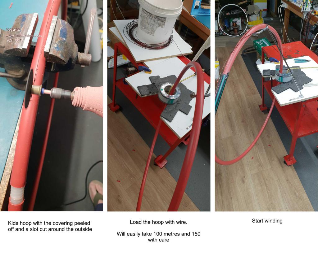 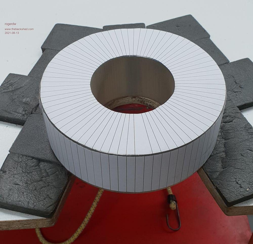 Cheers, Roger |
||||
| Murphy's friend Guru Joined: 04/10/2019 Location: AustraliaPosts: 580 |
Very true but one can get into hole space trouble by using plastic coated 'cable' for the primary. This insulation can use up as much space as the copper conductor within. I did get into hole space trouble with one warpinverter toroid (the first I wound) when re using too much of the mylar tape insulation between the secondary layers. It ended up a hacksaw and start over job. Using cable laid enameled wire for my higher current primaries were a big space saver. And a great way to use up left over re cycled enameled wire. I did wind two primaries of my single core inverters with rectangular enameled wire which was rather hard to do by hand, the twisted cable laid wire was much easier. Just 7 twisted wires and using 3 of those in parallel for the big current primary of the large warpverter toroid. |
||||
| wiseguy Guru Joined: 21/06/2018 Location: AustraliaPosts: 990 |
Roger, thanks for the offer to see your method of winding a toroid, I would like to take you up on that. I reckon if I bring an empty toroid you could demo the first few layers for me  I did some research and know where you are located. Have you been there for eons or did you move there recently ? If longer term did you ever have anything to do with the raceway there? I spent my early school years growing up on a dairy farm at Clayton. It appears that automation has totally changed the way cows are milked today. - You do some pretty interesting repairs. If at first you dont succeed, I suggest you avoid sky diving.... Cheers Mike |
||||
| rogerdw Guru Joined: 22/10/2019 Location: AustraliaPosts: 792 |
You're welcome, and I'm very happy to do that if you'd like ... though with a bigger toroid a few layers may take a few hours. I've been in the town for forty years and in this location about six. I never really had much do do with the raceway other than the occasional visit though I did once race there when they held a short circuit event for motorcycles. It's a small world, an aircon friend who works here in town lives over at Clayton and you're right, dairy farming has certainly changed a lot over the years. I kinda got dragged into the field of work but it has paid off and I still find it fascinating and challenging at the same time. PM me when you're ready and we can organise a time to get together or just ring anytime. Cheers, Roger |
||||
