
|
|
Forum Index : Electronics : Mains OR switch
| Author | Message | ||||
| CaptainBoing Guru Joined: 07/09/2016 Location: United KingdomPosts: 1985 |
Morning forum. I have a refurb of a bathroom coming up. Currently there is an extractor fan (about 10W) that is slaved to the light circuit. What this means is that in order to have the fan on, you have to have the light on and during the day I really hate having to do that just to vent the steam from the shower. I have been tossing the idea around in my head for a "Mains OR gate" - a circuit that will take mains from either the lighting or the shower circuit to power the extractor fan. Logically this is what I am thinking of: 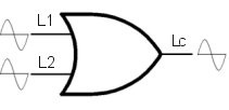 L1 and L2 are the shower and lighting circuits, Lc is the common mains output to drive the extractor fan. Neither input mains must back-feed to the other circuit - I don't want the lights coming on with the shower or worse trying to power the shower from a 6A lighting circuit. Using a mains relay/contactor it is very straightforward: 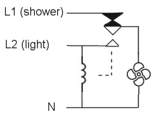 but... I want to avoid things that go clunk if possible. It has my brain tied in knots a bit and just when I think I have it I realise there is some problem which breaks the rules. I am convinced there is a triac matrix in there somewhere but I can't quite grab it. Anyone here got some ideas? All input gratefully received, even straight abuse  but please don't go down the "regs" route, I know all about that stuff, this is a mental exercise. but please don't go down the "regs" route, I know all about that stuff, this is a mental exercise. |
||||
| Solar Mike Guru Joined: 08/02/2015 Location: New ZealandPosts: 1122 |
I think "Clunk" is simplest, use 2 diodes connected to L1 and L2 to power your fan relay coil; the fan motor itself connected to another fused circuit L3 via the relay contacts. In our bathroom the fan always comes on with the light, as it also prevents the lamp from over heating (was halogen, now led) Cheers Mike |
||||
Revlac Guru Joined: 31/12/2016 Location: AustraliaPosts: 961 |
A triac is quite common in ordinary fans for switching speed and rotation on/off. Another thought, there was some sensor light's and some others that had, 2 working modes, turn on for first mode, turn off the immediately back on for the other mode, haven't opened up such a device to see how that works.....but that option would be useful for the fan light combination. Cheers Aaron Off The Grid |
||||
| CaptainBoing Guru Joined: 07/09/2016 Location: United KingdomPosts: 1985 |
Cheers @Mike & @Aaron for the ideas. @Mike, the problem is i don't have a L3 available, the fan needs to draw power from whichever Live is, err, live @Aaron your comment pushed me to think more about the triac thing. What is wrong with this picture? (could probably dispense with the two diacs but just in case there is some hum, don't want false triggering.) 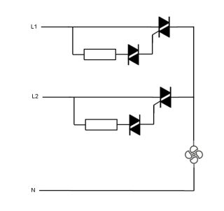 L1 and L2 are in-phase so if both are live, it should be OK. My concern would be with local voltage drop - the shower circuit is 7KW. |
||||
| InPhase Senior Member Joined: 15/12/2020 Location: United StatesPosts: 178 |
Why not just put in another switch? |
||||
| CaptainBoing Guru Joined: 07/09/2016 Location: United KingdomPosts: 1985 |
I want it automatic. Currently the fan comes on with the lights, but if I am showering during daytime, the lights aren't on... and neither is the extractor. |
||||
| mab1 Senior Member Joined: 10/02/2015 Location: United KingdomPosts: 149 |
If you don't need the fan when the shower isn't used then wire to the shower cct via a 3a fuse is the simple option. Option 2 Fit a fan with a humidistat to a permanent supply. Option 3 Fit an LED lamp - if you're running an electric shower, then the energy wasted by an led bulb won't make much difference. Option 4 Go down the clunky relay route. There might be a solid state relay route which would eliminate the clunks but i don't know if any ssrs can be controlled directly from 230v ac, but could be done indirectly via isolating dc psu's. |
||||
| CaptainBoing Guru Joined: 07/09/2016 Location: United KingdomPosts: 1985 |
All valid options - wish I was building from scratch but I have to work with what I have. The fan has its own pull-switch but it's always in the on position. At the moment, the fan is on when lights are. I intend to modify that so that IF (lights=on OR shower=on) THEN fan=on. I wasn't aware of the "humistat" fitted fans... quite like that but it still need a third supply which I don't have. The actual power use of the lighting isn't really an issue. I just want to run the fan on either circuit depending on selection. Clunky relay route is easy and I have the right relay with a DIN mount and some DIN rail I can screw to the rafter above the ceiling. It needs to be a SPDT (changeover) - haven't seen such a beast in SSR, but haven't really looked very hard. Adding more circuitry is not ideal (part of me want a micromite in there Ā  ) )I am going to hook up a couple of 800V triacs this weekend and play. I don't have any diacs atm so I will see if hum is a problem too - can't imagine it would be, the gate drive is reasonably low impedance (6.8K) I don't think the potential voltage drop locally when the shower is on will be a problem if the lights are on too as all it would do is supplement the shower circuit to the tune of a few volts... not really anything to be concerned about. we shall see! Edited 2022-04-22 00:19 by CaptainBoing |
||||
TassyJim Guru Joined: 07/08/2011 Location: AustraliaPosts: 5878 |
I am aware that the UK domestic wiring is very different than the Aus systems so have to be careful. Are the fan and light supplied form the same circuit/fuse? do you want two switches, one for light (and fan) and a second for just fan? are double pole switches available in your desired style/finish? If so, easy to implement. In Aus, we have 'fantastic' brand heat lamps with extractors. They do it all for you, and are nice on a cold morning. Jim VK7JH MMedit ┬Ā MMBasic Help |
||||
| CaptainBoing Guru Joined: 07/09/2016 Location: United KingdomPosts: 1985 |
Hello Jim, thanks for the interest. It's all getting a bit foggy with various suggestions but these two diagrams show precisely the as-is and to-be. Don't want any more switches, the solution I have in mind simply draws power to the fan from whichever circuit is live. That way if the light comes on so does the fan. Likewise if the shower is running the fan is venting the steam - that functionality is provided by my "logical mains OR" in the middle. A SPDT relay would do it but i am trying to avoid mechanical components. I am fairly certain my triac solution above will do what I want which I intend to ascertain this weekend (now the weather is warming up a bit and the shed isn't polar), but there are better brains than mine that could red-flag it - I am not a "power" designer. 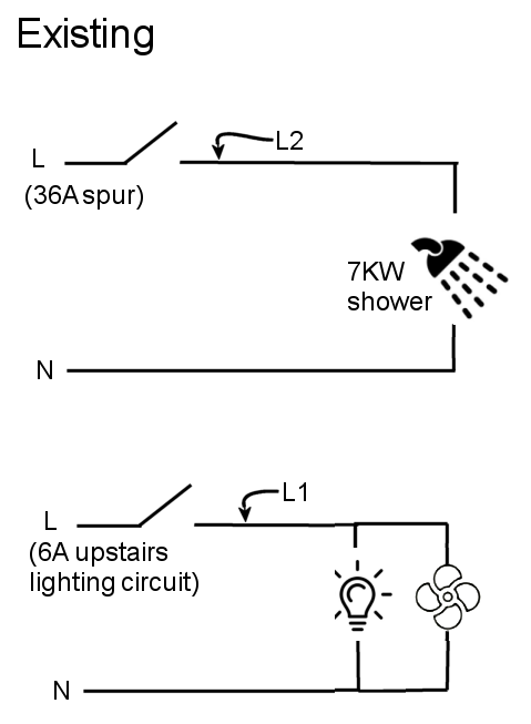 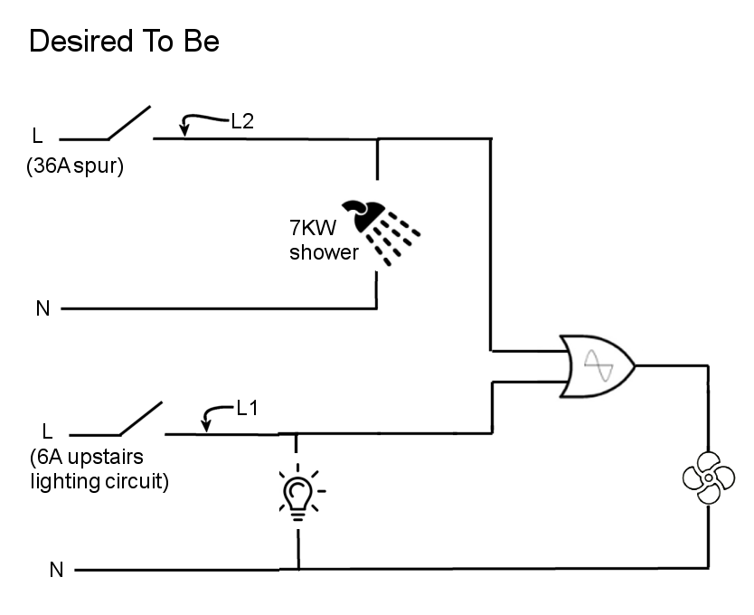 |
||||
| TassyJim Guru Joined: 07/08/2011 Location: AustraliaPosts: 5878 |
I forgot about your instant heat hotwater systems. They are very rare over here. If you can replace the light switch with a double pole switch with no and nc contacts it is doable. Not sure if they exist in domestic formats. 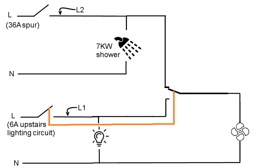 Jim VK7JH MMedit ┬Ā MMBasic Help |
||||
| CaptainBoing Guru Joined: 07/09/2016 Location: United KingdomPosts: 1985 |
Ah! now that is smart thinking, it is going back to the idea of the relay but using the light switch to do the grunt work. The light switch is a standard pull cord type and the actual mechanism in most switches is a SP changeover with a NC & NO output - fairly standard in light switches here. I will check to see if I can find a pull cord switch that supports two circuits - doesn't sound a big ask. Cheers Jim |
||||
| CaptainBoing Guru Joined: 07/09/2016 Location: United KingdomPosts: 1985 |
Hmm. well. Partial success. I knocked up the triac circuit today and it definitely acts as expected for functionality, i.e. Lc= (L1 OR L2). tested at full mains voltage with an 11W load. So the actual circuit I used was this: 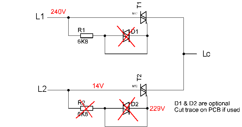 I don't have any diacs ATM so D1 & D2 were omitted. When a main input (L1) was live, I found there was a mains voltage on the other, disconnected mains input (L2) - so it immediately breaks the rule that it must not back-feed. I lifted R2 to remove any triggering and found that there was 229V on the gate and 14V back-feeding out of T2 MT2. Somehow the triac is self-triggering but it seems partial - where is that 14V coming from? I am at a loss as to why this is happening. Like I said, I am not a "power" designer and the only thing I can think of is that when T2 MT1 goes to mains, I am in one of the weird triggering modes of the triac and that results in current flow through the gate, back through R2 and then to trigger the triac at full potential. When I get more time I will put the scope over it to get a better idea what those voltages look like. Shame, but I am at the limit of my understanding of triacs. oh well, not the first show-stopper I've encountered and an enjoyable afternoon just the same. I have some BT3 diacs on the way - I will try again with them in circuit but I can't really see how they will help. Vbo of ~32V is easily whacked by the 229V. Edited 2022-04-25 06:25 by CaptainBoing |
||||
| phil99 Guru Joined: 11/02/2018 Location: AustraliaPosts: 1768 |
1. The self triggering of the triac with an open circuit gate is likely due to capacitance between MT2 and gate providing gate current. This effect is reduced by adding a bleed resistor (10k) between MT1 and gate and by adding a "snubber" from MT2 to MT1. It shunt transients away from the internal capacitance, a 100nF and 100R in series is usual for a resistive load. For an inductive load such as a fan I have found 220nF in series with 2k2 is more reliable. 2. As you have found the diac serves no purpose on its own. Its purpose is to discharge a capacitor into the gate to provide reliable triggering, especially for triacs with low gate sensitivity. In your circuit a 10nF should be connected from the junction of the resistor and diac to MT1. The diac has a "breakover" voltage of about 30V, switching from insulator to conductor and dumping the capacitor charge into the gate. 3. As you have found whenever one switch is on and the other off both triacs will switch on. The path through the "off" load (water heater or light) to neutral provides the voltage to switch the second one on. You can't make a simple AC equivalent of a diode OR gate with triacs alone. A more complicated triggering arrangement will be needed. |
||||
| phil99 Guru Joined: 11/02/2018 Location: AustraliaPosts: 1768 |
1. The self triggering of the triac with an open circuit gate is likely due to capacitance between MT2 and gate providing gate current. This effect is reduced by adding a bleed resistor (10k) between MT1 and gate and by adding a "snubber" from MT2 to MT1. It shunt transients away from the internal capacitance, a 100nF and 100R in series Āis usual for a resistive load. For an inductive load such as a fan I have found 220nF in series with 2k2 is more reliable. 2. As you have found the diac serves no purpose on its own. Its purpose is to discharge a capacitor into the gate to provide reliable triggering, especially for triacs with low gate sensitivity. In your circuit a 10nF should be connected from the junction of the resistor and diac to MT1. The diac has a "breakover" voltage of about 30V, switching from insulator to conductor and dumping the capacitor charge into the gate. 3. As you have found whenever one switch is on and the other off both triacs will switch on. The path through the "off" load (water heater or light) to neutral provides the voltage to switch the second one on. You can't make a simple AC equivalent of a diode OR gate with triacs alone. A more complicated triggering arrangement will be needed. Perhaps replace the diacs with pair of triac opto isolators or use a pair of SSRs. If you have easy access to the un-switched active on the light circuit only one may be needed. The cathodes of the IR LEDs go to neutral, 100uF caps from anodes to cathodes and series diodes and 100ks from anodes to the light and the heater. If your switchboard has safety switches cross connecting circuits will cause tripping. The single SSR or triac circuit should be ok. 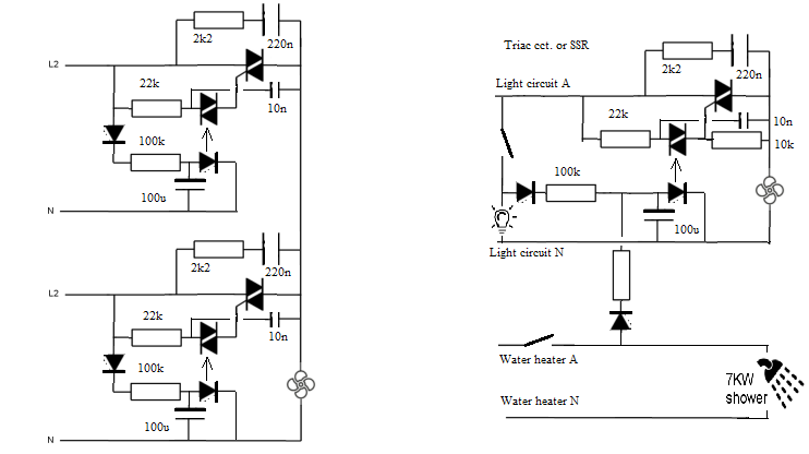 I have just noticed the triac gates are drawn on the wrong ends. Going senile, careless copy-and-paste. Edit. Why do these duplicate posts keep happening? Edited 2022-04-25 14:21 by phil99 |
||||
| CaptainBoing Guru Joined: 07/09/2016 Location: United KingdomPosts: 1985 |
Thanks for this Phil, it is good to get some insight on this. I never really "did" the triac thing other than for simple on/off control of a single circuit. I thought I was getting into dodgy waters when all my googling threw up nothing with using triacs like I initially thought. Should have taken the hint Ā You inherited that from my initial scribblings, no naughty-step for you. An early thought was rectifying the mains into a MOC3041(? I have dozens of the things that have followed me around for years) with a decent reservoir cap, but I was stymied by not knowing which mains circuit was providing the juice and no L3 available - that was the main "circle of doubt" where I thought I'd got it but then on further inspection I had introduced other problems... wish I'd paid more attention on "Triac day" when I was in college Ā The large size (and cost) of caps at these voltages also irked.I am going to continue to play for a while yet - it is fun getting knocked back and trying to work out why (but not as much as the darned thing working), but in truth this is starting to look like being clever for the sake of it. I have a DIN-rail mount mains DPDT relay which will do everything I want... it just feels more pedestrian, but as Mike said early on, "clunk is simplest". Plenty to think about here - many thanks h Edited 2022-04-25 15:53 by CaptainBoing |
||||
| zeitfest Guru Joined: 31/07/2019 Location: AustraliaPosts: 375 |
Just an idea - wire the fan to the switch. Wire the light to it via a remote "night switch" which goes open-circuit in daylight. |
||||
