
|
|
Forum Index : Electronics : Rewinding PJ8000 Tranny, Conflicting Winding Calculations
| Page 1 of 2 |
|||||
| Author | Message | ||||
| sunnypower46 Newbie Joined: 09/12/2021 Location: United StatesPosts: 24 |
I've stripped one of my PJ8000 transformers for a rewind. It's going to remain as a 24 vdc system under future EGS002/8010 control. I'm getting widely different turns numbers depending on different calculation formulas for the high voltage (secondary) section. I've determined the core area (A) to be 25.2 cm2. It's suggested to overwind the secondary, so my winding fiqures for a desired 240VAC/60Hz system are based on 260VAC. Using the Rule 42 method, I get 1.66 turns/volt (42/25.2 = 1.66). This would be 1/1.66 = .60 volts/turn. This works to 1.66 x 260 = 432 turns. Using a respected source from 'another' forum, the winding turns would be calculated as 2520mm2/2800 = .90 volts/turn or 1/.90 = 1.11 turns/volt. This would be 289 turns. I'm aware of the higher copper losses vs lower idle current impact; but still, the results are significantly different. I would tilt toward lower idle current as my nightime loads are under 2.5 KW. During daytime, my microinverters (4KW) supplement my main offgrid inverter output and/or backfeed excess energy to charge batteries under dump load control. FWIW, I found a source that suggested volts/turn at 60Hz vs 50Hz should be expected to be 20% higher. If true, that could further alter the calculation results. I expect both the winding formulas I have are based on Australian and Chinese sources (50Hz). Not sure what to do. Help! |
||||
| Solar Mike Guru Joined: 08/02/2015 Location: New ZealandPosts: 1123 |
Use this Flux Density Calculator Plonking in: AC Voltage = 240 Freq = 0.000006 (60 HZ) Area = 25.2 Turns = 370 Adjust the number of turns to achieve under 10,000 gauss flux, this will give you low core loss. 370 seems to work out ok Cheers Mike |
||||
| sunnypower46 Newbie Joined: 09/12/2021 Location: United StatesPosts: 24 |
Thanks, Mike I'll check it out. |
||||
| sunnypower46 Newbie Joined: 09/12/2021 Location: United StatesPosts: 24 |
First, a simple correction to Solar Mike's response: 60Hz is 0.00006 Mhz for the calculator's entry. An obvious posting typo. The 370 turn result is correct. Is it appropriate to overwind for 260VAC as recommended by some, or does this formula provide extra margin if designed for the intended 240VAC operation? If designed for 260VAC, the turns goes up to 388. What drives the 10,000 gauss flux limit? I'd like to learn more about the subject. Any good resource links? I stumbled on an additional Chinese site discussing toroid windings and it basically was promoting a Rule 36 formula. Even less turns needed. Finally, anybody had any practical experience with the results from this calculator? |
||||
| Solar Mike Guru Joined: 08/02/2015 Location: New ZealandPosts: 1123 |
10,000 gauss (1 Tesla) is very low for modern well made silicon iron laminated cores, which can top out at 1.8 Tesla; so if you design at 1 Tesla flux density and the expected voltage - frequency using that calculator, you should end up with a low loss setup. Increasing the voltage with other "Rule of thumb" formulas is just another way of adding more turns which lowers the flux in the core. There have been many past topics here on the forum concerning winding toroidal cores, do a search for a key words like "Flux Density" and you will locate them. Cheers Mike |
||||
| sunnypower46 Newbie Joined: 09/12/2021 Location: United StatesPosts: 24 |
Alright then, I think you're saying design/build for 240VAC (370 turns) and the formula will take care of me. I'm apprehensive because the secondary turns will be spread with expoxy and thus offer no chance for redo. Not too worried about the primary winding. For EGS002/8010 control, I think the primary voltage recommendation is 14-15 vdc (24 volt system). I can play with those turns as needed. Thanks for the "flux density" word search suggestion. I'll look through some posts. For others coming to this post, let me offer some insight on what I found when stripping my PowerJack 8000 toroid (circa 2015?). It had been running 24/7 since then with toroid temps ranging 35-65C. I remounted it vertically resting on two wood dowels covered with 1/2 inch ID silicone tubing (cushioning). An added large round fan directly blows 300 cfm air around and through the 'doughnut'. It's probably the best cooling design you could put in that enclosure. A literal windtunnel. But, I had to 'put this tranny down' because some secondary turns shorted and melted. While unwinding, I found the primary to be about 21 turns of 8 in hand 12 awg wound over mylar wrapping that insulated it from the secondary. So far, so good. The secondary was the weak link in this tranny. Just two overlapping layers of a single 14 awg to provide about 360-370 total turns. The core had an insulating paper inside the inner core and over the outer core diameter. It was charred and flaked away. The core wasn't continuously wrapped around with any kind of protective tape. There was no effort to insulate between the double 14awg layer. Just wire over wire and no protection at the sharp edges of the toroid core. No expoxy anywhere. Amazing it performed this long. Expand-contract-expand-contract-BOOM! My unit was a split (tapped) secondary (120-0-120) American version. Only one of the three PJs I bought was ever close to having equal voltage on the split windings. One was 112-0-126, which I had to "fix" with a buck winding over the toroid. I guess the winding machines can't count turns . . . . . . The metal toroid core is interesting. Not a continuous length of metal wound into a core. Many smaller lengths of metal creating an overlapping flap type core. Again, no epoxy binding anything together. High quality silicon steel? No clue. So there you go. Are they building any better ones today? Draw your own conclusion. My unit gave faithful service for as long as it could. Overall, I'm satisfied but disappointed with its untimely demise. |
||||
| Solar Mike Guru Joined: 08/02/2015 Location: New ZealandPosts: 1123 |
I did infer "Quality" core material for that, perhaps your multiple overlapping core layers could be made from anything some back yard builder had on hand; so quality is a definite unknown. You could roughly wind on say 100 turns and connect a variac to it, starting with a low voltage, increase the voltage and measure the AC current. At some point the core will start saturating and the current increase exponentially; graph it to see the trend. Now you will know the best number of turns to applied voltage and be able to set it for your 240. Perhaps NOT if made in China or India etc; there are manufactures of these cores, certainly in NZ there are, I got my bare cores made to the size requested, they came back encapsulated in a clear nylon (dipped). Cheers Mike |
||||
Haxby Guru Joined: 07/07/2008 Location: AustraliaPosts: 418 |
One Tesla isn't a limit per-se. It's what we try to achieve to keep idle current as low as possible. As stated above, you can wrap say 10 turns on the empty core and energise with one turn per volt=10vac and see what the core losses will be. These core losses won't change with a fully wound transformer. Now: the big question: How many conductors fit through the toroid you have? this link shows how many conductors will THEORETICALLY fit. PJ transformers are very small and over rated. Why not buy a bigger transformer and start from scratch? There are plenty on eBay. If the PJ transformer is made of small chunks of steel, it may be inadvertant or may be done on purpose to magnetically decouple the primary and secondary windings. This makes regulating the voltage harder but has the benefit of not stressing the MOSFETs as much as a tightly magnetically coupled transformer. |
||||
| sunnypower46 Newbie Joined: 09/12/2021 Location: United StatesPosts: 24 |
I appreciate these practical ideas. Well, now I have an excuse to buy a variac. How far back from the "exponential current increase" is the sweet spot? What impact if too close or too far back? Feel free to offer a resource link if it's easier to answer. @haxby: Your core loss info gives me a starting point. I can make use of 12 or 24 VAC transformers to excite the winding until I get a variac to refine things using solar mike's approach. So, measure AC current at the applied voltage and determine wattage loss? I used a similar link to figure conductor fit for the primary turns. It's doable for the power I need. PJ used 8 in hand #12. I'm thinking 12 in hand #14. I'd really like to use flexible welding cable but it closes off the core too much for good airflow. And the biggest cable that will fit is around #4. Also, it's far from being "close coupled", if that matters much. I think all the reasonably priced large cores are being held captive "down under"! Tough to find on Ebay at the "top of the world". This is more an educational exercise in toroid building for me. The PJ core is my experimental tool. I know it's limiting. Gotta walk before running, though. What I'm after is getting the most from this small core with a minimum of turns, reasonable (not necessarily lowest) idle current and a nice waveform from a 24vdc (lifepo4) 8010 controller under varying loads. So, I guess I play with the turns per volt at a given (low) voltage until I get to my acceptable core loss. |
||||
| Haxby Guru Joined: 07/07/2008 Location: AustraliaPosts: 418 |
There are lots of near-identical threads in this forum for practical rewinding of transformer design tips. Have a read of this thread, particularly anything/everything Tony (Warpspeed) said. What Tony says might as well be the Bible of transformer design. And Rogerdw has the best practical techniques of winding transformers neatly. Looks like you are on the right track. It's a LOT of work to wind a transformer. If you are in the US, look up "Lenco Electronics Inc. 5KVA Transformer" on eBay. There is a seller that has a few. For $60 each, if I was in the US, I'd buy all of them up. There was a discussion on this forum how to wire them for 24v use here I just think it's too much work to get the PJ transformer working again when there are bigger and better transformers on the market. One more note: A neat trick we do on this forum is to glue 2 identical cores together. One on top of the other. This gets the volts per turn and flux density right down to the theoretical minimums. And this makes for a large cross section area. The idle power gets down to 30w or less for a 5kw transformer. Not sure if you can source another PJ transformer to do the same. |
||||
| sunnypower46 Newbie Joined: 09/12/2021 Location: United StatesPosts: 24 |
I found the Lenco Ebay listing. Thanks! And I want to study the 24v usage link further. I'm probably going to talk myself into one ... or two. Seems worth it for the core alone. Wish I could drive up there and save the shipping; but, it's too far to justify on a gas cost basis. I'm near LA, Lenco is near Sacramento. The "practical rewinding tips" link is treasure of information. I've got to go through it again and sort through what applies. The PJ transformer is all rewrapped and ready for new wire, which was purchased earlier. I'm too far into it to give up now. I have two more PJ transformers, only one still working, though. Might glue two together at some point. Seems silly if the Lenco cores can be used, though. I ordered a variac to try the suggested testing. I'll be back with some data in a week or so. Stay tuned! |
||||
| sunnypower46 Newbie Joined: 09/12/2021 Location: United StatesPosts: 24 |
Been looking at that Lenco drawing. It appears the potting core is around 62mm diameter. Assuming that could be knocked out, would you want to guess the multiple 20v windings are wound on top of the two 120v windings? If they did it that way, it should produce a physically smoother winding result. That's the way I would do it if working with just a bare core. Stripping off the multiple 20v windings would open up the core for a new primary with the optimum turns. I could work with that. I've put 50 turns of salvaged wire on the PJ tranny. Just waiting for the variac to arrive and do some testing. |
||||
| Haxby Guru Joined: 07/07/2008 Location: AustraliaPosts: 418 |
Did you carefully read the discussion in the forum link I provided in my last post? It talks about configuring that exact transformer on 24v AND decreasing idle power at the same time by decreasing the flux density. We talk about adding one of the 20v windings to the output. For split phase in your case, you could add two of the 20v windings to the output. One on each phase, to decrease idle power even more. No need to modify the transformer and it will be oh so much better than the PJ transformer. |
||||
| sunnypower46 Newbie Joined: 09/12/2021 Location: United StatesPosts: 24 |
There's a difference between reading and comprehending it all, though. Some of my fundamental knowledge of transformer operation needs a boost. I'm having to read between the lines a bit to get to your conclusion. Transformer operation is not my strong suite. It's all about the final turns ratio I get. Right? So, taking two of the eight primary 20v windings and correctly pairing them with the existing 120v windings gets me a 260v (center tapped) secondary. Now (thinking backwards), if I energized the winding on the new secondary with only 240v, my primaries would drop to less than 20v. Reducing the new secondary applied voltage from 260v to 240v (7.7% reduction) should drop the primaries to 18.5v (?). If correct, that's somewhat high for a 24vdc 8010 controller, which I understood to want a primary around 14-15vdc. I guess I make it work by playing with the 8010 voltage feedback adjustment to get my 240vac. Dynamic range would suffer, but not as much an issue with lifepo4 batteries. The remaining six primaries are to be wired correctly together in parallel, offering an effective 189A (6x31.25A) winding. More than adequate for my needs. If this is the way it shakes out, it looks promising. What have I got right/wrong? Anyway, the suggested 5KVA tranny is on it's way to me. That's going to have to wait in the toybox for later fun, however. Meanwhile, I wrapped fifty turns of wire on the PJ toroid core and used my new variac. The resulting curve suggests 1V/turn would not be overly lossy. So, 120+ turns either side of centertap is the number? At 50v applied I noted .53A on the clamp meter, about 21 watts. Getting into saturation further really hits the amps and sound hard. This was a worthwhile learning experience for me. If I can get this photo of the curve into the post, all can have a look. 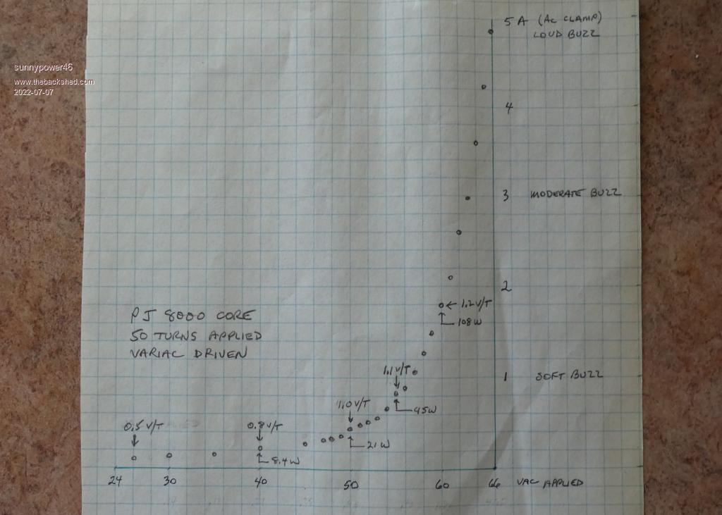 |
||||
| Haxby Guru Joined: 07/07/2008 Location: AustraliaPosts: 418 |
You are very much on the right track. The turns ratio calculation is easy. The question is how much lower can you go than 1v per turn to really optimise the idle current. Each turn uses up space in the hole. You want as many turns as possible with the least amount of volts per turn. From your graph, you could try aiming for 0.8v per turn, so 20% more turns than a 1v per turn transformer. Will it fit? Maybe. That's where the hole in a hole calculator will give you a rough idea. The other rule of thumb is that the cross section area of the conductor will give you the current rating of the winding. The rule is 4 amps per square millimetre. You can probably see now that the most optimum transformer is going to have a lot of windings around it, and pretty much no space in the hole left. The gurus on this forum take things further by doubling up on the cores. This decreases the volts per turn even more. For the 5kva transformer, you are right that the 18.5V winding is a little too high. It would be better if it was lower. What's the lowest that your batteries go while discharged? You could sacrifice another 2 X 20v windings (put them on the primary) but that starts to limit your power. Is that an issue? Or you could take out the core carefully and add a few turns on the low voltage side. Each turn will be about 1v, so just a few turns should do it. Another dirty trick is to change the regulation circuitry of the inverter as the battery gets low. You might want 120v AC per phase with a strong battery but might want to dial it down to 110v or less with a weak battery. The benefit of having two regulation settings is that you can switch to the lower setting at night. This will decrease the volts per turn and make the transformer more efficient over night when there is no solar available. |
||||
| sunnypower46 Newbie Joined: 09/12/2021 Location: United StatesPosts: 24 |
The 240v center tapped output (secondary) will need a total of 2+ layers - each 120v winding will be one full layer (100 turns?) plus at least 20 turns over the other 120v winding; depending on the 0.8 - 1.0 V/turn decision. So, not over 3 layers of total secondary wire on the PJ rebuild. I'll know my inner hole diameter after the secondary is in place and go from there. With a single 14awg secondary wire this thing won't be any better than the original PJ unit; maybe 2.5-3KW solid with my cooling system. That's ok. That worked and covered my needs for over four years. It's all I need from this rewinding. I'm just hoping to have a more reliable transformer than their original build. I think my original analysis of the 5kva reconfigured transformer was incorrect. Adding a 20v winding to each 120v existing winding gets me to a 280v (not 260v) secondary. Energizing this 280v new secondary with only 240v forces a 16% reduction against the 20v primary. So, now looking at 16.8v. Is that making this a little better. I won't let the batteries (600AH total) go below 24vdc. Love the flat discharge curve of lifepo4. Adding another pair of 20v windings pushes the secondary to 320v. Running that at 240v is a 25% reduction in the 20v winding -- 15v. But, I'm down to a 125A primary winding. 3000W at 24vdc. Not sure that's gets me much better than the PJ, but it provides a nice backup transformer on site for another inverter build. If I opened up the transformer, I was thinking I needed to reduce the existing number of primary turns on the 20v windings. Increase the turns ratio. ??? |
||||
| Haxby Guru Joined: 07/07/2008 Location: AustraliaPosts: 418 |
Ok if minimum battery voltage is 24v then Secondary windings should be 24v/(sqrt 2)=17v Maybe subtract another volt or two for the voltage drop in the MOSFETs. So 16.8 as you calculated, is workable. It will be a little high, but I'd suggest instead of 120v outputs, adjusting to 110 to 115v outputs, which sways things back in your favour a little. Yes you could unwind a few turns. Personally I would try to leave the transformer as-is. But that's just my opinion. I don't fancy winding transformers, and with multi-tap transformers like this, it can get messy. |
||||
| Godoh Guru Joined: 26/09/2020 Location: AustraliaPosts: 378 |
I would advise checking on the requirements for the 8010 board as far as transformer voltages go. I rewound the secondary on a PJ transformer to use a Sunyima 8010 board. The sunyima specs stated a 12 to 14 volt primary for a 220 secondary. I ended up adding some turns to the secondary to give me a 260 volt output and made the primary 14 volts. PJ seem to have odd voltage ratings that don't relate to the real world, just like their power ratings. To get the 8010 board to regulate the output properly you need around 260 volts output. Have fun Pete |
||||
| Haxby Guru Joined: 07/07/2008 Location: AustraliaPosts: 418 |
When it comes to voltage drop in the transformer, when under max load, there are "rigid-coupled" transformers and "loose-coupled" transformers. Good quality "rigid-coupled" transformers won't need much feedback to maintain regulation. They are like a mack-truck. Whatever input voltage is applied, will be tightly magnetically coupled, and stepped up by the turns ratio. There will be some losses at high output power, but not a lot. Poor quality "loose-coupled" transformers on the other hand, act more like a resistor under heavy load. The output voltage droops more, so they have to be built with more secondary windings. This is done so that they don't run out of head-room to regulate. They are smaller than the rigid-coupled transformers for the same power size, and will heat up more. The sine wave is hard to control, as the feedback circuitry is constantly fighting a sloppy spongy transformer between the inverter and the load. The Sunyima boards are good, but Sunyima doesn't know what the characteristics of your battery is, so they can't tell you exactly what transformer voltage to use. It could be lead acid, LiFePo, LiPo, etc... So you should always choose the lowest voltage that your batteries can supply for all of your transformer calculations. If it regulates well at the lowest battery voltage, it will regulate well at higher voltages. |
||||
| sunnypower46 Newbie Joined: 09/12/2021 Location: United StatesPosts: 24 |
The 5KVA transformer arrived. It's a beast. Good condition. No time to play with it now. If I have to, I'm not sure the center potting can safely be "knocked" out. Probably will take some careful surgery first to reduce the side force tension. I'm going to shoot for a 16:1 ratio for the PJ rewind. 240v secondary, 15v primary. Using the 0.9 turn/V value, from earlier, I figure 267 secondary turns and 17 for the primary -- what I hope will be a reasonable balance of the various options suggested. After winding the first layer, I've got at least a 68mm inner diameter remaining. With only a 50mm diameter hole, I've determined I can get up to 21 turns of #4 awg welding cable in there. The hole diameter will likely be around 60mm or better after the next secondary layer is wound. So, maybe even #2 awg cable will fit. Failing that, I have to go the many wires in hand route. Yuk. The first layer of #14 awg accepted 122 turns. I need about 134, so some overlapping will be required. That would then produce the 120v half of the 240v center tapped total. Repeat for the other half. I know I'll get less turns wound on the second layer. I'll deal with that on the third layer. Some pictures to share. First. All 122 turns. Wrapping with 3/4 inch fiberglass window screen strips I cut. High heat resistant, easy to work with, somewhat stretchy, allows you to move the wires underneath, if desired, before epoxy. Second. Readily accepts epoxy. I'm using a high heat resistant (425F) "casting" epoxy. It's a bit too thin. Has a several hour working time. Next time I'll wait till it thickens up some, like peanut butter. The screening was supposed to resist its running, but couldn't meet the challenge. The epoxy curing time is slowing my work down. Wouldn't a high heat, fast setting, thick coat spray on epoxy be nice! Third. Closeup. The screening provides a physical barrier of sorts for the next layer. Better than a direct contact second layer, at least. I'll do better with the epoxy on the next layers. 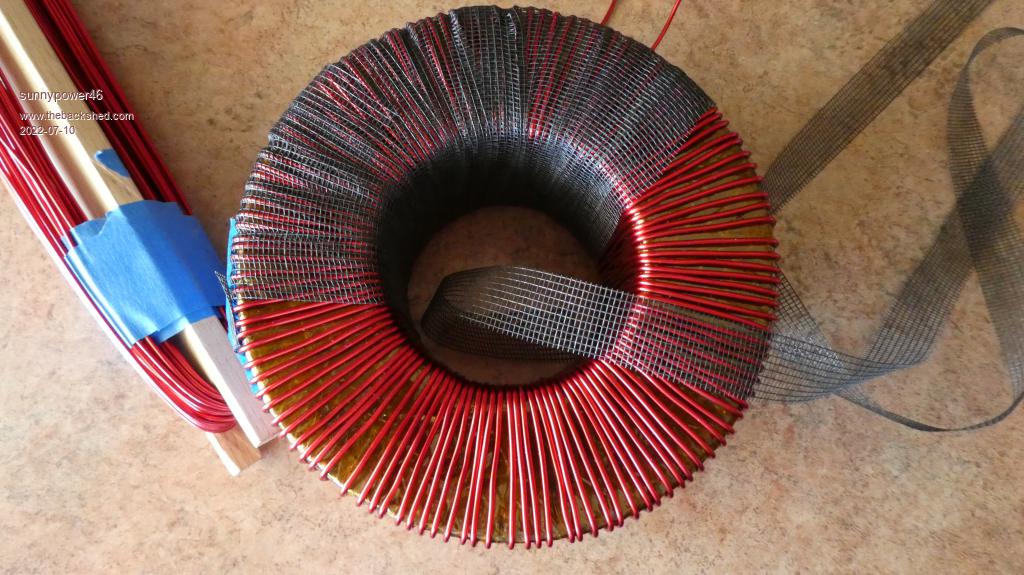 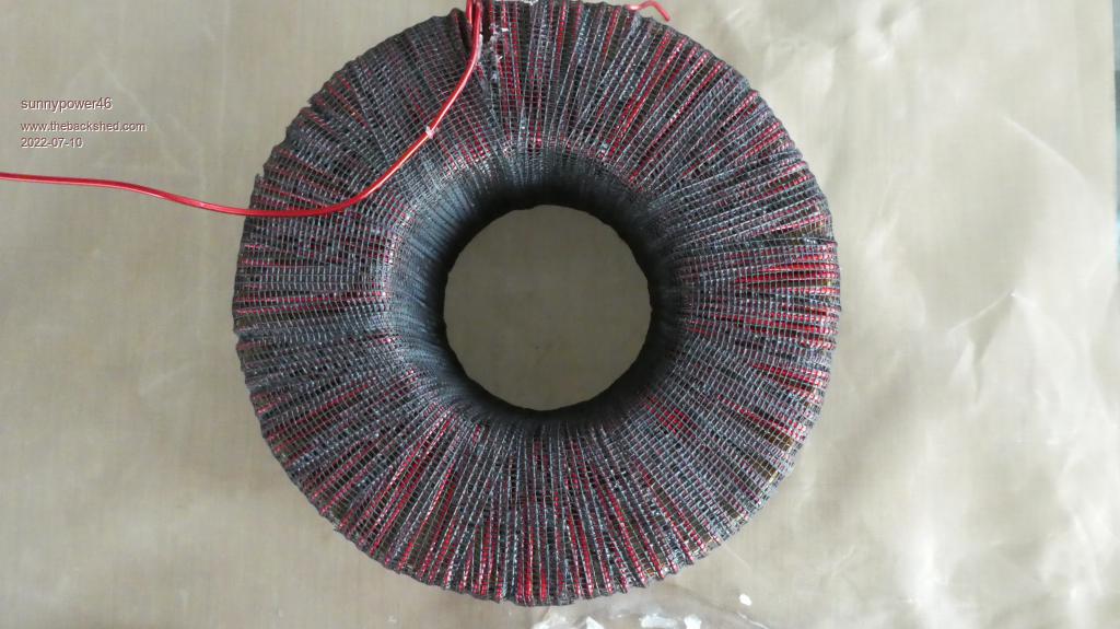 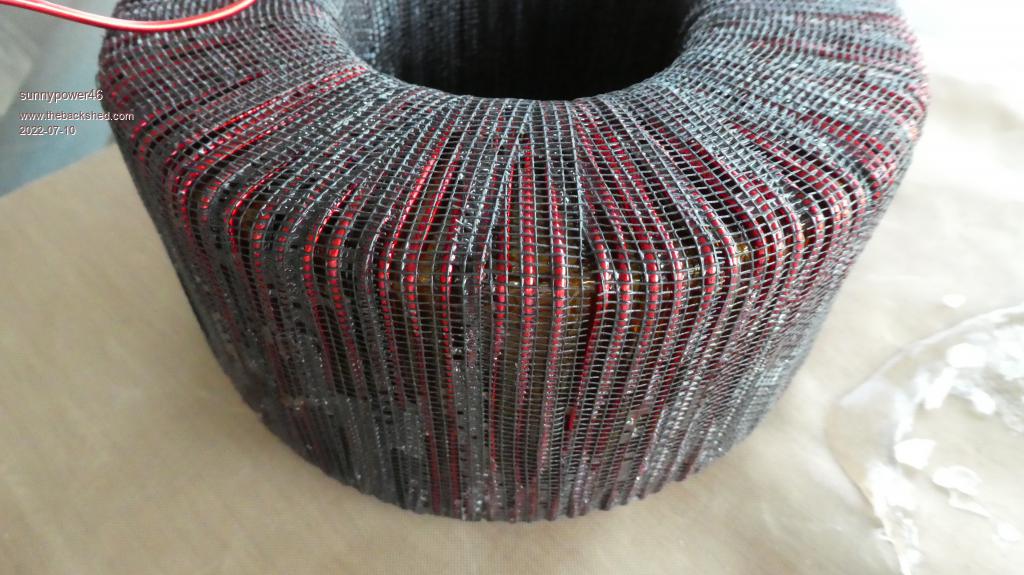 |
||||
| Page 1 of 2 |
|||||
