
|
|
Forum Index : Electronics : Mosfet Testing Jig
| Author | Message | ||||
| Solar Mike Guru Joined: 08/02/2015 Location: New ZealandPosts: 1122 |
I need to test 100 or so used TO263 mosfets, purchased off AliExpress very cheaply. Expect some are not working, but as they have been snipped out of old equipment, they appear original, so hopefully ok. Main requirement is to measure the Drain Source resistance under load. So I need a test jig that clamps the surface mount device to measure, these devices are quite small and fiddly, unlike the TO247 devices that have long legs to clamp too. Have � made a 100 x 100 pcb to accommodate all the bits. A 12 volt variable PSU will be used to power it and 3 x 4r 100W metal shell resistors in parallel as a load. If I use 10 amps as the load, then its easy to convert the mV drop across the Drain-Source pins to ohms. Mount the pcb on an alloy heatsink with the power resistors, may need a small 12v fan, will see. Using a large copper pcb terminal with a 4mm bolt to clamp the mosfet down and couple of 4mm brass bolts with copper washers and a knurled nut to clamp the other pins Alternative to to wait 18 months - 2 years to get an order off Element14, its almost impossible to get any semiconductors now, even some resistors are 12 month back ordered. No circuit for this, pretty simple, may make a clone for doing TO247 devices. 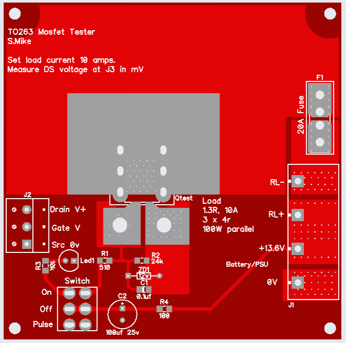 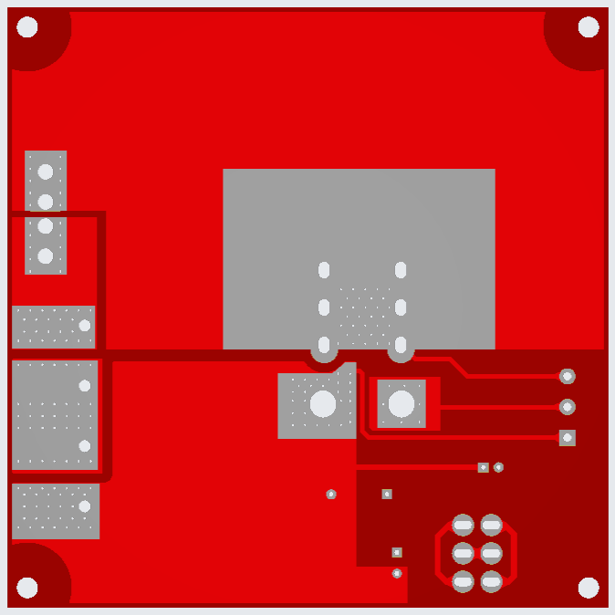 Edit: updated the gerbers to have incorrect J3 wording changed to J2 Gerbers_Tester263.zip Cheers Mike Edited 2022-07-31 14:23 by Solar Mike |
||||
| Solar Mike Guru Joined: 08/02/2015 Location: New ZealandPosts: 1122 |
TO247 version, was only a few minutes work to create. The mosfet to be tested sits on a 3mm thick copper spacer clamped by a bolt and wing nut; pins clamped by 15A rated 3pin socket.   Gerbers_Tester247.zip Have a few dodgy suspect fake to247 devices here from past inverter builds, be interesting to check them out. Cheers Mike |
||||
| gaspo Regular Member Joined: 25/06/2018 Location: AustraliaPosts: 61 |
Nice boards Mike, I might use your gerbers next time I order something from JLCPCB. For now I use something simpler for TO247 �  � �PSU set to 10A CC and 12V adapter for the gate. The HY5608W measures nice 1.36m?. 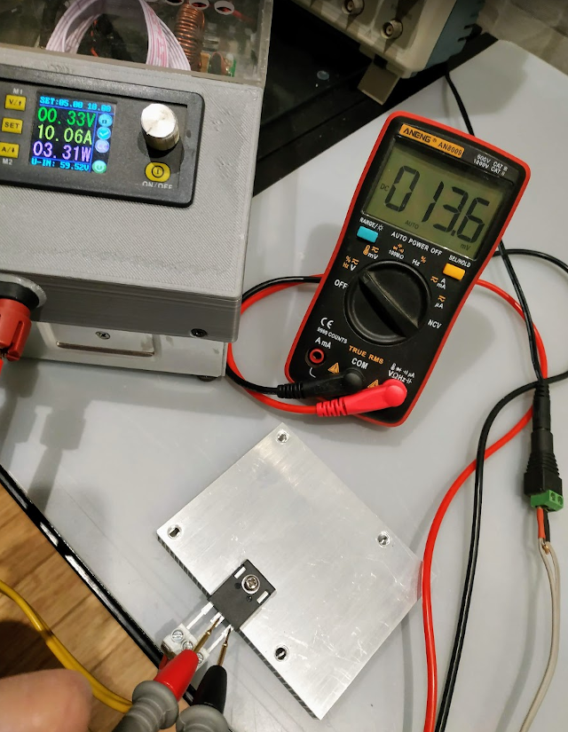 Edited 2022-08-01 23:51 by gaspo |
||||
| rogerdw Guru Joined: 22/10/2019 Location: AustraliaPosts: 792 |
Hi guys, I've been going to ask for a while ... when you measure the Drain Source resistance under load ... do you take the first reading you get or do you wait for a few seconds or longer for it to settle down. I was trying to get a fairly quick reading, but if I measure them again after a while, they are usually all quite different. Thanks. Cheers, Roger |
||||
| Murphy's friend Guru Joined: 04/10/2019 Location: AustraliaPosts: 580 |
Roger, its 'very' important to place the probe tips exactly at the same place each time. As seen in Gaspo's picture, right against the Cmos body. If you have it on a heatsink it should not get warm enough to change the reading if it's on a heatsink (good idea with 10 Amps  ) )It's also worthwhile to test the switching ability of the mosfets. For that I made a little tester that turns the gate on and off with a selectable square wave and use a 12V automotive light bulb for a load. |
||||
| rogerdw Guru Joined: 22/10/2019 Location: AustraliaPosts: 792 |
Well after all this messing around trying to match Rds-on ... I'm starting to think it's a waste of time. I set up a 10A current limited power supply and used a terminal block to screw down the 3 mosfet terminals. I set up one of those quick acting clamps (with rubber feet) in a vice on my bench so I could put a consistant pressure on the mosfet body. I went through a couple dozen and occasionally went back and rechecked an earlier one to make sure I was being consistent. Then decided to have a coffee and a bit of a break and came back to do some more. Immediately the readings were 5-6 miliohm lower generally and after doing another couple dozen I gave it away. This morning I tried again, and the readings were consistantly 13-14 miliohm lower than last night. Realising it must be temperature related, I started measuring the temp ... and found that even a degree or two would have noticeable effect. A 1 second burst of freeze spray on the mosfet edge under my clamp lowered it 8 miliohm ... and then 5 good breaths of warm air a couple minutes later had it up 10 miliohms. So far I've only been using solar mikes board ... and I know my fingers are not calibrated, but at no stage could I perceive any rise in temperature of the board. Maybe I'll use one of those huge aerosharp heatsinks and clamp down on that ... then regularly check the temperature ... and do them all in one sitting. Not convinced it's even worth it though. Mmmm!!! Cheers, Roger |
||||
| poida Guru Joined: 02/02/2017 Location: AustraliaPosts: 1387 |
Rds(on) is greatly effected by temperature. For example, the IRF3710 (100V, 57A, 23 mOhm) has this as it's Rds(on) v temp  "Normalized" means the left hand axis is "1.0" = 23 mOhm and so "2.0" = 2x 23 mOhm or 46 mOhm at 25C it's at 1.0 or 23 mOhm. At 80C it's 1.5 or 50% more resistance. These temperatures are at the junction. Not the case temperature. The junction is always a lot hotter than the case. Again, looking at the IRF3710, the thermal resistance from junction to heatsink (with a good flat surface and thermal grease) is 1.25 C/Watt so with a huge heatsink at 25C, the junction will be 1.25 C hotter than that for each Watt dissipated. HY4008 is better, it's 0.4 C /Watt junction to case. But it works both ways, a little heat or cool applied to the case goes straight to the junction. You saw this with the small heat and cool tests. here is the HY4008 Rds(on) v temp curve. 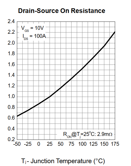 It's nowhere near as sensitive as the IRF3710 but it's still going to change due to temperature wronger than a phone book full of wrong phone numbers |
||||
