Notice. New forum software under development. It's going to miss a few functions and look a bit ugly for a while, but I'm working on it full time now as the old forum was too unstable. Couple days, all good. If you notice any issues, please contact me.
Murphy's friend Guru Joined: 04/10/2019 Location: AustraliaPosts: 583
Posted: 09:43am 19 Sep 2023
Copy link to clipboard
Print this post
This idea came to me after using IPTC14N0NM5 mosfets for my one shot inductor saturation tester. These mosfets have an incredible low Rds on of 1.4mOhm max, beside 100V & 365A ratings.
The following is based on a heatsink measuring 100 x 100mm with 6mm fins (ex. Aerosharp).
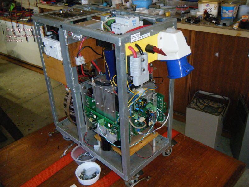
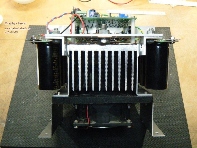
I used my 3KW inverter as a testbed, here is what it looked original:
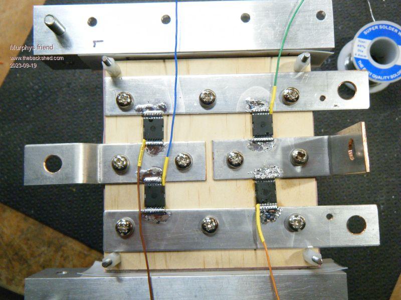
These mosfets have all drain pins on one side and the source plus gate on the other:
They were soldered upside down between 16 gauge copper strips:
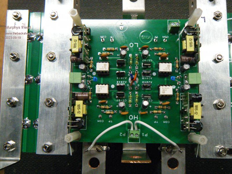
On top of that fits the driver board:
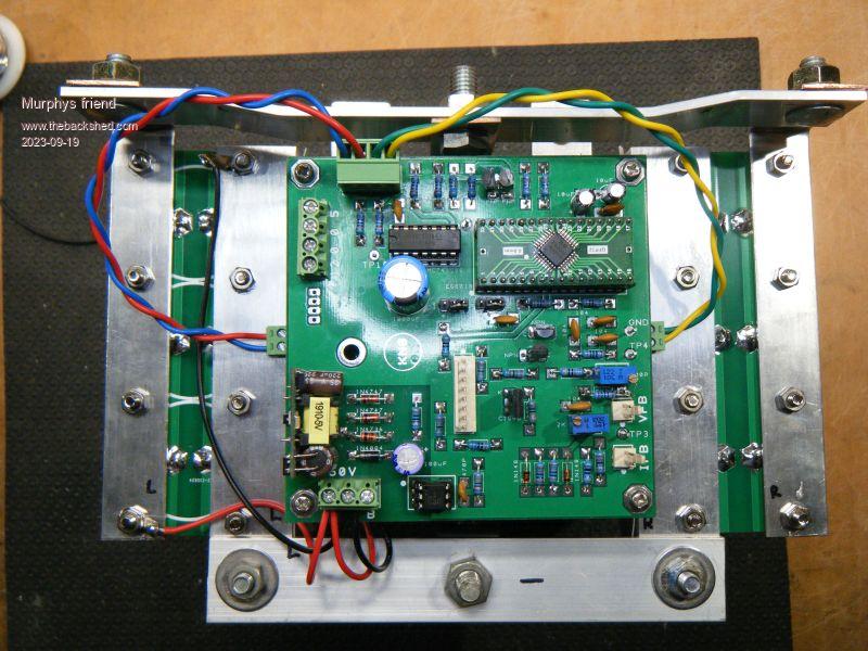
Followed by the control board:
A side view of the power block:
All boards are 100 x 100mm BTW.
Ready for testing:
Comparing old and new size difference:
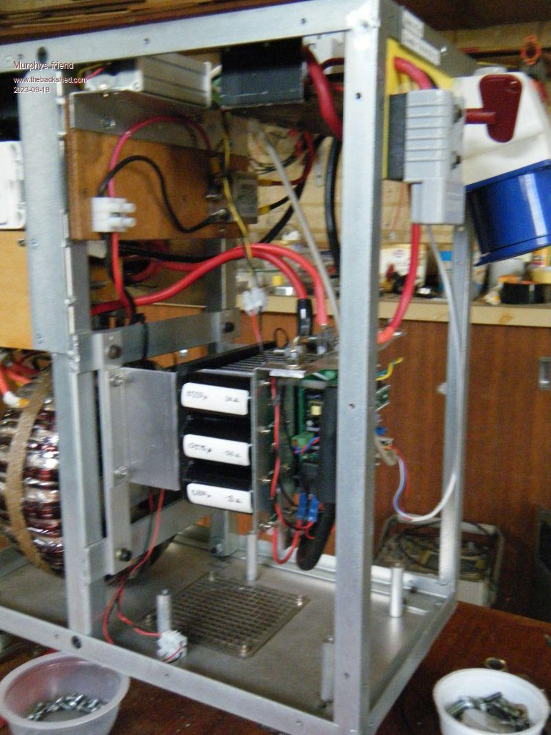
Lots of space in my inverter now:
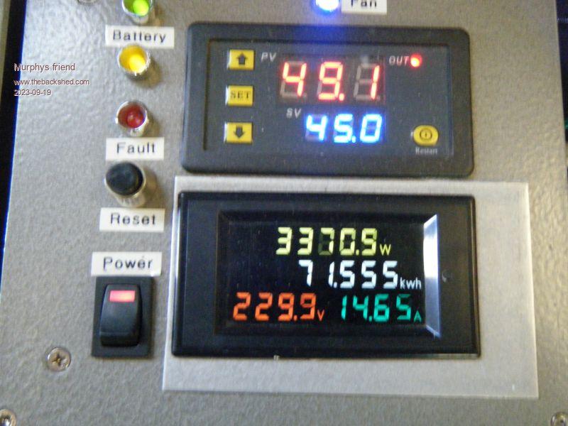
Now for some testing. I first tried powering it flat out, keeping in mind the inverter has a 3KW toroid transformer. It handles that power easily:
Ambient temperature was 21 degrees C, the 90mm fan came on after about 10 min (at 50 deg. heat sink) and easily cooled the heatsink down to 45 degree from where it cycled then.
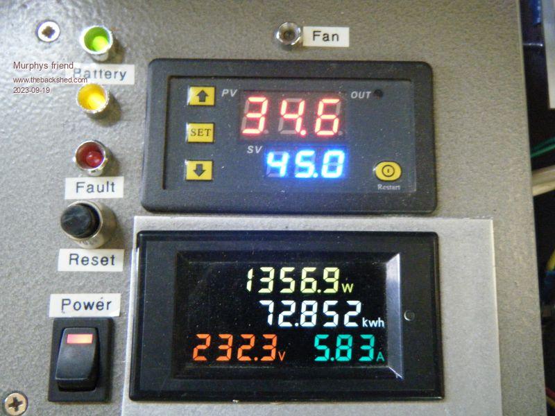
After 2 cycles I reduced power to:
A which the heatsink kept cooling, the temp. shown above is after one hour running. By this time the sun got too low to continue testing without draining my battery bank.
So, for my normal power use this small heat sink would be adequate, it appears. Summertime testing will confirm this.
Those 4 mosfets should easily handle a 6KW load with a heatsink perhaps twice as big. That's still a lot smaller than my 6KW inverter uses now.
Another advantage, my 3KW inverter just got 5kg lighter
Solar Mike Guru Joined: 08/02/2015 Location: New ZealandPosts: 1123
Posted: 10:56am 19 Sep 2023
Copy link to clipboard
Print this post
Impressive spec's, looked up the price $12 odd in 10 off quantity, did you manage to locate a less expensive source?.
I wonder how that configuration would work if the copper bars were replaced by 15mm copper plumbing tubes with water running through; small circulation pump from a CPU water cooler kit and radiator mounted in the case wall; make it more compact.
Cheers Mike
Murphy's friend Guru Joined: 04/10/2019 Location: AustraliaPosts: 583
Posted: 01:53pm 19 Sep 2023
Copy link to clipboard
Print this post
Mike, you can buy 4 of these mosfets for just over $50.- which gets you in the free delivery range from Element 14. I bought mine there in a lot of 4.
I think it would be difficult to solder these tiny (10mm sq) devices to tubing without shorting the gate pin. What I'm doing for the next one is to use a 2oz PCB with square cutouts for the 4 mosfets. 1.6mm PCB is just the right thickness for the top (heat conducting) face of the mosfet to touch the heat sink insulator below if its soldered facing through the cutout. I'll bolt 15 x 2mm copper strips on top to cater for the current, this also helps with heat transfer.
If you wanted water cooling you could run small tubes through the heat sink but I think fan cooling is quite sufficient for continuous high power. At 100A the mosfet has just 14 Watts heat loss (ideal conditions).
wiseguy Guru Joined: 21/06/2018 Location: AustraliaPosts: 995
Posted: 06:23am 20 Sep 2023
Copy link to clipboard
Print this post
Found it after a bit of juggling as IPTC014N10NM5
Klaus your pioneering spirit is noteworthy. I remember once (~1995) suggesting a TO247 pack as a replacement which had better specs all round to a similar TO3 variant. It was howled down as a "ridiculous" idea and the "plastic" part would "blow to pieces".
I spent the next 15+ years successfully using those TO247 devices in that specific application. However I am now having trouble reconciling your 3kW application using just 4 teeny 10mm x 10mm plastic SMD 16 pin packs that switch 375 odd Amps!
Not sure I would have ever done/tried it either - a bit of deja vu in reverse. But the engineering side of me says if the cooling and electrical connections are valid and the spec sheet is followed it should work, as you have now demonstrated, .
I wont be changing to them anytime soon though as for the same money each, it is still cheaper to use 3 or 4 HY5608's of which each one has essentially the same capabilities as one of the SMD parts & they also "look" much tougher too Edited 2023-09-20 20:14 by wiseguyIf at first you dont succeed, I suggest you avoid sky diving.... Cheers Mike
Murphy's friend Guru Joined: 04/10/2019 Location: AustraliaPosts: 583
Posted: 10:57am 20 Sep 2023
Copy link to clipboard
Print this post
Mike, I like tinkering with new things I come across.
Those teeny weeny mosfets I could not destroy when two of these in parallel got over 700 peak Amps dumped through in my choke saturation tester. No heat sink on them either.
So I thought they could be used for the power stage of an inverter with a relatively small heatsink. Did an endurance test today, 2 hours of powering 2050W of heater & flood lights raised that heat sink to 47 degrees from an ambient of 21 degrees. This was without the inverter cover fitted.
Then I decided to find out if that tiny inverter could start the caravan aircon. No, it could not, this obviously requires two mosfets in parallel. So, that is my next project, must keep myself busy.
The 'bang' event , BTW, was nothing special compared to the HY4008's I blew up in the past. Just the top of one mosfet split off, three of them are dead. Have to unsolder the 4th to see if its still useful.
nickskethisniks Guru Joined: 17/10/2017 Location: BelgiumPosts: 411
Posted: 07:08am 28 Sep 2023
Copy link to clipboard
Print this post
Cool mosfets and another piece of art!
Small question, I can't find the source wires, how did you connect those? If you run twisted wires from the driverboard straight to the mosfets you might improve the robustness even more.
Murphy's friend Guru Joined: 04/10/2019 Location: AustraliaPosts: 583
Posted: 08:28am 28 Sep 2023
Copy link to clipboard
Print this post
Thanks, the source wires are the two white ones going to terminals labeled P1 & P2.
I have version 2 on the way, this one uses 8 SMD mosfets directly on a 2oz PCB with copper busbars on top.
My caravan A/C draws 400A peak on startup from the 24V lithium battery bank. Just 4 mosfets were not quite up to this task, hence their failure.
Godoh Guru Joined: 26/09/2020 Location: AustraliaPosts: 378
Posted: 08:35am 28 Sep 2023
Copy link to clipboard
Print this post
Hi Murphy, just wondering if it was a problem with the mosfets or voltage drop when you tried starting your caravan aircon. 400 amps from a 24 volt bank is quite a lot. Depending on what sort of batteries you are using. My batteries are SLA and they used to have problems with voltage dips on starting heavy loads. Since adding the 500 farad capacitor bank in parallel everything just starts like it is on mains with a short lead. Pete
Murphy's friend Guru Joined: 04/10/2019 Location: AustraliaPosts: 583
Posted: 03:06pm 28 Sep 2023
Copy link to clipboard
Print this post
Hi Pete,
I should clarify that I built a 24V inverter for my caravan previously and posted about it here. The van has 2 x 12V/ 120Ah lithium batteries in series and also a 300 Farad capacitor bank. This set up starts & runs the van's aircon just fine.
What I'm doing now is to make an even smaller (physically) inverter for the van. I really don't need it but it's a fun project to keep me busy .
The inverter shown above is my test inverter, it would never fit in my caravan but is handy to try out new electronics in my workshop.
That peak amp meter that KeepIS described in a post is really handy to check startup loads.
Godoh Guru Joined: 26/09/2020 Location: AustraliaPosts: 378
Posted: 09:38pm 28 Sep 2023
Copy link to clipboard
Print this post
Hi Mr Murphy, Sounds like you are having lots of fun tinkering. I keep myself pretty busy here, some building stuff around the land, getting firewood etc, plus keeping the solar system up and running. I have a couple of torroid cores that I want to rewind, the price of winding wire these days is a bit of a shock. The best prices so far are from India, but still lots of freight time and still expensive. I have a spare inverter anyway, like you the bigger torroid is just for fun, so will wait until I find some reasonably priced 1.7 or 1.8mm magnet wire. Have fun in the shed Pete
Murphy's friend Guru Joined: 04/10/2019 Location: AustraliaPosts: 583
Posted: 08:14am 17 Nov 2023
Copy link to clipboard
Print this post
OK, time for an update of this project.
I borrowed a page out of Wiseguy's book and replaced those tiny SMD mosfets with (physically much more manageable) HY5608's.
8 of them were used for the full bridge. This is still for my new 24V caravan inverter. It uses a re-cycled 1KW Latronics toroidal transformer, I left the original secondary in place.
Having finished the build of this new version of my inverter now I am at the testing stage. It runs fine but has an unexpected AC voltage increase as the load is increased.
I have 9 odd flood lights I use for a load, they total 1100W. If I set the no load AC voltage to 230V it will increase a bit each time more load is added, so by the 1100W load point the AC measures 246 V.
Why is this so, I have no idea.
The inverter runs the EG8010 chip with its standard rectified AC (230 > 12V) reduced to 3 V for the VFB sampling input.
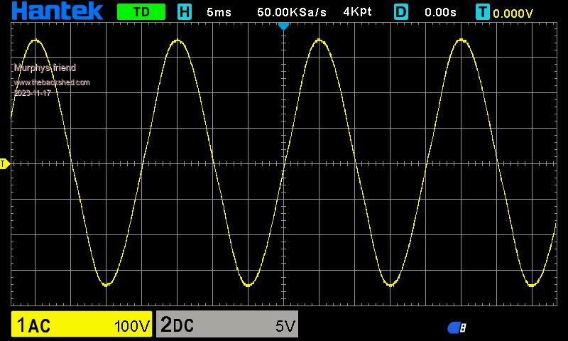
The AC waveforms are good, this is what 150W load looks like:
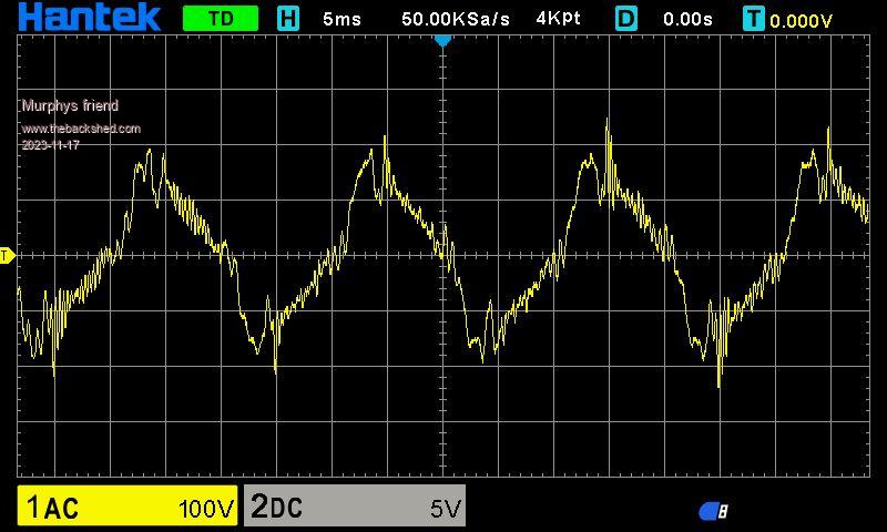
And this trace at 1100W load:
I then subjected this inverter to my chop saw test, this is rather severe for such a small transformer but everything survived the test multiple times.
The start up wave form looks horrible but it *did* start up every time :
Once it was up to speed (but not cutting anything) I got this wave form:
I'm looking forward to your comments and will continue later to post some pictures of my new (downsized) caravan inverter.
Murphy's friend Guru Joined: 04/10/2019 Location: AustraliaPosts: 583
Posted: 08:19am 17 Nov 2023
Copy link to clipboard
Print this post
It looks like the last picture upload did malfunction, here is that picture:
Revlac Guru Joined: 31/12/2016 Location: AustraliaPosts: 961
Posted: 09:50am 17 Nov 2023
Copy link to clipboard
Print this post
Can you check the 12V out of the little transformer, to see if there is any deviation in voltage? might be hard to see, or its something else. Cheers Aaron Off The Grid
Murphy's friend Guru Joined: 04/10/2019 Location: AustraliaPosts: 583
Posted: 10:10am 17 Nov 2023
Copy link to clipboard
Print this post
Thanks Aaron. When the main AC voltage goes up then, naturally, the little sensing transformer primary voltage also goes up. This then proportionally will change the secondary (sensing) voltage.
What there appears to be is some positive feedback but I cannot imagine how.
The strange thing is when I ran the chop saw the AC voltage did not increase, at least I did not notice any.
I might try to cut some steel and see if the inverter voltage regulation works better with an inductive load.
Its not something I will panic about, just being curious. Big loads in the van will be short microwave loads and the occasional A/C startup & run.
Revlac Guru Joined: 31/12/2016 Location: AustraliaPosts: 961
Posted: 06:29am 18 Nov 2023
Copy link to clipboard
Print this post
I just had a look through some old photos and I did see an increase in voltage from 230vac to 235vac, this was running a kettle, at the time I had a cheap little scope on the 12v transformer, there was a small increase in voltage 17.44 to 17.64 peak voltage on the DSO, its a very small amount and hardly worth looking at. I thought that if there is some unfiltered noise coming through the transformer and the small peak voltage is lost in the resistor rectifier stage before the VFB input, its just a theory and would need to check it against other types of loads, but if its not a problem.... It might be my chokes are not quite right. Hey my kettle will boil faster, then when done the inverter will lower the output voltage, power save mode Cheers Aaron Off The Grid
Murphy's friend Guru Joined: 04/10/2019 Location: AustraliaPosts: 583
Posted: 07:35am 18 Nov 2023
Copy link to clipboard
Print this post
I placed this inverter in my caravan and had it power the Aircon. AC voltage increased from 230V to 240V with the compressor running but, as you say, it goes back to 230 with just the A/C fan running. That's good enough for me.
I just love this LF inverter, this little 1KW unit will start & run the caravan A/c while the 2KW HF inverter will not start it .
Murphy's friend Guru Joined: 04/10/2019 Location: AustraliaPosts: 583
Posted: 08:22am 18 Nov 2023
Copy link to clipboard
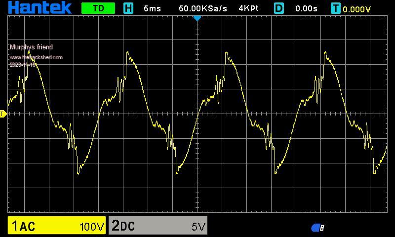
Print this post
Here is what my caravan aircon does to the inverter output.
First the startup wave form:
And when its running:
Murphy's friend Guru Joined: 04/10/2019 Location: AustraliaPosts: 583
Posted: 08:37am 18 Nov 2023
Copy link to clipboard
Print this post
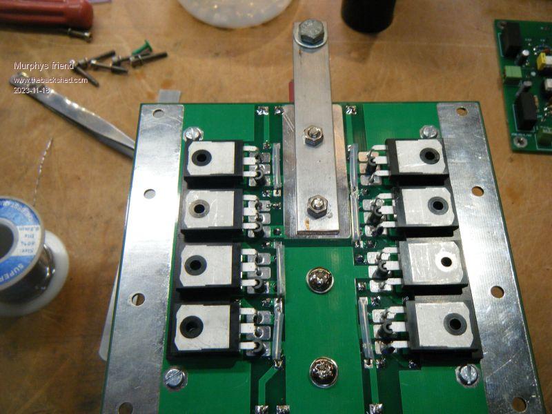
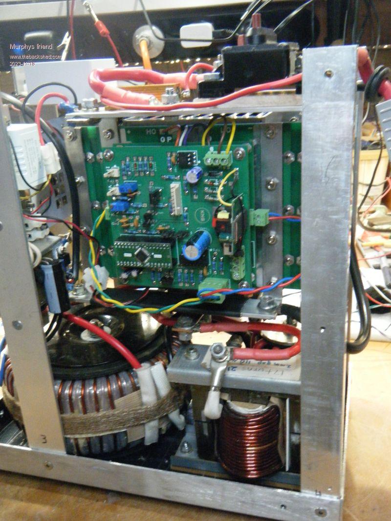
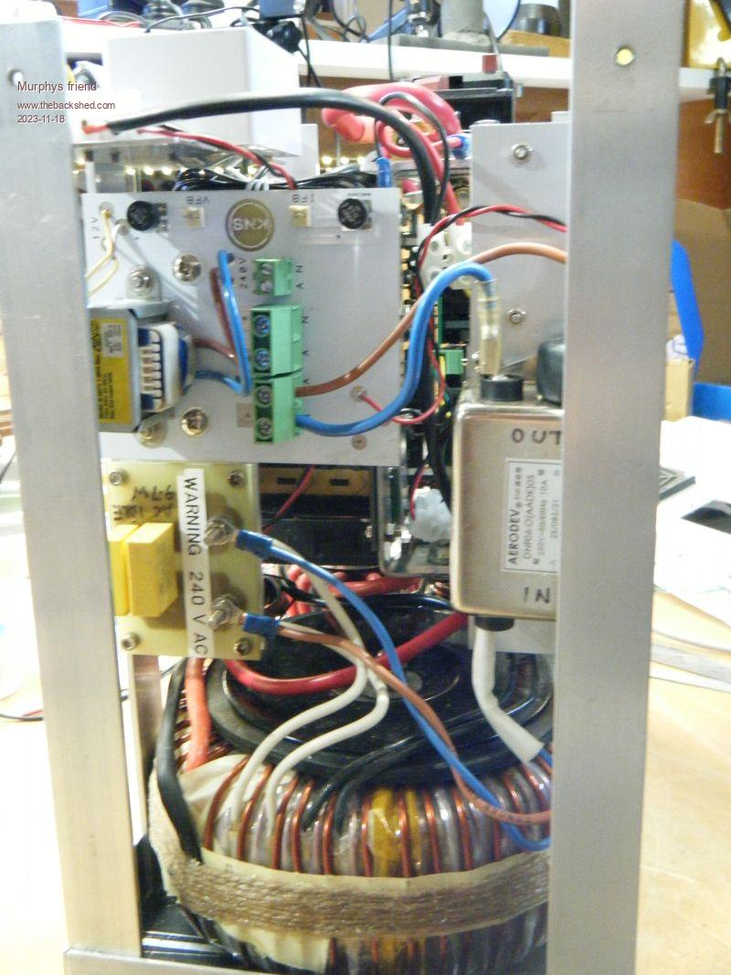
Now a few pictures, I have completely re built what is shown at the beginning of this thread. The idea was to have a smaller, lighter LF inverter for my van. The one I built some time ago works fine but due to its size and weight it was very difficult to insert/ extract from its tunnel boot home.
This is the power board underside, showing the 8 mosfets with ferrite beads on each leg that connects to the primary:
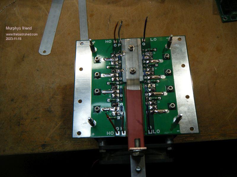
The top side of the power board:
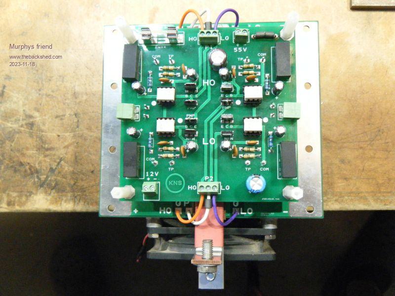
And the driver board piggy back on top:
Then the control board piggy back on the lot:
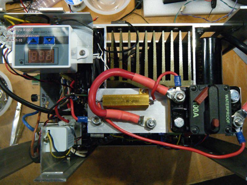
Now a few pics of the build:
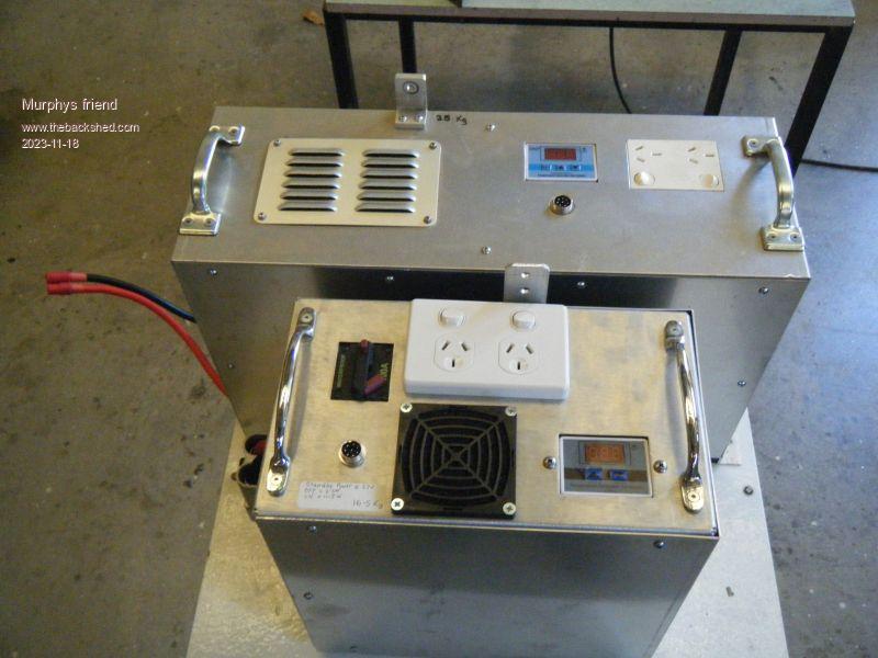
And the size difference of the old inverter behind the new inverter. The weight difference is 25kg reduced to 16.5kg:


 .
.

.jpg)
.jpg)


 .
.