Notice. New forum software under development. It's going to miss a few functions and look a bit ugly for a while, but I'm working on it full time now as the old forum was too unstable. Couple days, all good. If you notice any issues, please contact me.
Murphy's friend Guru Joined: 04/10/2019 Location: AustraliaPosts: 583
Posted: 09:15am 19 Nov 2023
Copy link to clipboard
Print this post
I have not measured it with the new, smaller, inverter but with the old 1.5KW one (shown behind the new one in the pic) the startup current was nudging 700Amps. This is from a 24V, 120Ah lithium battery with a 250Farad capacitor assistance.
analog8484 Regular Member Joined: 11/11/2021 Location: United StatesPosts: 89
Posted: 07:07pm 19 Nov 2023
Copy link to clipboard
Print this post
For clarification, with the old 1.5kW inverter, the aircon was drawing ~700A@24V from a 120Ah battery with 250F (super?)capacitor and could not start? From the numbers it looks like the aircon startup surge is more than 10x the nominal inverter power capacity?
Now the new 1kW inverter starts the aircon with no issue, apparently with an even higher surge to nominal power capacity ratio (looks like 15x+). If so, it's quite remarkable and frankly a bit hard to believe. What do you attribute the better performance to?
Murphy's friend Guru Joined: 04/10/2019 Location: AustraliaPosts: 583
Posted: 07:36am 20 Nov 2023
Copy link to clipboard
Print this post
You are right, its hard to believe. So hard that I did not believe it myself , thinking about it. What happened is a scaling error when reading the data, sorry about that. I suppose at 77 years the brain is not as sharp as it once was.
BTW, the old 1.5KW LF inverter *did* start & run the A/C. It was the original 2KW HF inverter that could not do it and made me tinker with LF inverters for that job. The 250F ultra capacitor was another idea to get it running with the HF inverter - it was not enough grunt - but I left it in place. I hope that clears any confusion.
Anyway, I re measured the startup current today and it's about half of what I quoted above .
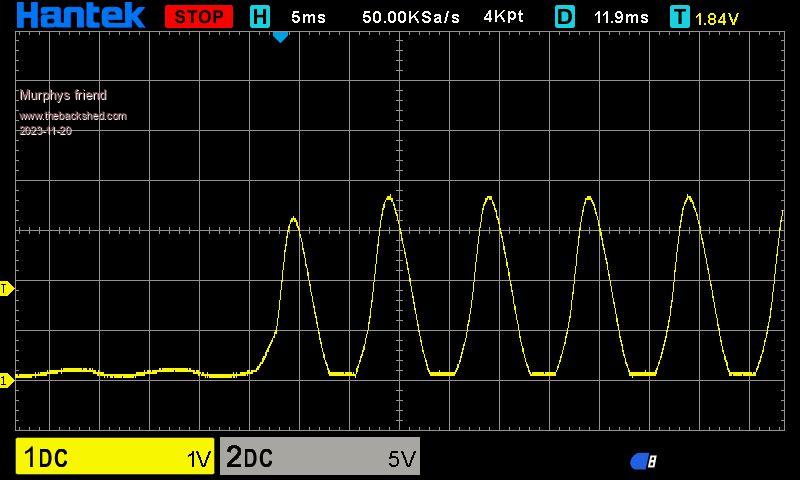
I used a 400A Hall sensor at the positive power lead to the inverter. On the picture below each vertical division represents 100A of current.
Why there are several current peaks I have not yet figured out - suggestions? -, the air conditioner starts up with the fan running only for a while before the compressor kicks in. The trace was triggered by the compressor startup.
phil99 Guru Joined: 11/02/2018 Location: AustraliaPosts: 1783
Posted: 11:25am 20 Nov 2023
Copy link to clipboard
Print this post
If the peaks you mention are the ones in the trace above, they are just a reflection of the AC output current. On the DC side you get one per half cycle. The time scale is 5mS/Div. so the peaks are at 10mS intervals, exactly what they should be for 50Hz output. Edited 2023-11-20 21:26 by phil99
analog8484 Regular Member Joined: 11/11/2021 Location: United StatesPosts: 89
Posted: 05:07pm 20 Nov 2023
Copy link to clipboard
Print this post
Thanks for the quick update. 400A is still well above the typical 3:1 surge expected of LF inverters and very impressive. The 250F caps must really help quite a bit.
Revlac Guru Joined: 31/12/2016 Location: AustraliaPosts: 961
Posted: 10:56pm 20 Nov 2023
Copy link to clipboard
Print this post
Interesting, I run 2 500w aircons they start ok and locked rotor is still easy enough to handle, locked rotor on the fridge is a little over 2000w for about 5+ seconds, will soon be switching the house over to the LF inverter, Just thinking I would not see those high current peaks with the 5Kw HF Inverter, would that be right?Cheers Aaron Off The Grid
KeepIS Guru Joined: 13/10/2014 Location: AustraliaPosts: 1358
Posted: 11:20pm 20 Nov 2023
Copy link to clipboard
Print this post
Hi Klau,
As Phil said, you are seeing a 100Hz DC current waveform from the generation of each half cycle of the 50Hz AC waveform. I refer to them as instantaneous peak DC input current excursions.
These are PEAK current pulses and should not be confused with the Actual ratio of AC surge input current to running AC current of the AirCon.
These Peak swings will always be there even when idling, but obviously at a very low level. Obviously the DC current waveform (peaks) will be high until the AirCon had settled down.
One nice thing about using an "Inverter" Aircon is the linear rise and fall in power, no sudden shock to the 1kW Inverter from compressor switching surges.
Love the project, another on my to-do list.It's all too hard. Mike.
KeepIS Guru Joined: 13/10/2014 Location: AustraliaPosts: 1358
Posted: 11:31pm 20 Nov 2023
Copy link to clipboard
Print this post
When I was running the HF inverter there was the same or higher input Peak waveforms, the HF inverter was running at 24V, so more current, my LF system is now 48V.
If you average those peak waveforms out it comes down to something you can get your head around, but this is still a rough "indication" of the instantaneous peak currents that the inverter bridge FETS are dealing with. .It's all too hard. Mike.
Revlac Guru Joined: 31/12/2016 Location: AustraliaPosts: 961
Posted: 12:02am 21 Nov 2023
Copy link to clipboard
Print this post
Ok that sounds fair enough, I just got tricked up because the converter stage on this HF is about 26Khz, but yes it should average out. Cheers Aaron Off The Grid
Murphy's friend Guru Joined: 04/10/2019 Location: AustraliaPosts: 583
Posted: 09:23am 24 Nov 2023
Copy link to clipboard
Print this post
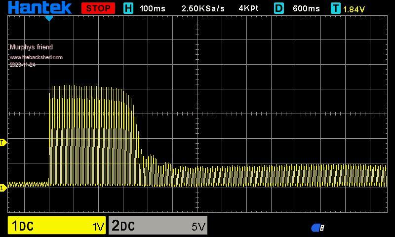
Now that I know what these peak current pulses represent, I was curious how long they persisted. Here is a screenshot of the full startup cycle:
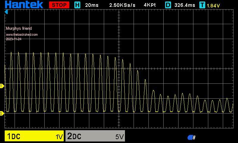
We can see the 400amp peaks persist for about 300 ms before the current settles to the run value. Here is an expanded view of the tail end of the trace:
It shows the run peaks to be around 100Amp which translates to a 40-45A continuous current on my clamp meter.
I had fitted two chokes in this inverter, one being a gapped C core silicon steel type and the other a triple Sendust ring core type. While their saturation point is above the run current peaks this is not the case for the startup peaks. This appears to be fine with my inverter design , time will tell...
The 120Ah battery bank was continuously charged from an MPPT charger during the testing.
I wanted to know how hot the heatsink in my inverter got with the aircon trying to cool down a hot (ambient was 35 deg. C) caravan. Too hot as it turned out, the heatsink temperature kept on climbing and I turned the experiment off when it passed 70 deg. C. The internal inverter fan is mounted directly under the heat sink, coming on at 50 deg. C, and this 80mm fan was not up to the job .
So I fitted another 80mm fan at the air outlet vent on top to extract the air and also made another air inlet at the transformer end of the inverter.
When testing today (another 35 deg. ambient) this did the trick (just ), the heatsink temperature stayed below 52 degrees initially and then cycled between the temperature controller settings of 50- on, 45- off once the internal van temperature settled to the aircon setting.
What I learned from this is that a caravan can be a very hostile environment for an inverter. My 17'6" offroad single axle caravan is 11 years old and not of the fully insulated build the newer vans are nowadays.
The batteries, most of the electrics/ electronics and the inverter are located in a front tunnel booth. Access is via a front hatch, making it difficult to get at things in there, besides, being made from chequer plate aluminium, getting really hot when parked in the sun.
I hope this info may help anybody considering fitting a home made inverter to their caravan.
analog8484 Regular Member Joined: 11/11/2021 Location: United StatesPosts: 89
Posted: 07:22pm 25 Nov 2023
Copy link to clipboard
Print this post
It's nice to see how clean the waveforms are in terms of high frequency components. The chokes and caps look to be working well. Can you share info on the ultracaps you are using? Are they Maxwell?
Revlac Guru Joined: 31/12/2016 Location: AustraliaPosts: 961
Posted: 12:06am 26 Nov 2023
Copy link to clipboard
Print this post
Thats good Murph, as long as those batteries don't get too hot, I have mine outside, the thermal mass of all the batteries together keeps them cooler than the ambient temp, so long as there isn't several really hot days in a row. Cheers Aaron Off The Grid
Murphy's friend Guru Joined: 04/10/2019 Location: AustraliaPosts: 583
Posted: 08:35am 26 Nov 2023
Copy link to clipboard
Print this post
Thank you, I bought those ultracaps years ago from an US ebay seller who apparently got them from buses where they were used. They seem to last forever;-)
I think they are maxwell (cannot see them now - built into a box). They are 3000F / 2,7V each, I have 12 in series. From memory they are about 2" diameter and 6" long with an aluminium screw stud at each end for connection. I balance them with red LED's & resistor across each, otherwise the individual voltage may drift out of spec.
Murphy's friend Guru Joined: 04/10/2019 Location: AustraliaPosts: 583
Posted: 08:41am 26 Nov 2023
Copy link to clipboard
Print this post
Unfortunately there is nothing I can do about the battery location, The are in the same place as the original flooded LA batteries. I did fit two computer type exhaust fans and one at the opposite end to blow outside air in. The van is parked in the sun and does get hot in that tunnel booth. Opening the front hatch helps which I have been doing in the heat wave we have here in Perth presently.


 , thinking about it.
 .
.


 , time will tell...