Notice. New forum software under development. It's going to miss a few functions and look a bit ugly for a while, but I'm working on it full time now as the old forum was too unstable. Couple days, all good. If you notice any issues, please contact me.
Murphy's friend Guru Joined: 04/10/2019 Location: AustraliaPosts: 583
Posted: 08:17am 07 Oct 2023
Copy link to clipboard
Print this post
Its interesting to see the different saturation curves of the chokes I have here (quite a few )
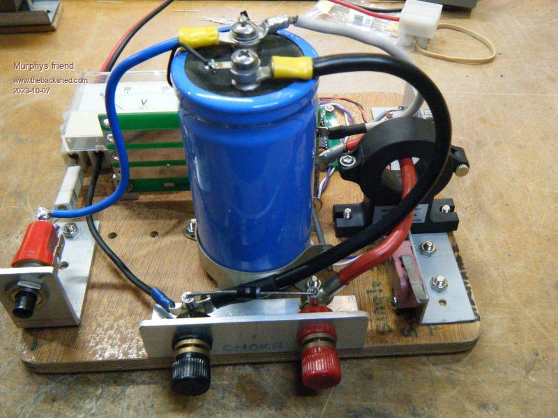
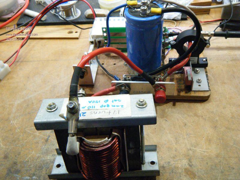
For that I made a tester which looks like this:
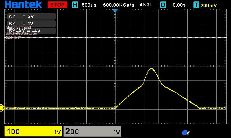
First I tested how the capacitor dumping its full charge into a short circuit looks. I had to charge it only up to 10V or the trace would shoot off the top of the screen.
The yellow trace represents the current sensed by the Hall sensor. One vertical screen division equals 100Amp. This applies to all the following traces.
Next I tested a toroidal choke with 12 turns. The capacitor charge was charged to 30V, as it was for all the following tests. That choke measured 90uH on my FNIRSi DSO-TC3 tester.
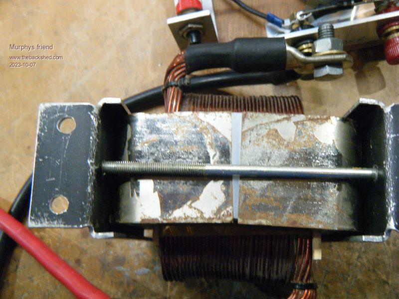
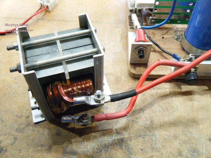
Then I tried a silicon steel E core, 17 turn, 110uH
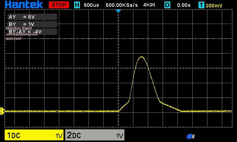
Followed by another toroidal choke. 10 turn, 3 ring Sendust material, 40uH
Another silicon steel choke, this one a C core with a 'swinging' gap. 12 turn, 40uH
Lastly a dual ferrite E core choke, like we used at the beginning of inverter building. 20 turn, 6mm gap, 130uH.
.
If anybody is interested in doing similar tests I can post the simple schematic for the tester. The inexpensive FNIRS DSO mentioned above has a single shot capture feature and works - trigger setting is a bit tricky and the traces are on a much smaller screen as shown here. There are 3 spare PCB's (includes peak test PCB as described in another post here) available for the price of posting.
Murphy's friend Guru Joined: 04/10/2019 Location: AustraliaPosts: 583
Posted: 08:26am 07 Oct 2023
Copy link to clipboard
Print this post
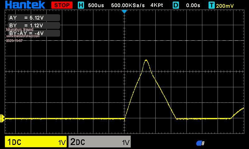
Ooops, it looks like I confused some pictures, unfortunately the editing feature does not work for me.
So, the trace shown after the 17 turn silicon steel choke belongs to the 12 turn toroidal choke.
The trace for the 17 turn choke looks like this:
Revlac Guru Joined: 31/12/2016 Location: AustraliaPosts: 961
Posted: 09:09am 08 Oct 2023
Copy link to clipboard
Print this post
Nice tidy looking build. I have a few of those type of capacitors, what size is that one? 59000ufCheers Aaron Off The Grid
Murphy's friend Guru Joined: 04/10/2019 Location: AustraliaPosts: 583
Posted: 10:07am 08 Oct 2023
Copy link to clipboard
Print this post
Thanks Aaron. The capacitor is 7500uF/75V, ex old fashioned power supply - found it in my parts box. Do not use too big a cap, I tried initially 2 x 10000uF and had to use a very low charge voltage or the trace shot off the screen. The mosfets I used can handle about 1000A peak, the biggest peak in the pics is about 750A.
Initially I used 2 x HY4008's, they did not last long. it would require 4 in parallel if that type is chosen.
rogerdw Guru Joined: 22/10/2019 Location: AustraliaPosts: 795
Posted: 10:25pm 12 Dec 2023
Copy link to clipboard
Print this post
Hi Klaus, since I've been looking at winding some chokes for my MPPT I've been trying to make sense of all this info ... but am a little lost as to what I'm looking at.
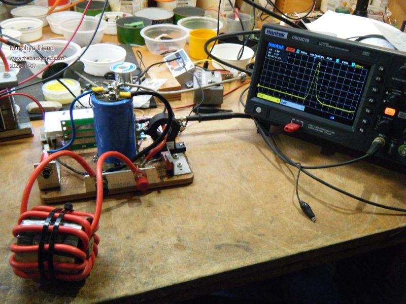
So to set me straight ... you've built a system where you charge a cap up to 30V and then dump it into your test choke.
The discharge lead feeds through a current sense coil so you can monitor the waveform on your DSO.
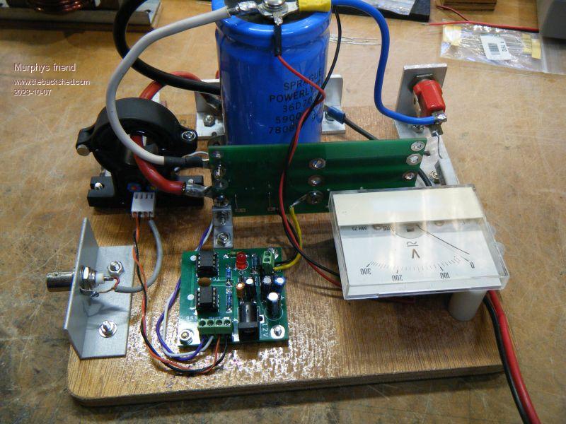
What does the analogue meter read? I see it has a 300V FSD. Is that just to show what you've charged your cap up to ... or is it somehow used as an analogue ammeter? Peak test pcb?
Then my main questions ... what are you actually looking for? What makes one choke better than another? ... and I assume that also depends on the application? Thanks.Cheers, Roger
Murphy's friend Guru Joined: 04/10/2019 Location: AustraliaPosts: 583
Posted: 02:09am 13 Dec 2023
Copy link to clipboard
Print this post
Hi Roger, That analog meter is something I found in my parts box. I removed its serial resistor and the FSD is about 60V now. The meter is just there to see how far and when the capacitor is charged, you could easily use a multimeter instead.
I am looking at the up slope of the trace. You can see above that with silicon steel cores (as you have) the slope ramps up to a point and then takes off almost vertically. That is the point at which core saturation occur. You want your peak inverter currents below that point since the choke no longer does its job beyond that point.
With the Sendust ring core chokes the trace is very different, it ramps up in an exponential fashion. This tells me saturation is more gradually rather than sudden as in the silicon steel cores. Picking a saturation point with the sendust core chokes is not exact, I chose a point where the trace slope roughly matched the silicon steel choke before saturation.
For an inverter I do not want the choke to saturate at the expected current, I suppose the same applies to the MPPT choke.
I find that ferrite E cores saturate at a much lower current than similar sized silicon steel cores, for that reason I do not use them in my inverters.
You are right, the saturation part depends on the application.
If you, or anybody else, is planning to build the above tester keep in mind the very high peak currents involved (hundreds of Amps) and choose the parts accordingly.
The trigger switch is tricky, it needs de bouncing as the mosfet can switch very rapidly. Even so, I found a micro switch with a long lever arm best for an instant trigger as this needs to be done right after the cap is fully charged.
BTW, the above traces were among the first I took with my new DSO so keep in mind that the time scale could be shown better. It's a great piece of gear but does require a longish learning curve .
rogerdw Guru Joined: 22/10/2019 Location: AustraliaPosts: 795
Posted: 03:10am 13 Dec 2023
Copy link to clipboard
Print this post
Thanks Klaus, that was very helpful ... and I did wonder if you had modded the meter to bring it to a suitable range.
When you said the time scale could have been shown better, I assume you would widen it out so you can hopefully see the change in direction/saturation point more clearly.
I've had a DSO for years but probably only use it at 10% of its capability. Keep promising myself to explore it some more and get better value from it.Cheers, Roger
Murphy's friend Guru Joined: 04/10/2019 Location: AustraliaPosts: 583
Posted: 07:42am 13 Dec 2023
Copy link to clipboard
Print this post
You are assuming correctly.
The price of DSO's these days had me convinced that my 40yo CRO is overdue for retirement. I still use it to monitor the sine wave from my inverters, at 35MHz bandwidth it does not show the noise spikes that become visible on the DSO .
I particularly like the trace to USB stick capture feature of the DSO, very handy for forum posts.


 )
)


 .
.