
|
|
Forum Index : Electronics : Inverter DC side current
| Page 1 of 2 |
|||||
| Author | Message | ||||
| JohnTaves Newbie Joined: 01/11/2023 Location: United StatesPosts: 19 |
Should the DC side current of an inverter be relatively stable, I mean not oscillating at a high frequency from 0 to 2x the load? I have an Ampinvt 6kw 24V split phase inverter (Chinese made off-the shelf). It worked fine for several weeks where the DC amps seemed relatively stable. Now, it seems to work fine, but the DC amps are oscillating. My BMS updates the display every 2s, and the DC amps are jumping around from negative to 2x the expected amount. For example, if I am running some AC load that uses 1500W, I expect to see something like 60a on the DC side. Instead it is jumping from zero to 140a. I put a digital shunt inline on the positive DC lead and took samples at 4.87ms. I grabbed 2k samples and plopped them into a discreet fourier thing and it had a big spike at 34 samples, which translates to .166ms (6hz). Ampinvt is trying to tell me that this is normal. The Ampinvt support has near zero credibility with me because of their stupid and changing answers on other questions. I suspect that the non-engineer person handling the support emails, asked the engineer if it was normal for the DC amps to vary, and he said yes, thus failing to ask if it was OK for the DC amps to oscillate from 0 to 2x of the load at high frequency. Shouldn't there be some sort of capacitance on the input side to smooth this out? I would have expected that some types of batteries might not be able to keep up with those current swings and thus a capacitor would be necessary to maintain the input voltage/current. Isn't this the capacitance that provides the inrush of current when you attach the DC side? When I open up the unit to look for bloated or otherwise damaged capacitors, I assume I am going to find a set of big ones on the input side, right? Do you have any ideas why I am seeing 6hz base frequency (not important)? Thanks for any help you can provide. |
||||
| phil99 Guru Joined: 11/02/2018 Location: AustraliaPosts: 1783 |
The 6Hz value might be an alias of the real frequency of 120Hz (assuming your inverter is 60Hz) caused an interaction between it and your sample interval. Try 4.1667mS if possible (2 samples per 120Hz cycle or other exact multiple). If you look at the home brew inverters on this forum they usually have massive banks of capacitors on the DC supply close to the output devices for exactly the reason you describe. They also use short and fat battery cables. Measuring the current between the battery and the caps. should then look better. Edited 2023-11-01 15:15 by phil99 |
||||
| JohnTaves Newbie Joined: 01/11/2023 Location: United StatesPosts: 19 |
Thanks for your response! I posted my question in 3 different places and nobody answered my question. I thought it was an obvious "Yes, the DC current should not oscillate at a high frequency". I was starting to seriously doubt my head was screwed on tight. I'll take this thing apart and hopefully I will find a visibly damaged capacitor so I can photo it and get Ampinvt to pay attention. I bought it because it was cheap and has a big round transformer. I am tempted to build my own because none of the off-the-shelf products are both low frequency and have a simple on/off switch for both charging and inverting. I have a custom BMS for my RV that does not have a way to shut off current to the battery. Instead it turns on/off the loads and PV as necessary to not over charge, or drain the batteries. I have not found a relatively easy to follow recipe on this forum to build a 6kW split phase 24v 60hz inverter, where they tell me what transformer to buy and provide the pcb designs. They all seem to say that you find some junk transformer and rebuild it. Am I missing something? Anyway, thanks for answering my question. |
||||
| wiseguy Guru Joined: 21/06/2018 Location: AustraliaPosts: 995 |
It is unlikely that you will find any 6kW 60Hz split phase transformer design here as we are predominantly 240V 50Hz. That being said both the EG8010 and Nano controllers can be easily configured for 60Hz. There is not a simple cookie cutter design - as yet but it is coming we are almost there. As there are many solar grid feed inverters being junked it is relatively easy to find a transformer that has a pre-wound (in our case 230/240V) winding that saves a lot of work and you simply have to add a winding to suit the nominal battery voltage of the inverters supply. There are a lot of influencers/influences in the designs on here such as 12/24/48, lead acid versus lipo, back charging capable, 50/60 Hz, total power output etc. That is why a simple overall design that will suit everyone is difficult to achieve In my recent posts there is a method to reduce the drive winding by half the turns to drive two "stacked" toroids where the secondaries could be paralleled for extra power or the outputs could be put in series or just have two isolated outputs. Can I assume that a split phase means that the phases are in sync and it will be two 110/120? in series so that there would be 220/240 across the total. Why is this necessary if this is the case, is there a 220/240 load you want to use ? Or does it mean the 110/120V is split in half as 2 x 55/60V windings in series ? Depending on your answer/s to this it may be possible to order and buy a prewound Toroid for your purposes so no self winding is necessary but it will not be cheap. Edited 2023-11-02 07:51 by wiseguy If at first you dont succeed, I suggest you avoid sky diving.... Cheers Mike |
||||
| JohnTaves Newbie Joined: 01/11/2023 Location: United StatesPosts: 19 |
Thanks a ton for your responses. I don't need 240V. I say split phase because the off the shelf units tend to have the 240V with 2 hot 120V legs when the inverter is above 5kw. I assume they do this because it is handy to have 2 legs that are half the max amps so that you can run the inverter output into the panel with common 12-14 gauge wire. The panels (I am in the USA) generally have the two circuits on even/odd circuit breakers. |
||||
| rogerdw Guru Joined: 22/10/2019 Location: AustraliaPosts: 795 |
I know many wind their own transformers or modify existing windings, but I have seen toroids available from aliexpress ... examples Example 2 Example 3 Of course with their weight, freight is a huge expense. Cheers, Roger |
||||
| JohnTaves Newbie Joined: 01/11/2023 Location: United StatesPosts: 19 |
Thanks, for the info. If I don't succeed in getting this Ampinvt fixed, it has a huge transformer and a nice enclosure that will do the job. The improvement I would make by creating my own (beside working properly), is to have 2 simple open/close connectors. One will be to shut off the charging and the other to shut off the inverter. If the circuit is open, it won't charge. If the other circuit is open, the inverter is off. I would not have any UI on the inverter. Background: I have a home made BMS for my LiFePo4 battery. It has a bunch of SSRs that allow me to control turning on/off all loads (the inverter and the DC/DC converter) and all chargers (solar and mains). I also use it to control the furnace that will keep the batteries and water from freezing, and maintain the temp in the RV. (just to pat myself on the back, the cell monitors are wireless. They deliver the Volts and cell temp via bluetooth) Unfortunately, the Ampinvt is like all off-the-shelf inverters, where they have logic to control charging and shut off when the battery gets too low. That logic is pointless because it looks at whole pack voltage, and they do not have a simple open/close circuit to turn it on/off. Basically it is a relic from the lead-acid world. Indeed the solar controllers suffer the same problem. They are all suboptimal for lithium because they all use whole pack voltage to made charge/load decisions. My solution for the Ampinvt is to put an SSR on the mains input to be able to shut off charging. I can also program my BMS to short the momentary on/off switch to shut it down to eliminate its load. I can also monitor a 5V signal from the inverter to ensure it did go off. However, that logic requires a functioning BMS. If my BMS crashes I want all control circuits to open and thus everything shuts off (Although, the BMS has an uptime of over 1 year without any glitch at all). |
||||
| JohnTaves Newbie Joined: 01/11/2023 Location: United StatesPosts: 19 |
I opened up the inverter. The capacitors look ok physically. The inverter also maintained 25V after I disconnected power. However, normally my resistor gets very hot when I use it to drain or charge the capacitors. This time I was able to hold the resistor without having to disconnect every second to let it cool. I attempted to measure the capacitance and got a 0 reading when I used my cheap multimeter across the battery inputs. Maybe I need to disconnect things before attempting to check the capacitors? Maybe my multimeter is not capable of measuring large values? I tried it on a small cap I had lying around and it produced the correct value. Is it possible that the capacitors are OK and something else failed to cause the DC current to oscillate at 60hz? My problem is that the DC amps are oscillating from 0 to 2x the expected current when the inverter is on and either charging or inverting regardless of the load. I uploaded a photo of the only components that look discolored on the control board. I included photos of the capacitors and the fets in the hopes that someone might tell me if these are decent quality or not. 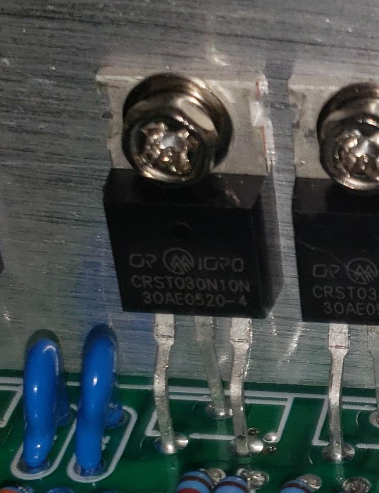 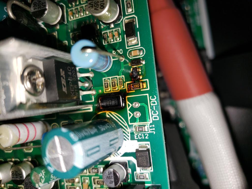 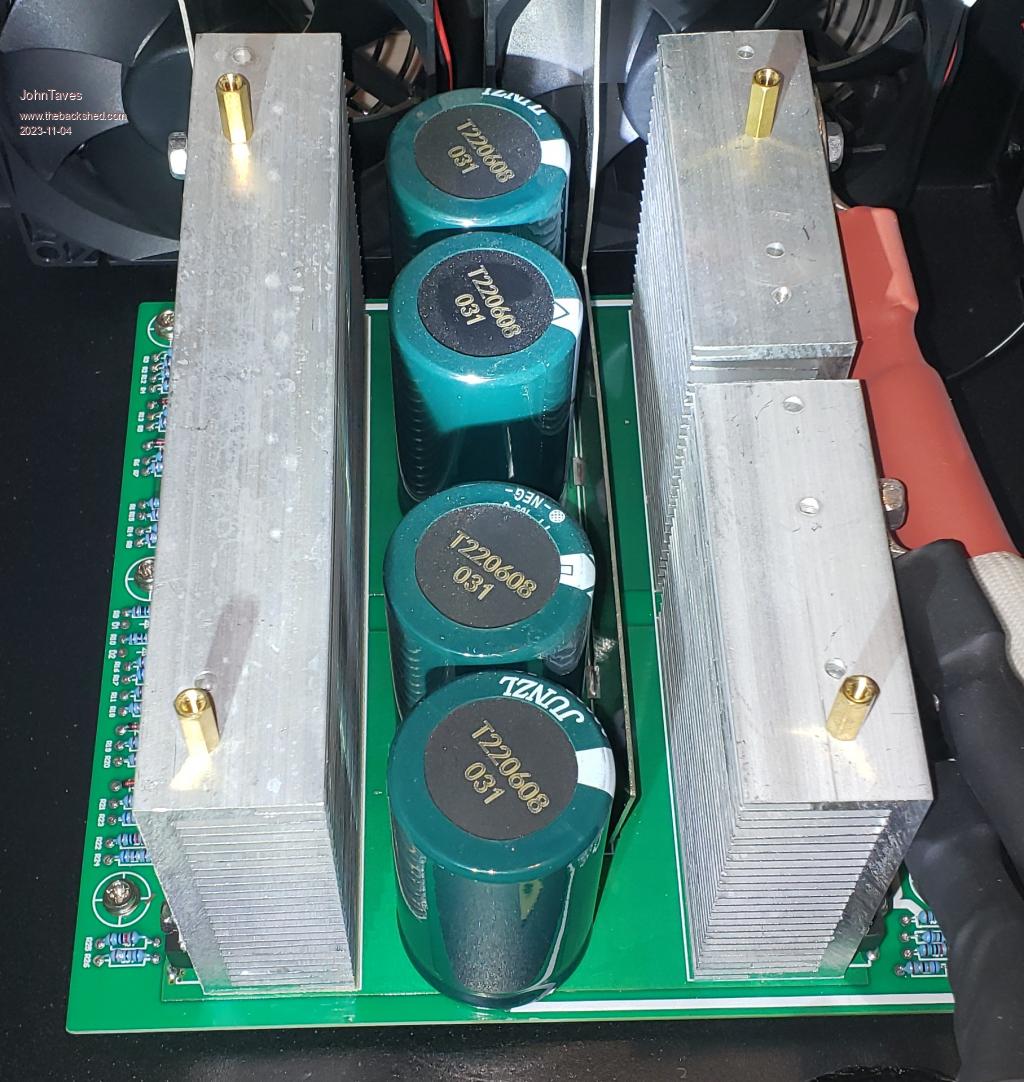 |
||||
| nickskethisniks Guru Joined: 17/10/2017 Location: BelgiumPosts: 411 |
If you would visualise the dc input current with an oscilloscope, you see (in theory) a sinewave with 100 or 120Hz frequency. Varying between zero and 1.41*Irms, no negative current. The capacitors will filter pretty good the hf switching but not the fundamental frequency. More capacitance will make your voltage ripple smaller but you also need an inductor to lower the current ripple. 0.166ms is more like 6kHz, not 6Hz? You have a scope? What kind of load are you using? You can test your capacitors with an oscilloscope/ multimeter+stopwatch and a high resistance to find out the capacitance by discharging it. |
||||
| Godoh Guru Joined: 26/09/2020 Location: AustraliaPosts: 378 |
John it may be a trick of the light but in your second photo there looks like heat related damage to some components just above where it says DC-DC. one component looks like a mosfet driver transistor the other one has something like 101 written on it. I would suggest looking carefully there for damaged components Pete |
||||
| wiseguy Guru Joined: 21/06/2018 Location: AustraliaPosts: 995 |
Good pictures, re the quality of capacitors and FETs, it's not possible to know as forgeries are so good these days. But the main capacitors show no typical signs of degradation and the main FETs don't look stressed either. The "discoloured" parts on the control board appear to be the real problem, I am confident there is more going on there than just discolouration - I would expect that some of those bits (and maybe others that may or may not be so obvious) need replacing as they are now faulty/broken. Good luck in your endeavours to fix it, finding a schematic will probably be the hardest part, finding another unit and reading off the parts might be easiest or and reverse engineering the schematic to help understand why it failed and what else may be faulty! Posting some details of your wireless BMS would no doubt be interesting as BMS systems are currently quite topical here. Edit: Godoh posted whilst I was creating my post with similar concerns. Edited 2023-11-04 09:36 by wiseguy If at first you dont succeed, I suggest you avoid sky diving.... Cheers Mike |
||||
| phil99 Guru Joined: 11/02/2018 Location: AustraliaPosts: 1783 |
A picture is worth a thousand words so Ampinvt won't be able to dismiss you again if you email the photo of the burnt bits to Ampinvt Tech. Support and request a circuit diagram and any other relevant servicing info they may have. Even if they regard the complete circuit as proprietary IP a reputable company would provide enough information to repair it. If it is still in warranty get them to repair / replace it. |
||||
| JohnTaves Newbie Joined: 01/11/2023 Location: United StatesPosts: 19 |
I am pretty sure the 6Hz results from the measurement. I sampled the amps at 4.87ms per sample, then threw 2000 samples into a discrete fourier and got a huge hit at 34 samples which resulted in .1666 seconds. This was proof to me that there was not some other random problem separate from the inverter. The main point is that it is oscillating from zero amps to 2x the expected load. So, if I have 3kw of load on the AC side, the 24VDC amps should be around 150, but they are oscillating from 0amps to over 300amps. I have no problem expecting to find ripple current at the 60hz (or rather 6hz if I sample at 4.87), but only if that current was a ripple and not a freaking tsunami. Thanks to the phil99, wiseguy, and Godoh for commenting on the bad parts. I have emailed that back to Ampinvt support. Just FYI: The Ampinvt support is absolutely dreadful. I do not know how they operate, but if you took 10 people that know nothing about inverters and had them randomly pick emails to answer, and reply after reading only a few random words of each email, you'd do no worse than the Ampinvt support. The last email from them indicates that they will send a replacement board, but they also suggested I replace the battery and that the oven might be faulty!. I was tempted to explain that the battery is keeping up with the demands of the inverter by delivering 0 to 300amps at 60hz which proves that it is in good shape. |
||||
| phil99 Guru Joined: 11/02/2018 Location: AustraliaPosts: 1783 |
Getting a replacement board is ideal. Comparing the two will simplify repair and then you have a spare for next time! Your sampling interval is too low and could produce a false artefact. The DC ripple peaks will occur for each half cycle of the output so it will be 120Hz. 120Hz has a period of 8.333mS. Your sampling rate is less than two per cycle and will create a low frequency beat or alias signal. You need to sample at an integer fraction of 8.333mS to get a stable reading. The more samples per cycle the better the accuracy. A 0.8333mS interval would give very good results. |
||||
| rustyrotors Newbie Joined: 07/01/2023 Location: United StatesPosts: 31 |
if you have a power supply, you could set current limiter and measure how long the inverter takes get up to voltage, compare with cap values to see if they match. i wonder if the fets or the gate drive power supply is damaged, causing slow turn-on time and a bit of shoot through. what are the current peaks at idle, or is it always 2x no matter the draw. i think the battery current waveform should theoretically be a rectified sinewave with a peak of Irms * sqrt(2)? so 84A at 60A load, but will be higher than that if the choke is inadequate. i bought that same inverter, but have not used it yet. i figured if it blew up i would replace the guts with those egs002 chinese inverter boards you find on ebay or aliexpress. i know people have had mixed results on here, but i have found the chinese boards very reliable if you disable overcurrent protection on the egs002 (remove U4 and short C19, C24). its interesting the egs002 will still shutdown into a short, depending on how lossy your transformer is, due to voltage drop at the Vfb pin. Also replace the power caps with the biggest caps you can fit between the heatsinks Edited 2023-11-06 04:22 by rustyrotors |
||||
| JohnTaves Newbie Joined: 01/11/2023 Location: United StatesPosts: 19 |
I figure the loose board in the photo below is called the control board, and the one with the fets, caps, and heatsink is the power board. The control board has the failed components and Ampinvt has seen the image of that, and immediately asked for my address and sales info. They are sending something to fix this. I am not sure what they are sending. (I assume it will be the control board. But if I wasn't eager to open this and find bad parts, I don't think I would have managed to convince them it was bad. But if they had comprehended what I was saying about the DC current, what were they going to do? Would I have to ship this heavy thing back for them to fix? Because I opened it, are they now OK sending me the board to replace? I am just thinking out loud.) Anyway, back to my real question. I see two different types of chinese inverter boards. One has no power components, so I figure it is the egs002 based control board. The other solutions have the heatsinks, fets, and caps, and also that egs002 control board sticking up. Are you saying you'd swap out both the control and the power boards (I apologize if I am not using the correct name for these two)? Or maybe just the control? I really want to be able to turn this thing on/off by opening/shorting some wire. My home made BMS has a bunch of SSRs that I use to turn on/off loads/chargers, and it would be ideal if I could either find where this Ampinvt board can be controlled that way. Or if it was a rather easy job to swap out the control board with one that has a known on/off circuit I can use, I'd be tempted to do it. Also, I don't understand the choke. I assume the choke is the smaller thing with lots of windings. On this forum the other chokes all seem to have only a few windings. What's up with that? 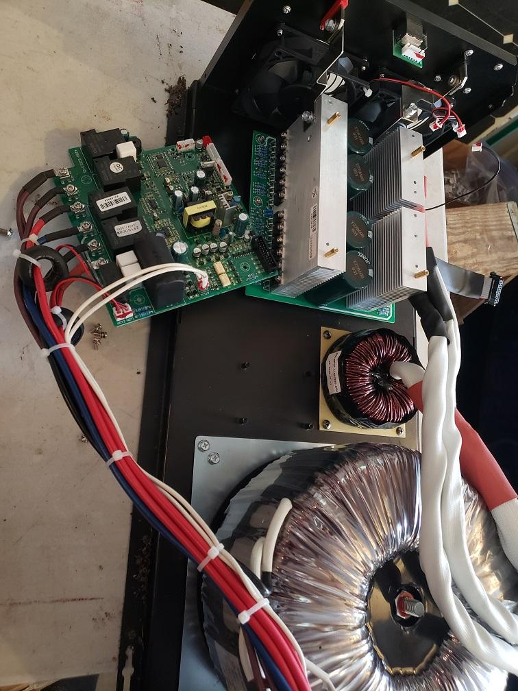 |
||||
| phil99 Guru Joined: 11/02/2018 Location: AustraliaPosts: 1783 |
Instead of a single fat wire they have used a bundle of thin wires to do the same thing. It makes winding easier and minimises the "skin effect" to get a lower resistance at the high switching frequency. |
||||
| rustyrotors Newbie Joined: 07/01/2023 Location: United StatesPosts: 31 |
correct, swap both power and control boards out and reuse the choke and trans. the chinese boards also power on with a closed contact like you want (open = off, closed = on) if you want to get adventurous, you could make your own board to adapt the egs002 to your ampinvt power board instead of using the chinese power board. take a look at the EG8010 datasheet, the chinese boards are basically direct copy of the application schematic. minimally all the egs002 module really needs is 5V, 12V power supply and an AC feedback circuit for the Vfb pin. you would have to find out the pinout to your power board to match the gate signals to the egs002 |
||||
| InPhase Senior Member Joined: 15/12/2020 Location: United StatesPosts: 178 |
I built a "split phase" 120/240 V inverter based on Poida's Nanoverter. The only thing different from the Aussie version is a third wire from the transformer secondary. Feedback voltage should be taken across the 240 volt winding. Making sure your two secondaries are well balanced will ensure a stable 120 volts on either side. |
||||
| JohnTaves Newbie Joined: 01/11/2023 Location: United StatesPosts: 19 |
I have no idea how one would keep the two secondaries well balanced. The transformer will allow power to whatever leg needs it, right? So, if I am thinking straight, then given that the 240V is monitored, you also need to monitor one of the 120V legs and somehow keep it at 120V, right? |
||||
| Page 1 of 2 |
|||||
