
|
|
Forum Index : Electronics : BMS design
| Author | Message | ||||
| JohnTaves Newbie Joined: 01/11/2023 Location: United StatesPosts: 19 |
I find that the BMS and charge controller offerings are just wrong for lithium packs, so I made my own. If anyone is interested in this speak up. Background: It makes no sense to have the solar charge controller, or inverter/charger, using pack voltage to decide when to charge or not charge. When any one cell reaches the top or bottom cut-off V, charging or loads should be stopped. In other words, the BMS should be the brains of any lithium based system. The off-the-shelf BMS offerings combine the disconnect circuit and the brains into one package. This is stupid. The brains are independent of the amps and voltage (number of cells in series). A pack disconnect SSR should be sold separately depending on amps and voltage your application requires. It should take a simple 2 wire on/off open/closed connection from the brains. In other words, sell one product the BMS-brains, and sell a line of simple disconnects for different amps/volts. (I do not have a pack disconnect.) The charge controller doesn't need any brains. It should either deliver the current or stop depending on the signal from the brains. Many applications can buy panels that match the max power point to the pack voltage so that all you need is a simple SSR+diode to connect the panels to the battery. In addition I got frustrated with the rats nest of wires from the cells to the BMS. Solution: I made two esp32 based boards. One, the cell module, measures the pack voltage and temperature, and sends the info via bluetooth to the controller board. The controller board has a pile of SSRs to control things, a CAN connector, and bluetooth and wifi. The cell module, has the form factor where you simply bolt it to the terminals on a prismatic cell that you buy from alibaba. The temp sensor does require you to wire a thermister and tape it to the cell. This board has 2 20ohm resistors in parallel that the software will turn on, potentially for hours, to give that cell a haircut if it is the first cell to reach the top V. The software can ensure that no one cell is always the one to reach the top V. These report their measurements every 2 seconds, and are asleep between measurements. After I implemented the sleep feature, I was unable to measure the amps. Prior to that it matched the expected ESP32 drain of a few tens of milliamps. Nobody will get excited about the ability of the esp32's A2Ds, but I find them totally acceptable for measuring cell voltage. They seem good to about +-.01V. I figure that I have no need to run these cells up to 3.65V which is supposedly the max. I stop at 3.5V so it makes no difference if the cell was really 3.52 or 3.48. The controller board has 2 esp32s. I got tired of trying to get a single esp32 to do both the wifi and bluetooth. There are 16 total SSR outputs that are used to turn on/off loads and charging. There is a CAN bus that I use to capture the data from 2 Reidon SSD digital shunts. One shunt measures the pack voltage and amps, and another measures the solar amps. It has input for 4 different resistance measurements. Two are used for the temperature in the front and rear of the RV and control the 2 furnaces, one of which will heat the water bay where the batteries are to ensure neither freezes. Another reads the water level resistor in the fresh water tank, and another reads the propane gas level resistor. The software provides a web page where you set the # of cells and the various cut-offs and recovery values. The temperatures and gas and water levels are shown on the web page (the screen shots are from an earlier version, so no water or gas level). The software does coulomb counting to monitor pack state of charge. I have it set to stop charging at 95% and turn charging on after it drops below 90%. This means that the pack is almost never at 100%. I have my settings such that 100% is when any one cell has hit 3.5V and the pack amperage is less than 12 (I have an 2p8s 280ah so 13kwh total). It will turn off the main cabin air conditioning if the pack state of charge goes below a certain %, and same with the electric water heater, which reverts to gas. When any one cell drops below the minimum voltage, the DC/DC converter is shut off along with the inverter resulting in only the current necessary to power these boards. Because the coulomb counting will accumulate error, I occasionally run the pack to 100%. The software has not been fully implemented where it will monitor what cell hits the top and then turn on that cell's drain resistor to give that cell a haircut to ensure that it will not be the one to hit the top next time. I just do this manually. Whenever I hit the goto-100% button, I check afterwards to see what cell was the top dog, and turn on its resistor for several hours. 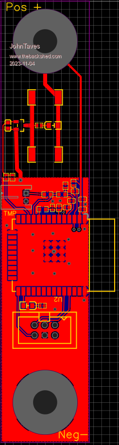 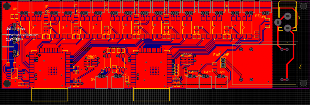 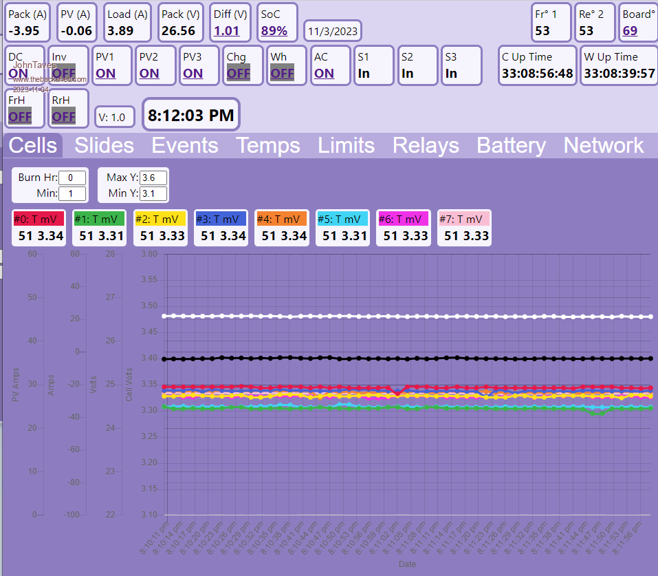 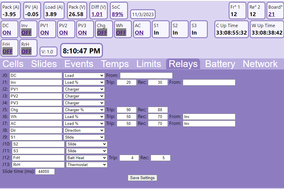 |
||||
Revlac Guru Joined: 31/12/2016 Location: AustraliaPosts: 961 |
First of all, Well done building your own BMS. Its been working fine for many people for many years, some systems that have an AIO use grid charging and closed loop communication between inverter charger and BMS would be favourable. Offgrid can run fine without it, the BMS is only used as a last resort, last line of defence. There are a few BMS units reviewed by Andy https://off-grid-garage.com/battery-management-systems-bms/ Cheers Aaron Off The Grid |
||||
| JohnTaves Newbie Joined: 01/11/2023 Location: United StatesPosts: 19 |
I was not very clear. I totally agree that this lead-acid product architecture is working. I am saying that these products are inefficient in the market place. Too many options and variations and complexity is the result of using the lead-acid architecture. The BMS as a last line of defense is an excuse given the product offerings and not really a rational design if one were to start with Lithium. The simple concept of separating the BMS brains from the disconnect circuit and selling them separately enables one to offer say 2-3 different brains with different user interfaces (wifi, bluetooth, lcd), and separately a range of disconnects to handle the different amps/volts. That change right there whacks your product offerings from NxM to N+M. Essentially the brains of any non-portable lithium based system can be a single product, then the surrounding components can all be dumb. Battery disconnects (to provide "last line of defense"), shunts, inverters, DC/DC converters, chargers and solar chargers can be offered with just amps/voltage sizing options. These would all have simple on/off two wire connectors. (Although, I would probably take the extra step to make them all bluetooth to eliminate those wires. If the component does not receive a "keep charging" message every n seconds, then the component will stop.) The complexity of customer support is dramatically reduced because you eliminate discussions about setting up the inverter, bms, and charge controllers and whether they are playing nicely together. You also eliminate the pressing need to balance the cells. Balancing the cells becomes nothing more than achieving maximum capacity and not about ensuring the last line of defense does not trigger for lack of balance. I am not saying that builds that use equipment that descended from lead-acid are inadequate. I'm saying all of this to see if anyone is interested in providing that range of products. |
||||
| nickskethisniks Guru Joined: 17/10/2017 Location: BelgiumPosts: 411 |
hi, that is a very nice effort you did there, did you write the code in the arduino environment? |
||||
| rustyrotors Newbie Joined: 07/01/2023 Location: United StatesPosts: 31 |
i like it. you are right, the current solar state of the art is a bit silly, creates problems not just for lithium but lead acid too. for example inverter low voltage cutoffs that are too low to prevent damage and too high to allow high loads at low state of charge. or chargers that only track energy out of the charger, and not actual energy into the battery. if there is significant inverter load, charger thinks battery is accepting current, and ends up overcharging the battery. its frustrating trying to decide on settings, it ends up being a poor compromise between longevity and performance but yea there needs to be a system controller that keeps track of energy transfer between components, and not with just voltage triggers. I like your modular switching idea, to match voltage/current requirements of the system. i think you could probably piece something together like this from victron components, but even their stuff looks to be overly complex and expensive but i do not think the bms should be included in the system controller. each component should be able to protect itself from damage, including the battery with voltage, current cutoffs and active balancing, independent of the system, like a "last line of defense." for example the inverter should still have voltage/current cutoffs, but with the purpose of protecting inverter electronics, not the battery. The system controller should have priority control over energy transfer to/from each component: what, when, and how much Edited 2023-11-06 03:24 by rustyrotors |
||||
| JohnTaves Newbie Joined: 01/11/2023 Location: United StatesPosts: 19 |
I used VScode, platformio, and arduino framework. Although to get the full control I needed to get the esp32 to go to sleep on the battery monitor, I used the espidf framework. |
||||
| JohnTaves Newbie Joined: 01/11/2023 Location: United StatesPosts: 19 |
Sure, each component should have its own protection. So, an inverter would shut off when it detects over current or over voltage that would wreck itself. But it does not need to have settings that will attempt to protect the battery. That is just a waste of circuits and complexity as you identified. More importantly, it should not be able to deliver charge, or be a load, without a closed circuit from a device that has cell information. With respect to the battery, separating the brains (CPU, cell monitoring, and UI) from the simple circuit that will disconnect the battery, changes nothing with respect to "last line of defense" for the battery. It simply reduces the number of product offerings from NxM to N+M. Simplicity is safer than complexity, but combining the brains with that pack cut-off device is not simpler. The exact same set of circuits exists in both the combined and the separate situation. Hiding the cell voltage information inside this "last line of defense" is a waste. It forces additional complexity. I have no problem with a battery that comes with its own BMS (e.g. battleborn). But attaching other charge/load components that know nothing about the cell voltages and that do not depend upon a trivial open/close circuit to turn on, is not more safe for the battery. For example, a Victron MPPT is a complex device that does not have cell information and yet it can deliver a charge. It can do that without receiving any positive signal from a device that does have cell information. It is poor reasoning to conclude that, because the Victron will stop when it detects pack voltage is too high, it is therefore another line of defense. It should be viewed as additional complexity that has the potential to F'up and deliver too much power. I am not saying that I or you should not trust a Victron combined with a battleborn. I am saying that it is a bogus argument to say that it is more safe for the batteries than a simpler system where the charge controller can only deliver power if a simple circuit is closed. My Ampinvt inverter is a fine example of this problem. I know that somewhere inside this unit is a wire that when disconnected, the inverter cannot draw current. However, that circuit is not available to me. It is buried behind settings for minimum pack voltage, temperature, and a momentary on/off switch. The fact that it has battery under voltage shut off is actually the problem. If they had not even attempted to worry about that, I would have a simple on/off switch that would only be closed when the BMS says the cells can take a load. Edited 2023-11-06 05:59 by JohnTaves |
||||
| JohnTaves Newbie Joined: 01/11/2023 Location: United StatesPosts: 19 |
Maybe another way to say the above, is to say that "last line of defense" is saying that there are other lines of defense. My point is that those other lines of defense are really a false sense of security. A device that can deliver charge without knowing the individual cell's status, should not be viewed as some line of defense. It should be viewed as a potential failure point. |
||||
| Ziki_the Newbie Joined: 13/04/2023 Location: YugoslaviaPosts: 28 |
@JohnTaves Very neatly done, I really like it. A lot of effort has been put in, congratulations. :) Pozdrav iz Srbije |
||||
| nickskethisniks Guru Joined: 17/10/2017 Location: BelgiumPosts: 411 |
Hi JohnTaves, I saw you post on Murphy s friend active balancer, I could not really place it in perspective. So I wondered a few days if I should start a discussion or not because he didn't really want to. So feel free to ignore my probably long post, but I think we are all here to show our projects and to learn from another. I myself will always be open for feedback if we do it with respect. I know you made your system with a certain reason and I think we are more or less on the same page, it starts on cell level monitored by a master brain. Let this unit play with the slaves. The hardware that's were we differ. Murphy showed us his active balancer, in my view a part of the BMS, like you have your bleeding off resistors (passive balancer). I don't know his system and never asked but if I look at his pictures I clearly see wires coming from each individual cell (not used for his balancer), if Warpspeed designed his balancer, he probably would have gave him also advice for his master, or BMS. With the things I already saw from Murphy I would expect a nice no nonsense bms behind the wheel. As far as complicated, well a few years ago I made something much more complicated, but the system behind it is actually quite simple and similar. I made a working proof of concept with individual pcb's per cell (somewhere to be find on this forum), each having a push pull circuit with transformer, the energy was exchanged with a central "hf AC bus". I have packs with different capacity cells (age) that I still wanted to use. Was it useful? I learned a lot that's for sure, I think it was fun thinking about a solution for a certain problem. Probably more expensive then adding new cells for compensating the unusable energy in the strong cells. It's all about perspective and background, you didn't want to use 17 sensing wires, well you use at least 16 ESP's. And honestly I'm a bit jealous on the programming skills you must have to pull this off. For me this would be really challenging and probably to much to ask, I could even say overly complicated (for me) only to avoid those 17 wires. So I used only 1 µC with 1 ADC and 16 dual opto mosfets to create my bms (also somewhere on this forum), I don't mind the 17 wires, they could be placed very neat in my opinion. I know my system is very reliable because of the limited number of components used, there is only 1 ADC, so if it's not accurate, each cell is measured with the same accuracy. If their would be a problem it will be easy to solve. Those were my main constraints, I will probably make a new version in the future but based on the same principle, pimped with an esp. But I'm sure we both had fun and learned a lot doing it our way. Why an active balancer? Murphy stated he's using a very old out of balance battery pack, a big deviation in cell capacity. With an active balancer you can use all the energy in the pack, IF the balancer is strong enough during a big load. It might even bring the cell capacity closer to each other because the strong cells are more heavily loaded (not proven but who knows). You think their is no use of constantly have an active balancer, passive or active? I would not use an active balancer with new cells, it adds to much points of failure, the chinese ali express versions I've tested so far are not even that accurate and I would not recommend to use. But I use an active balancer for already 4 years now with 12V LA batteries in a pack that I could recommend, they keep the pack well balanced. You probably have a new battery and cell capacity deviation is no issue, but I think your system can benefit if you could start balancing once a certain difference occurs between cells. And not wait until a cell hits 3.5V to start balancing, you can probably save a lot of equalizing time starting the balancing sooner. Eventually when the battery pack gets older this could be important. You also see this implemented in RC lipo chargers, balancing starts immediately if a certain threshold is met. I know all cells have a slightly different voltage curve so there is no point in doing that with 1mV. Your ADC's are probably not accurate enough? But wasn't that problem with the esp32 with very low and high voltages on the adc and in the middle it was pretty linear, so actually not a problem? I suppose you use a voltage divider? Edited 2023-11-19 09:28 by nickskethisniks |
||||
| JohnTaves Newbie Joined: 01/11/2023 Location: United StatesPosts: 19 |
I Agree. I also think that it is cool that it is scalable to any pack. The esp32 library I use for the bluetooth only handles 8 devices, which is fine for my 24V pack. However, I kicked out another design of the main board that has just 1 esp32, but allows you to stack them. This means you can make a 48V system by stacking 3 controllers. 1 will do the wifi, providing the UI. The other 2 will gather the cell info. Each controller is identical, so you end up getting more relays and more voltage sensor with each board. I agree this is not superior to 17 wires, or rather it is superior in the one-design-scalable sense which may not have any value. I had the notion that I would put this up as a DIY open source thing, like the Stuart Pittaway DIY BMS, but never got off my butt to actually do it. It will run the resistor for as many hours as you want, regardless of cell voltage. The first cell to hit 3.5V tells me what cell to give a hair cut to. The idea is that I don't want the same cell hitting the max every time. That is more important than attempting to squeak out the maximum capacity. I have never run my pack to the bottom. I have no idea what cell capacity deviation I have. I suspect my use case is pretty common. If the battery is getting low, I use gas heat and limit the high energy devices, or I find a way to plug in. If the mix of battery capacity, solar array size, and weather means I am spending too much time running gas, the solution is to add more PV panels and Li cells. It does not make much sense to attempt to recover some capacity, that may or may not exist, from the pack. |
||||
| MoonLynx Newbie Joined: 16/02/2024 Location: CanadaPosts: 1 |
I know this is old thread, but I am new member, so guess it's all new to me  I think ESP is overkill for the cells monitoring, but overall approach makes sense. I also like this development from Stuart Pittaway : https://www.youtube.com/@StuartPittaway , he actually started same way and latest development got to the split boards for controller and cell monitors...but later is a single board for 16s. Doesn't remove ability to use single monitors on every cell and allows scalability in any direction. BTW: I hit the same issue with single cell ruining the whole capacity and charging for the battery ... So I am keen to try Stuart build for my application before actually reassembling the battery with more similar by parameters cells... Edited 2024-04-05 13:18 by MoonLynx |
||||
