Notice. New forum software under development. It's going to miss a few functions and look a bit ugly for a while, but I'm working on it full time now as the old forum was too unstable. Couple days, all good. If you notice any issues, please contact me.
rogerdw Guru Joined: 22/10/2019 Location: AustraliaPosts: 795
Posted: 09:52am 21 Nov 2023
Copy link to clipboard
Print this post
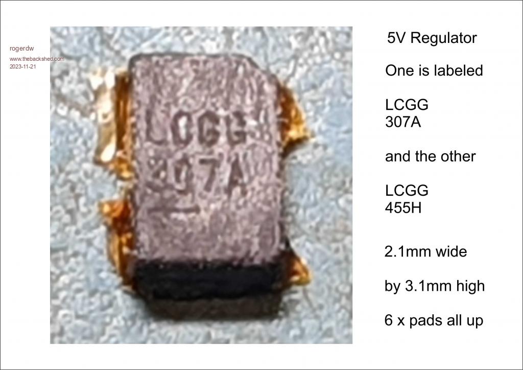
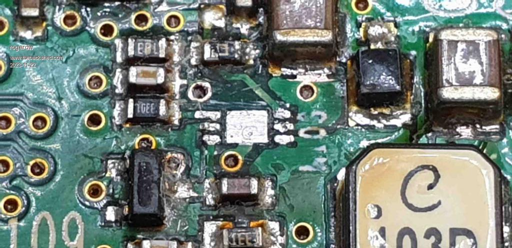
Hi guys, I'm trying to ID a 5V regulator and am not having any success.
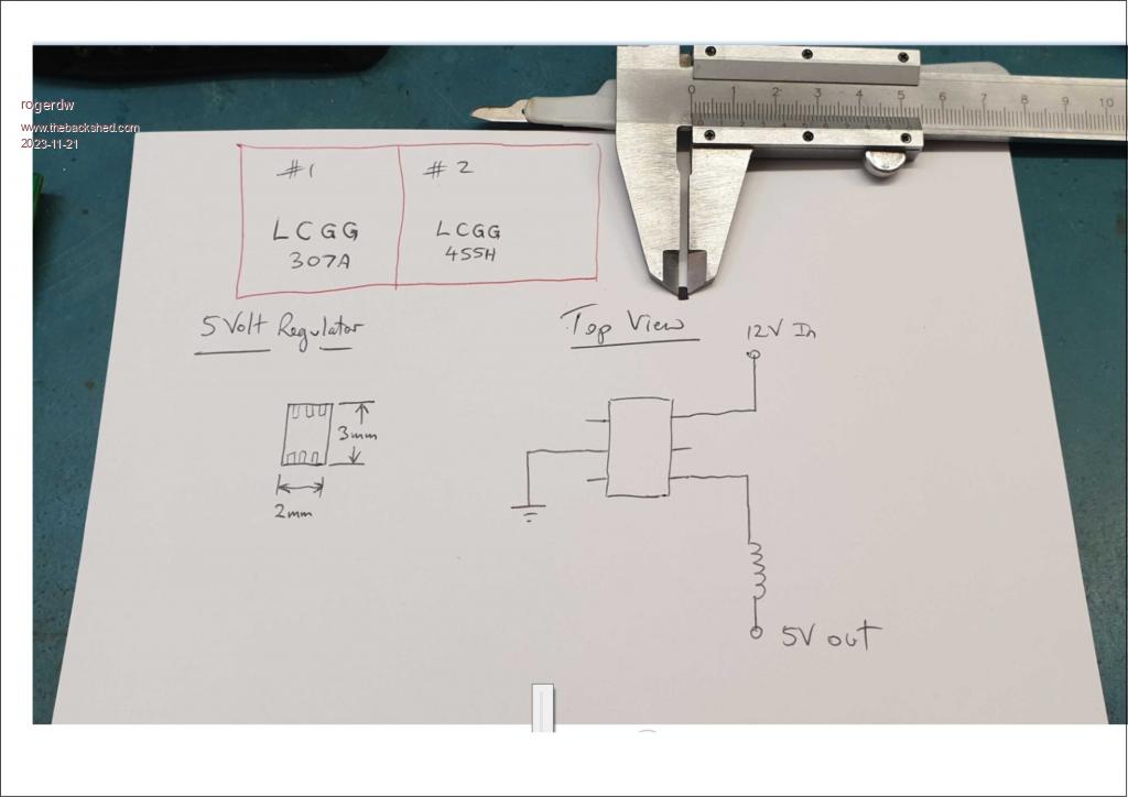
It's only 2.1mm x 3.1mm and with 6 pads, no legs.
Thanks for any help
Cheers, Roger
phil99 Guru Joined: 11/02/2018 Location: AustraliaPosts: 1783
Posted: 11:35am 21 Nov 2023
Copy link to clipboard
Print this post
The codes on small SMD devices aren't always related to the type number. They can be a be anything a large customer wants them to be. The same type may have different codes for each customer.
From your circuit it seems to be an adjustable switch-mode regulator. The top left pin is the V-feedback pin and from the 18k / 3.3k divider its Vref is about 0.8V.
Do a search for any one with the same pin-out and rated for 15V or more. Edited 2023-11-21 21:38 by phil99
wiseguy Guru Joined: 21/06/2018 Location: AustraliaPosts: 995
Posted: 09:51pm 21 Nov 2023
Copy link to clipboard
Print this post
Hi Roger maybe some of the following would/could suit ? All ex Digikey
ST1S03 LT3503EDCB#TRMPBF LT3493EDCB#TRMPBF TPS40222DRPR LM2734ZSD/NOPBIf at first you dont succeed, I suggest you avoid sky diving.... Cheers Mike
rogerdw Guru Joined: 22/10/2019 Location: AustraliaPosts: 795
Posted: 10:04pm 21 Nov 2023
Copy link to clipboard
Print this post
Thanks Phil, I was a little surprised that I couldn't find any info, I usually can if I persevere.
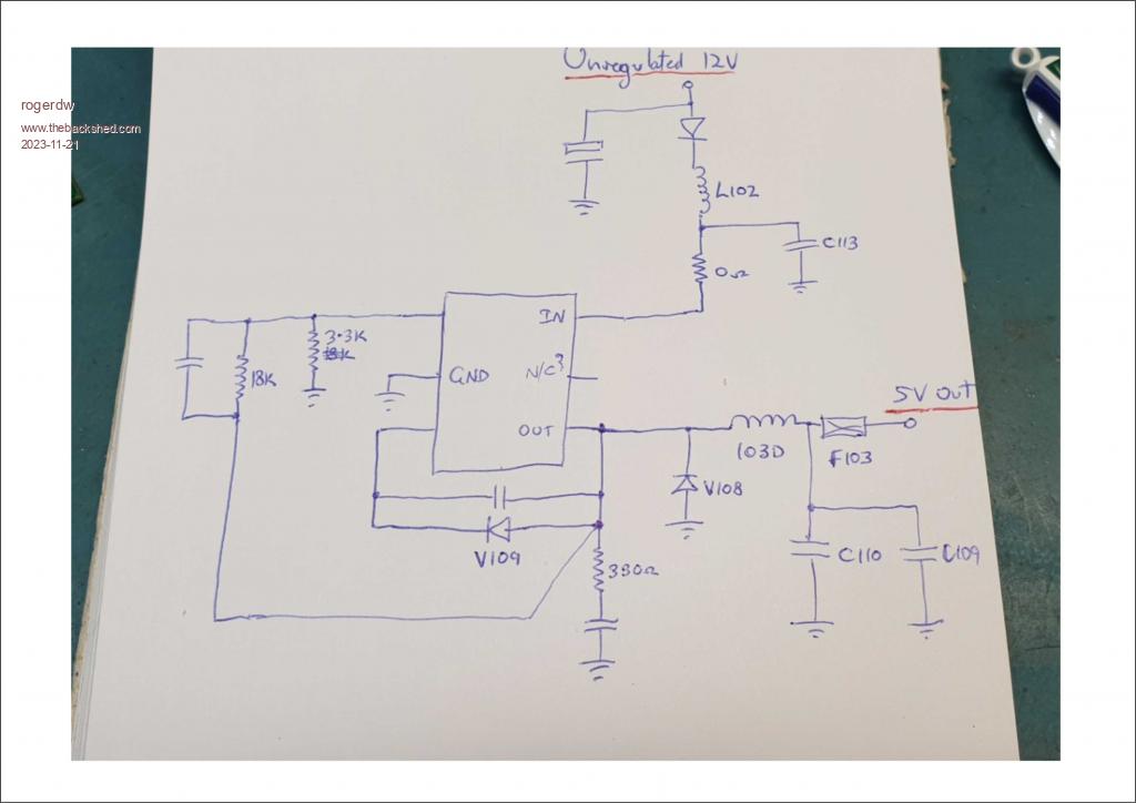
I only drew out the full circuit after I'd given up looking through datasheets, so hadn't even considered that it might be a variable regulator. I was assuming it would be a 5V one. The board also has 3.3V one (similar but still a different type and size) which is supplied by the 5V line.
I ended up fitting one off another scrapped board, which fixed the problem, but I'd still like to keep some spares for future potential faults.
I'll check out some more datasheets this morning but this time I won't ignore the variable output ones. Thanks again.Cheers, Roger
rogerdw Guru Joined: 22/10/2019 Location: AustraliaPosts: 795
Posted: 10:09pm 21 Nov 2023
Copy link to clipboard
Print this post
Thanks for the examples Mike, that may just save me a heap of time.
I've realised I probably caused myself a heap of grief by assuming it was a set output regulator and ignoring the datasheets of all the variable ones. No wonder I couldn't find one with a pinout that looked similar. Cheers, Roger
phil99 Guru Joined: 11/02/2018 Location: AustraliaPosts: 1783
Posted: 10:21pm 21 Nov 2023
Copy link to clipboard
Print this post
Now you have it working, to be certain you are searching for one with the right Vref measure the feedback pin voltage. When operating within normal limits it will be the same as Vref.
rogerdw Guru Joined: 22/10/2019 Location: AustraliaPosts: 795
Posted: 11:57pm 21 Nov 2023
Copy link to clipboard
Print this post
Well thanks very much again Phil and Mike.
First off, Vref or FB measures .782v
I went through the list you supplied Mike and none showed the layout I thought I had, so I had a closer look and found that while I thought pin 6 was VIN it was actually pin 5 ... and pin 6 (Shutdown) was tied to VIN via a zero ohm resistor because the function is not used.
So it looks like the LT3503 may be suitable as it also says it regulates its feedback pin to 780mV.
I corrected the circuit diagram and added a few details.
This all brings out the fact that even though I enjoy working on my own, having others around to bounce ideas off is probably the single biggest thing that I miss ... but after 35 years and getting close to retirement age ... it's probably not going to change any time soon. Haha, actually I just hit retirement age today!!!
Cheers, Roger
phil99 Guru Joined: 11/02/2018 Location: AustraliaPosts: 1783
Posted: 12:45am 22 Nov 2023
Copy link to clipboard
Print this post
One more adjustment to your circuit diagram. The 18k divider resistor and anode of V109 go to the load side of the output inductor, not the Out pin.
Murphy's friend Guru Joined: 04/10/2019 Location: AustraliaPosts: 583
Posted: 06:54am 22 Nov 2023
Copy link to clipboard
Print this post
Does that mean a HAPPY BIRTHDAY wish is in order?
I suppose working for yourself is kind of what I was doing since retiring early (at 60) but just for keeping busy, not working for a living.
rogerdw Guru Joined: 22/10/2019 Location: AustraliaPosts: 795
Posted: 01:31pm 22 Nov 2023
Copy link to clipboard
Print this post
Thanks again Phil, I think I have it worked out now. It's a bit tricky trying to measure everything while still in circuit ... especially when there's a few coils and 0 ohm resistors involved.
Even worse is the rotten conformal coating which is almost impenetrable. I sometimes take to a board with a tiny engraving bit to be able to measure accurately ... and I have an old Polar device which measures very low ohms, but you still have to pay attention.
And yes, thanks Klaus, it is my birthday today. I just added it up and it is more like 38 years working alone. I've generally enjoyed it and used to be very disciplined but am getting pretty slack in my old age. Winding down I suppose.Cheers, Roger
Bryan1 Guru Joined: 22/02/2006 Location: AustraliaPosts: 1209
Posted: 07:52am 23 Nov 2023
Copy link to clipboard
Print this post
Hi Rodger, Happy Birthday mate now just remember life does begin at 40 and when one thinks retirement will be easy one will be busier than before.
I'm up at Mt Isa and will be home Sunday night and it will be great to catch up again.
Cheers Bryan
rogerdw Guru Joined: 22/10/2019 Location: AustraliaPosts: 795
Posted: 09:42am 23 Nov 2023
Copy link to clipboard
Print this post
Thanks for the birthday wishes Bryan. It crept around fairly quickly and I haven't made any plans yet to quit work. I really need to get some financial advice before I make too many changes.
Sounds like you get around a bit ... Mt Isa ... I assume it's work related.
Yes it would be good to catch up again. Give me a call or a msg whenever you're free and we can organise a get together.Cheers, Roger


 Thanks again.
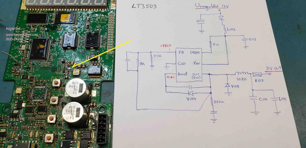

 now just remember life does begin at 40 and when one thinks retirement will be easy one will be busier than before.