
|
|
Forum Index : Electronics : trimmer issue charge controller
| Author | Message | ||||
| irishron40 Senior Member Joined: 22/09/2014 Location: IrelandPosts: 246 |
hello I would appreciate a little help as I am lost as what is happening i build this charge controller( https://www.thebackshed.com/windmill/articles/TL084-Controller.asp ) everything seems to be working beside the low voltage relay release from dumping the relay clicks in to dump at 14.91 vdc but when i lower voltage the relay clicks out again at 14.84 vdc I cannot seem to be able to get it to release at a lower voltage like 12.6 vdc anyone has any ideas as to why? thank you. ron |
||||
| irishron40 Senior Member Joined: 22/09/2014 Location: IrelandPosts: 246 |
anyone please? thanks ron |
||||
| pd-- Senior Member Joined: 11/12/2020 Location: AustraliaPosts: 122 |
What happens when you adjust the 10k pot connected to pin 5 of the TL084. Sum voltage readings around TL084 2/4 might shed sum light. Have you tested all the resisters are the correct value. 12.6 is way to low 13.8 would be more like it. |
||||
| poida Guru Joined: 02/02/2017 Location: AustraliaPosts: 1388 |
let's work through this together. I am not good with analog stuff. (It's going to be a lot of thinking out aloud) 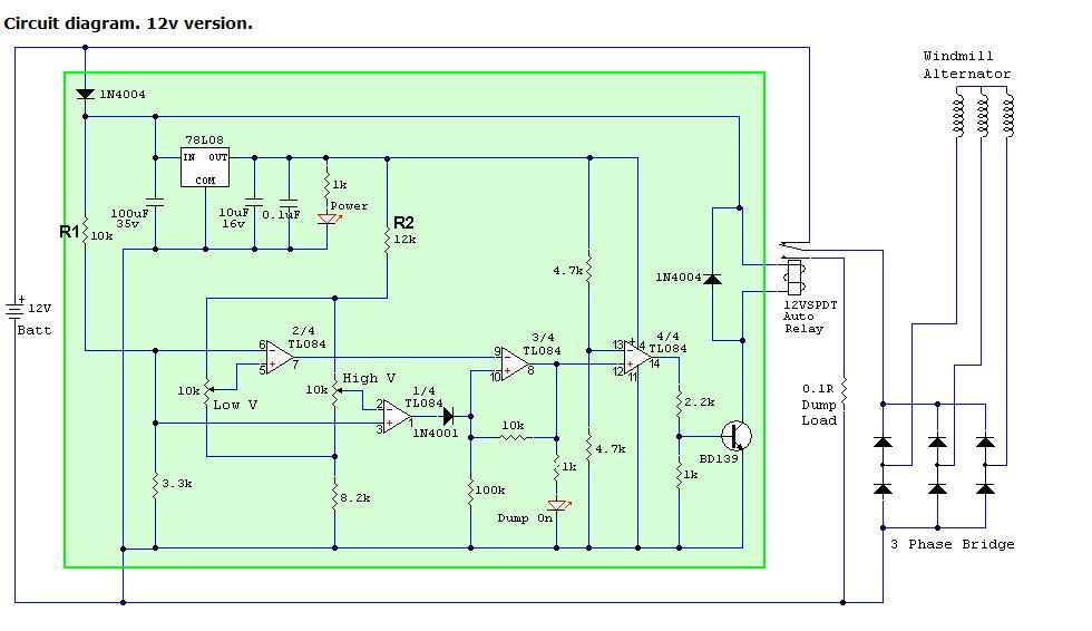 First thing I would do is prove the 8V is in fact 8V that supplies everything. I want to see it be 8V when switching the relay or not. once that is done, The circuit appears to be 2 comparators (2/4 and 1/4) , one amp with hysteresis (3/4) and another comparator (4/4) that drives the BJT and relay You could check that both low and high trim pots can turn on and off the their comparitor's outputs. These outputs will be a bit less than 8V when "on" comparator 2/4 and 1/4 both share a reference voltage that is compared with the trimpot's voltage. The ref voltage comes from the battery is divided by the 10K and 3.3K divider. the divider's output is 0.248V per Volt on the nominal 12V input. 12V input will give 2.977 V This should appear on pin 6 and pin 3 of the quad op-amp. What battery voltage are you testing with? check for your divided voltage. trimpots can output a voltage from 2.172 to 4.821 Volts and this depends on the 8V supply. This corresponds to input voltages from the battery of 8.76 to 19.44 Volts. Maybe prove you have these voltages at either end of the trimpot's positions. That is a start for my understanding of how it's supposed to work. If we have all the above OK then it's time to look at the 3/4 op amp and how it's supposed to function wronger than a phone book full of wrong phone numbers |
||||
| irishron40 Senior Member Joined: 22/09/2014 Location: IrelandPosts: 246 |
thank you for your reply nothing really when adjust the high pot. when i adjust the low pot it will change the voltage from 14.91 all resistors right vallue ron |
||||
| phil99 Guru Joined: 11/02/2018 Location: AustraliaPosts: 1783 |
Further information on testing that circuit here. https://www.thebackshed.com/forum/ViewTopic.php?FID=2&TID=16338&LastEntry=Y#211422#211371 |
||||
| phil99 Guru Joined: 11/02/2018 Location: AustraliaPosts: 1783 |
As the pots are in parallel I get 2.60V to 4.19V (assuming the regulator output is 8.00V) but the principle is the same. With your multi-meter (-) probe on Bat- and the (+) probe on the middle pin of each pot the voltage must vary between those limits as you rotate the pots. If not you must find and fix that problem before you can go any further. Report back here what voltages you get for the regulator output and at max. and min. for each pot. |
||||
| irishron40 Senior Member Joined: 22/09/2014 Location: IrelandPosts: 246 |
ok thank you all. i have a supply off 8.1 volt I have on the high trim a range from 2.56 volt to 4.20 volt I have on the low trim pot a range of 2.57 volt to 4.20 volt i found however a possible problem with one of the 4004 diodes its the one running from centre pin bd139 to left pin 78L08 when i test diode in circuit i have voltage drop of 0.081 and reversed 0.082 diode test perfect when soldered out of circuit ron |
||||
| irishron40 Senior Member Joined: 22/09/2014 Location: IrelandPosts: 246 |
tl084 pin voltages 1 7.35 2 2.57-4.20 depending on pot adjustment 3 2.88 4 8.02 5 2.56-4.20 depending on pot adjustment 6 2.88 7 1.49 8 7.35 9 1.49 10 6.90 11 16.8 --???? input from power supply is 12.42 volt , how could this be more 12 7.35 13 4.00 14 6.65 ron |
||||
| irishron40 Senior Member Joined: 22/09/2014 Location: IrelandPosts: 246 |
i dont know whats happening , but after typing all the vallues I connected it to power again and relay clicking out at 13.57 and engaging at 14.97 im at a loss whats going on thanks ron |
||||
| phil99 Guru Joined: 11/02/2018 Location: AustraliaPosts: 1783 |
That is normal, the diode is in parallel with the relay coil so a diode test won't give a correct result. Pin 11 is the ground pin for the IC so should read 0V. Probably a bad connection / solder joint somewhere. That it is now working is probably related to the same bad connection. Probing around may have temporarily fixed it. For reliability you will need to find and permanently fix it. Start by checking pin 11 then all other connections to Bat(-). If they are all good check all the others. |
||||
| irishron40 Senior Member Joined: 22/09/2014 Location: IrelandPosts: 246 |
could i set high to 17 volt? |
||||
| phil99 Guru Joined: 11/02/2018 Location: AustraliaPosts: 1783 |
R1 sets the operating range. Increasing it from 10k to 15k may do what you want. However the point of this circuit is to protect the battery from overcharging. If you are using a 12V Lead Acid of any type don't go over 14.5V. For a longer life 14.0 to 14.2V is better. For longest life, 13.7V. |
||||
