
|
|
Forum Index : Electronics : ?useing a TL494 300KHz instead of 21.6KHz, PWM controller will???
| Author | Message | ||||
| sunwalker Newbie Joined: 17/11/2023 Location: AustraliaPosts: 7 |
I'm building a solar controller for ~>1000w, ~100v, ~13A from a plan that shows in the schematic a TL494 21.6KHz, PWM controller. I'm using EasyEDA for the PCB & probably the parts, going through their available parts list I can't find a TL494 21.6KHz, PWM controller. There's plenty to chose from but none of the pins match the original plans, the closest I can find is 300KHz instead of 21.6KHz. But as this is new to me & I read online/search that the TL494 "The range of the operating frequency for this device is from 1kHz to 300kHz." So does that mean there is no 21.6KHz model they are all 300kHz, & operate as needed depending on the given input? If not & there is a 21.6KHz, what's the effect of using a 300kHz instead? thanks for any help. |
||||
Revlac Guru Joined: 31/12/2016 Location: AustraliaPosts: 961 |
Perhaps check the data sheet for TL494 I had a search, and these are available "TL494 PWM Controller Module Adjustable Generator 5V Frequency 500-100kHz" worth a look if you haven't already. Edit, just read this again, the Frequency should be adjustable to get what you want. I'm sure someone else will chime in with a bit more knowledge.  Edited 2023-12-04 22:34 by Revlac Cheers Aaron Off The Grid |
||||
| phil99 Guru Joined: 11/02/2018 Location: AustraliaPosts: 1783 |
From the TI datasheet. The oscillator Ct is pin 5 and Rt on pin 6. They set the frequency to what you require. The optimum speed depends on the power components. Semiconductor switching speed and inductor core losses are two that set a maximum limit. The lower the speed the bigger the inductor and capacitors need to be. |
||||
| sunwalker Newbie Joined: 17/11/2023 Location: AustraliaPosts: 7 |
thanks, that helps. I went back to the pdf data, "The frequency of the oscillator is programmed by selecting timing components R T and C T . The oscillator charges the external timing capacitor, C T , with a constant current, the value of which is determined by the external timing resistor, R T ." So the said resistor & capacitor determine the kHz value. |
||||
| rogerdw Guru Joined: 22/10/2019 Location: AustraliaPosts: 795 |
Is that the circuit that Warpspeed described over on the diysolar forum? Cheers, Roger |
||||
| sunwalker Newbie Joined: 17/11/2023 Location: AustraliaPosts: 7 |
Hi Roger, yeah have you been following it? I've been wanting to get a better understanding of circuits & it seemed a good project to start. diysolar forum doesn't get much into circuitry, its more off shelve buys. I'm upgrading my off grid 12v pwm system to a 48v 7500w, sys. I'm wanting something that I can repair, if need be, that said I think I could probably figure out & repair a cheap mppt if needed (maybe), just from what I've learnt so far from working through Warpspeed's design, & watching a lot of related video's & reading data sheets etc, as long as I don't have to deal with programing. |
||||
| nickskethisniks Guru Joined: 17/10/2017 Location: BelgiumPosts: 411 |
Can someone put a link to the diysolar forum? I Can't find it. |
||||
| Revlac Guru Joined: 31/12/2016 Location: AustraliaPosts: 961 |
https://diysolarforum.com/whats-new/posts/2578740/ You might have to dig through it a bit to find what your looking for. Cheers Aaron Off The Grid |
||||
| sunwalker Newbie Joined: 17/11/2023 Location: AustraliaPosts: 7 |
https://diysolarforum.com/threads/simple-home-made-analog-mppt-contoller.47057/ |
||||
| rogerdw Guru Joined: 22/10/2019 Location: AustraliaPosts: 795 |
Yes, I had read it through and may have considered trying it out ... but it means keeping the voltage pretty low ... and needing a controller on every string. That would mean a lot of controllers for me. Plus I had already spent a lot of time designing and laying out a version of Poida's MPPT based on wiseguy's board. And you're right about the guys over there ... their idea of DIY is to assemble a system using equipment they buy already made. Virtually no DIY at all Cheers, Roger |
||||
| nickskethisniks Guru Joined: 17/10/2017 Location: BelgiumPosts: 411 |
For people that don't like the idea of programming the arduino nano, you can actually combine the TL494 pwm IC and the backshed mppt controller powerboard, just a matter of making a small pcb with the IC and the right components/connector. You would even safe money because you don't need the current sensors anymore. @Roger, I don't know what your expectations are, or what you mean with low voltage, but you are right Warpspeed's PCB isn't designed for the currents the backshed controller can do. But I don't know what it's capable of to be honest. So you would need more of it, but I don't consider it as a bad thing when you have for example problems with shading or want a smaller and simple controller. I would still choose for the nano controller because of programmable parameters and the other whistles. It's also more efficient in bad weather conditions and that was my main concern because I can't fit a infinite amount of panels. Edited 2023-12-10 05:24 by nickskethisniks |
||||
| rogerdw Guru Joined: 22/10/2019 Location: AustraliaPosts: 795 |
Thanks Nick. I think if I was only building a small system I would definitely consider Warpspeed's design ... but I have 12kw of panels all in strings of three. That would mean I'd need 16 controllers.  As it is I am building four MPPTs and have them nearly finished. Still need to sort out the chokes and a cabinet for them all. I'm no expert on Arduinos but have just finished taking my son and grandson to an 8 week course on Arduinos, which I sat in on. I've managed to load the arduinos for them okay and made some adjustments to the various settings, so I'm making progress there too. 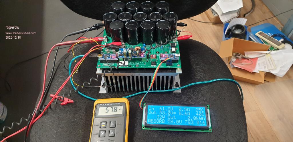 Cheers, Roger |
||||
| Murphy's friend Guru Joined: 04/10/2019 Location: AustraliaPosts: 583 |
Roger, with your warpverter you have an alternative if you happen to have a working GTI. I only have 5KW of solar for battery charging, 2KW of that is connected as 2 string panels feeding poida's nano MPPT. The other 3KW is arranged in 3 x 6 panel stings feeding a 3 sting GTI. As its AC output back charges flat out I use a voltage controlled relay to shut it off (a 30A relay cuts both poles of the AC connection) once the battery bank is full. It turns back on automatically after the battery voltage falls to a lower, pre set, level. This has worked well for me for a few years now. In your case it could save you several controllers and some solar cable. Besides, this ensures there is an alternative charging system available. |
||||
| rogerdw Guru Joined: 22/10/2019 Location: AustraliaPosts: 795 |
Hi Klaus, Yes you are right. The sad part is it took me years to wake up to those facts ... but by then I had committed to doing it this way. I don't envision needing any more solar ... but if ever I did, I would do exactly as you described ... in fact I have realised for ages now that if I was starting again, I would have aimed for a much smaller warpverter and done exactly that. Cheers, Roger |
||||
