
|
|
Forum Index : Electronics : fun with the inductor tester
| Author | Message | ||||
| poida Guru Joined: 02/02/2017 Location: AustraliaPosts: 1388 |
wronger than a phone book full of wrong phone numbers |
||||
| poida Guru Joined: 02/02/2017 Location: AustraliaPosts: 1388 |
I made a more proper inductor tester. looks like this: 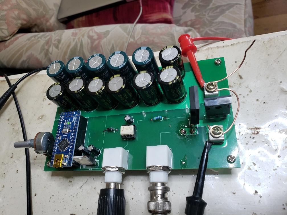 I felt it time to make a better one. One BNC is the pulse, 0-5V, taken from the Nano. The other BNC is the voltage across the current sense resistor. It uses a nice 0.02R shunt resistor for current sensing. I first tried a simple 1mm diameter copper wire, about 50mm long as the current sense but it has a strong temperature coefficient so it's resistance increases as it warms up. so I used this instead: 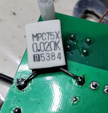 It works fine, getting a good trace of the inductor current. But I am interested in how this thing works. what woud happen if I used a 45mm long length of mm diameter copper as the "inductor". We see this: 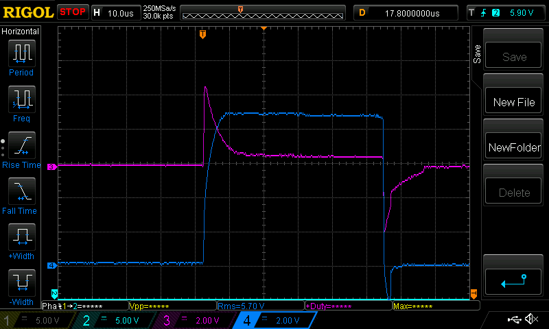 Blue is voltage across the 0.02R current sense. Pink is voltage across the copper wire. (The 0.02R resistor is in fact 0.0193 Ohms, after calibration. That 9V across it corresponds to 466 Amps!) I believe we can see the high resistance of the copper wire at the early stages of the pulse, and then it settles to a constant about 10uS. This seems to show to me the skin effect. The pulse sees a higher resistance initially then after 10-20uS it becomes a solid 1mm diameter copper wire. I do not have Litz wire but I do have some copper desoldering braid When tested it looks like this: 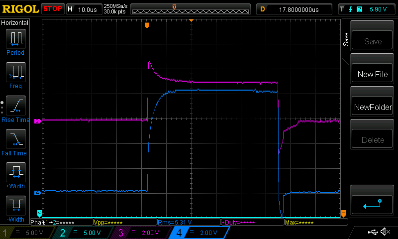 We can see a much smaller peak voltage across the wire compared with the 1mm solid wire. I always wanted to SEE the results of skin effect in a conductor. It's one thing to read about it in theory but another thing to see it in real world tests. I think this has some impact in our charge controller and inductor designs. The PWM drives put a strong fast rising pulse into the inductors and I wonder how they behave with the wide range of frequencies we blast into them. I suppose having conductors that have high resistance during the first 10s of microseconds means not a lot of the high frequency pulse energy will get through the primary winding of the inverter. It suggests to me that we don't need a choke core that needs to work well at high frequencies, since they are attenuated by skin effect of the wire we use in the choke construction. here is a 38.9 uH choke (as measured by the LCR meter) 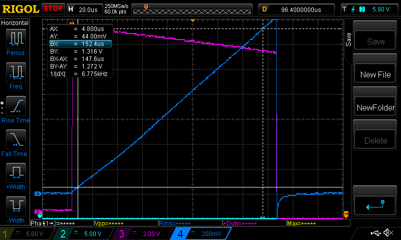 147uS pulse width, the current rises a total of 1.272V on the 0.0193R shunt = 66 Amps Test voltage is 15V but the Blue trace, the voltage across the choke, shows it drops about 2 volts during the pulse. So I average it out to 14V test voltage. L = t.V/A or 147 uS x 14V / 66 which is 31 uH Not real close but the current trace looks lovely and straight. wronger than a phone book full of wrong phone numbers |
||||
| poida Guru Joined: 02/02/2017 Location: AustraliaPosts: 1388 |
I know, the risetime of the FET is significant. Changing the FET's Gate resistor from 47R to zero does not change anything after the first 2 uS, it just adds a large amount of high frequency oscillation. The above tests were done with the 47R Gate resistor, to keep the traces looking smooth. here is the same 38.9 uH choke (using 7 turns with a TDK ferrite E core) but looking at the first 30 uS of the pulse. 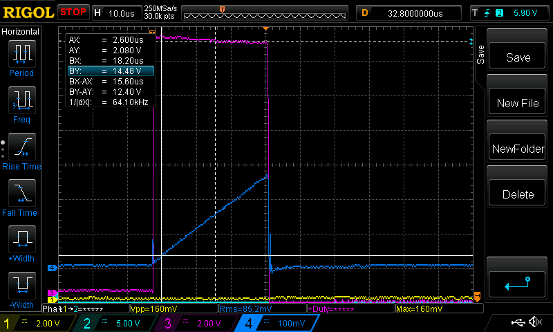 36.6us 0.282V on the current sense 14.5V across the choke at the mid point of the pulse (and 0.0193V/Amp for the current sense) 14.6 Amps L = 36.6us x 14.5V / 14.6 Amps = 36.3 uH that's a bit better. Maybe the ferrite core is non-linear? Edited 2024-01-09 21:31 by poida wronger than a phone book full of wrong phone numbers |
||||
| KeepIS Guru Joined: 13/10/2014 Location: AustraliaPosts: 1358 |
That's a really nice looking tester you've made, and very interesting findings. I really enjoy reading this kind of testing and thought provoking info, helps to get us thinking and looking deeper into our builds and design. I wish there was more time in the day to do this - or I'm just getting so dam slow these days. It reinforces the complexities of fast rise-time pulses in our high power inverters and Solar regulators. I always had a feeling that Skin effect played a part, but forgot about other changes like current flow and other fluctuations as harmonic content and skin effect dropped after the initial wavefront. I wonder of that may explain "some" of the strange behavior and instability that unlucky builders suffered, whereas identical circuits with slightly different build layout, cabling type and construction worked as expected - a source of frustration for some to say the least. On other hand, I can see where it may actually have helped in some cases. It's all too hard. Mike. |
||||
| poida Guru Joined: 02/02/2017 Location: AustraliaPosts: 1388 |
I agree, the next thing I want to see is the harmonic content of a fast square wave 57V pulse and how it will propagate through the inductor's conductor. This is part of my investigation (in thoughts only) about inductor design for our inverters and charge controllers. In other words, what do we need, what is not needed, what helps, what does not help. an example: large cross section conductors coupled with cores that do not do much at high frequencies might well be "good enough". OK. But why... I suspect that the choke's inductance, as measured by an LCR meter or whatever might not be so important as it's capacity to soak up high frequency energy and also not saturate at the designed power levels. Only testing will show some of this in my opinion. wronger than a phone book full of wrong phone numbers |
||||
| KeepIS Guru Joined: 13/10/2014 Location: AustraliaPosts: 1358 |
Yes, weeks of Choke testing and long term abuse / torture testing "above and beyond the call of duty" in my Inverter build appears to agree with your thinking: Look forward to any updates if you ever get time to follow through. . It's all too hard. Mike. |
||||
| nickskethisniks Guru Joined: 17/10/2017 Location: BelgiumPosts: 411 |
Nice project! Maybe you can notice/measure some capacitance of tranformers and inductors? |
||||
| poida Guru Joined: 02/02/2017 Location: AustraliaPosts: 1388 |
thanks for sharing your thoughts on this! I made my own Litz wire, using 0.25mm diameter magnet wire, which has a thin lacquer coating. here is the 1mm solid copper, the home made 16 strand Litz and the length of desoldering braid I used. 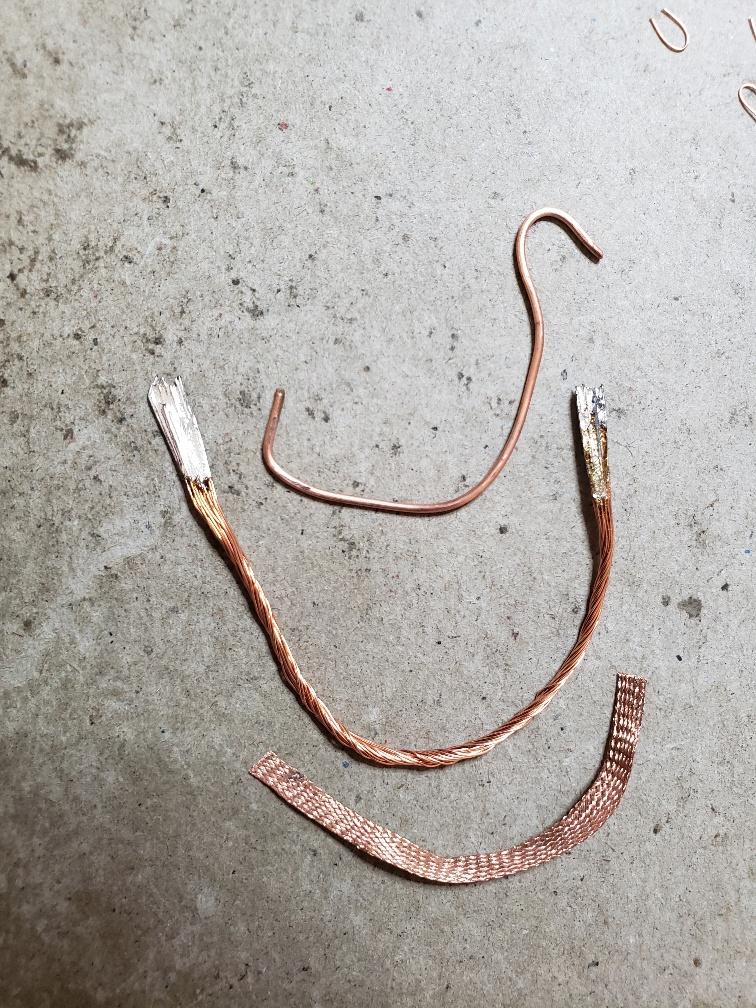 One fibre of the desoldering braid is 0.002" or 0.051mm in diameter. back to the choke tester and we see the home made Litz compared with the 1mm solid. I changed the vertical gain to make both curves line up after about 50 us. I had to do this since the length of the 3 test pieces are all different. The Blue curve is voltage across the 0.02R current sense. All tests showed current levels of around 450 Amps from about 40us onward. 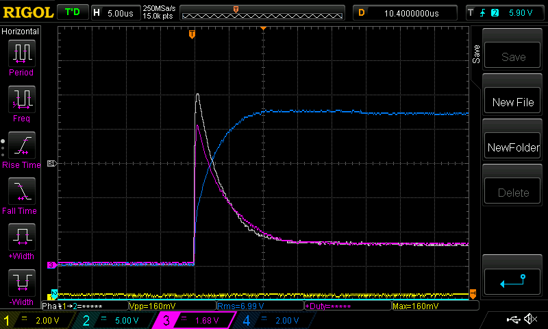 The White curve is 1mm solid, the Purple is the 16 strand home brew. You can see a reduced peak voltage and the peak is flattened a bit. This means the resistance of the 16 strand wire is a little lower during the early part of the pulse. this is what the desoldering braid look like: 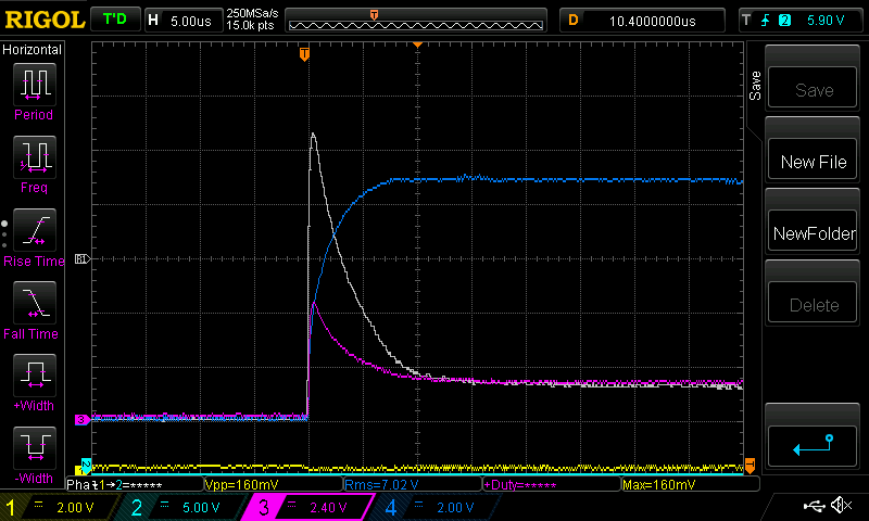 this is a huge difference. I saw this on the wikipedia page on skin effect This shows resistance of 0.51mm diameter copper wire as a function of frequency. 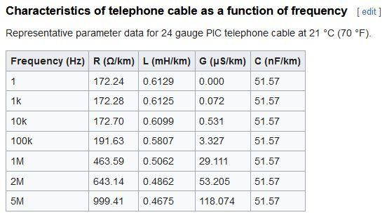 Once you get to 1MHz you will see it's nearly 3 times higher resistance I often see evidence of frequencies well over 1Mhz in the inverter and charge controller switching. The ringing during crossover is usually something like 1-5MHz It's time to look at the frequency and power components of this simple (not quite) square wave, with 15V amplitude and about 400 Amps. I want to break it down into 1 or 5us slices of time. Probably the first 1us will have a power spectrum with a lot of power in the hundreds and thousands of kHz. But also there will be a lot of DC. But at 50us, I expect to see purely DC and very little power above 100KHz wronger than a phone book full of wrong phone numbers |
||||
| KeepIS Guru Joined: 13/10/2014 Location: AustraliaPosts: 1358 |
That's interesting and I apologize for getting a bit off topic here. At RF frequencies as low as 1Mhz, copper braid is a very poor conductor because of the way the interleave weaving screws with the Skin effect. I carried out a test on short pieces of various heavy copper braid. The Test used them as a connection lead in a high power, high current, very low impedance resonant RF circuit. The braid introduced an R-Loss that destroyed the circuit Q, the braid got very hot, the 25mm copper tube resonant circuit was always stone cold. . Edited 2024-01-12 11:55 by KeepIS It's all too hard. Mike. |
||||
| poida Guru Joined: 02/02/2017 Location: AustraliaPosts: 1388 |
I suppose I need to find something to attack and obtain some good Litz wire. Probs from a defunct power supply. There are some good things to rip apart at work. I'm back next Tuesday. wronger than a phone book full of wrong phone numbers |
||||
| phil99 Guru Joined: 11/02/2018 Location: AustraliaPosts: 1783 |
Indeed, that is why the strands of Litz wire are insulated, forcing the current to flow from end to end of each strand. With the braid the magnetic force is is still able to make the current flow on the outside by moving from strand to strand. The resistance of the tiny contact area between strands is higher than the bulk resistance of the copper, increasing the loss compared to a solid conductor. Copper tube is all skin minimizing the issue but to get the required area for high current inverter chokes or transformers it would be too big. Winding it on a toroid would be all but impossible. |
||||
| Solar Mike Guru Joined: 08/02/2015 Location: New ZealandPosts: 1123 |
I use a form of Litz wire for all my PV charge controllers, multiple strands of 0.56mm dia. enameled copper wires in parallel and slightly twisted together; each strand is good for 1 amp, so its easy to use depending on application. This works well at 62 Khz PWM, inductors only get marginally warm; only hassle its a pain to strip each strand at the ends for soldering. Went to my local motor rewinders and purchased a remnant reel of the stuff, about 10 kg. Copper braid is hopeless as its conductors are not insulated from each other, so acts as a solid wire. Cheers Mike |
||||
| rogerdw Guru Joined: 22/10/2019 Location: AustraliaPosts: 795 |
How long a piece do you need. Inverter microwaves use litz wire for their HV transformers. Long time since I saw one so don't remember what gauge or what sort of length. Cheers, Roger |
||||
| nickskethisniks Guru Joined: 17/10/2017 Location: BelgiumPosts: 411 |
Something else to point out for those that don't know yet, the current in the inductor has 2 components DC+AC, the skin effect is only present in the ac component. The higher the inductance, the lower the ac component. Typical current waveform of the inductor: (100mV equals 1A) 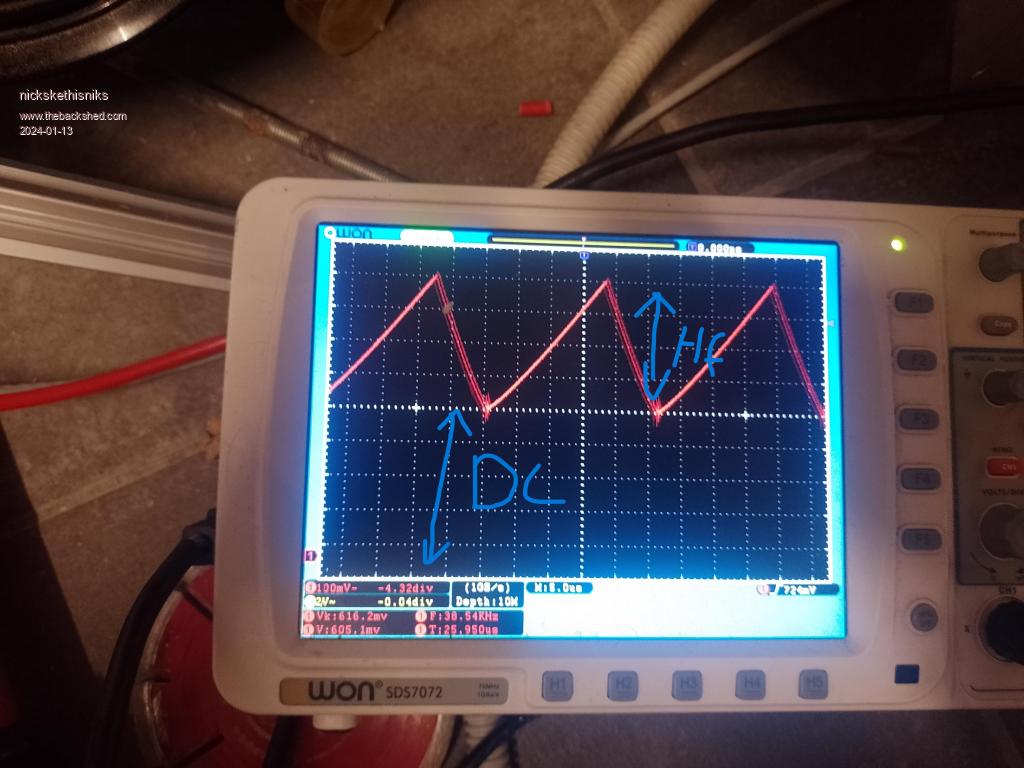 You can get away with solid wires you might think, but when using gapped cores something else gets introduced, "fringing". Fringing . Edited 2024-01-13 05:43 by nickskethisniks |
||||
