
|
|
Forum Index : Electronics : Calibration suggestions invited
| Author | Message | ||||
Dinosaur Guru Joined: 12/08/2011 Location: AustraliaPosts: 304 |
Hi All I have a system that measures the current flowing from/to the battery.(230Ah Lipo4) It measures the current through a hall device and feeds the output voltage into a Voltage to frequency converter.Both devices profess a good linearity. My problem is coming up with a simple yet reliable method to calibrate the current. I have a 2 amp power supply that shows current and 3 different multimeters that all show different values for the same current. The variation being from 10 to 30 mA. I am hoping to calibrate in the 10-15 amp region and can use the battery (13.2 V avg) as the source. I am sure I can find or make a dummy load that will draw that kind of current. Each measurement cycle takes 1 minute. BUT, the voltage will drop as I draw that current for 2 or 3 minutes. The dummy load will heat up and it's resistance will vary. Having spent most of my working life in computerised weighing systems, I really appreciate the simplicity of adding a known weight that doesn't vary. So what is my best option for simulating this scenario with current ? Regards Hervey Bay Qld. |
||||
| wiseguy Guru Joined: 21/06/2018 Location: AustraliaPosts: 995 |
Hi Dino, Does the hall effect device have a central hole or void for the wire to pass through ? If it does, using relatively thin wire that can pass one amp you can wind 20 turns through it and passing 1 amp gives a result as for 20A, passing 0.5A gives a result as for 10A with minimal heating. You can use the bench supply instead of using a real battery and a 10A - 20A load. With regard to the meters I think you need to compare their results with another upmarket meter that has had a recent calibration to figure out which ones tell the truth better, then work out the offset or and gain inaccuracy for the other 2 meters and write a sticker on the back with their correction factors. The alternative is to find an accurate resistor (at least 1%) of say 10 ohms, set a power supply to 12V (that at least 2 meters agree with). The current drawn by the resistor through the measuring meter should be 1.2A. Nice part of the world you have there, recently spent some time at the Urangan Caravan Park by the bowling club. If at first you dont succeed, I suggest you avoid sky diving.... Cheers Mike |
||||
| pd-- Senior Member Joined: 11/12/2020 Location: AustraliaPosts: 122 |
A current shunt https://au.element14.com/murata-power-solutions/3020-01098-0/shunt-50mv-20a/dp/1339338 0.25% accuracy for $42 is ok |
||||
| Dinosaur Guru Joined: 12/08/2011 Location: AustraliaPosts: 304 |
Hi All Mike , unfortunately my sensor is on a board See pic I do have a milliOhm meter to measure resistance accurately, so getting the value of a load won't be a problem. Maybe a toroidal tranformer or choke (out of a blown Inverter) may have the right value. The voltage really does not matter, as long as the current is known, which measuring with a milli volt capable meter should reveal. PS: Agree about my part of the world, we live overlooking the Pialba CP and always enjoy a breeze even on humid days like at the moment. @pd-- The shunt I had thought about, but still need a stable load. Regards Hervey Bay Qld. |
||||
| Godoh Guru Joined: 26/09/2020 Location: AustraliaPosts: 378 |
Hi Dino, could you just use a car battery to supply the power, it should not drop that fast? Then maybe as you are only using 12 volts DC you could drop your resistor into a large bucket of water, that should help cool it to prevent the resistance changing too much. Good luck Pete |
||||
| Dinosaur Guru Joined: 12/08/2011 Location: AustraliaPosts: 304 |
Hi All That is a clever idea,although I will already be using my Lithium camper battery. I guess if the water starts boiling , I got it wrong  Regards Hervey Bay Qld. |
||||
| SimpleSafeName Senior Member Joined: 28/07/2019 Location: United StatesPosts: 286 |
How about one of these? https://www.amazon.com/Electronic-Interface-Adjustable-Intelligent-Temperature/dp/B07HB3XK7L |
||||
| Dinosaur Guru Joined: 12/08/2011 Location: AustraliaPosts: 304 |
Hi All Good find. I can put up with not showing mV (hopefully it rounds correctly) BUT, unlike you guys in the US, I can't get delivery before 19th March. Amazon is basically a storefront for overseas suppliers. Regards Hervey Bay Qld. |
||||
| SimpleSafeName Senior Member Joined: 28/07/2019 Location: United StatesPosts: 286 |
Well, I only used the Amazon reference to avoid what comes next: https://www.aliexpress.us/item/3256801526609441.html?spm=a2g0o.productlist.main.21.355731086m5T3M&algo_pvid=a670149d-f8a2-4053-a06f-c912fede6faf&algo_exp_id=a670149d-f8a2-4053-a06f-c912fede6faf-10&pdp_npi=4%40dis%21USD%2141.21%2132.97%21%21%2141.21%2132.97%21%402101e9d317057974399917793e54de%2112000017257595171%21sea%21US%21167087857%21&curPageLogUid=hXt3L3mR401W&utparam-url=scene%3Asearch%7Cquery_from%3A I had intended to leave finding the best deal vs availability up to you. :) Estimated delivery (to me) is Feb 08. Which is looking pretty attractive at the moment given that the mail hasn't run in a week due to snow... |
||||
| phil99 Guru Joined: 11/02/2018 Location: AustraliaPosts: 1783 |
The link works just as well if you only use the bit up to .html. The rest is specific to your search and location etc. https://www.aliexpress.us/item/3256801526609441.html |
||||
| SimpleSafeName Senior Member Joined: 28/07/2019 Location: United StatesPosts: 286 |
Good to know, I'll keep that in mind. Thanks! |
||||
| Dinosaur Guru Joined: 12/08/2011 Location: AustraliaPosts: 304 |
Hi All Before going down the path of using a dummy load, I thought I would hook up the cro and see what the Switched Mode PS was producing on the 5vdc rail. Even though I am getting a stability of about 4mA , I suspect it is because the spikes on the 5v rail are being averaged in my 60 sec readings.Although there is an occasional high positive spike. Adding a cap to the PS output didn't affect it hardly at all. Coincidentally I read this article this article this morning on Hackaday. The switching regulators I am using are from JayCar and can be seen here . There is no spec advertised other then Amperage. My question is: Are these spikes caused by the Pico pulling on the 5v rail, or by poor choke design on this step down converter.? I would have expected a more symmetrical noise if it was the step down converter. Worth noting that I have tested this on a 13.3 v DC supply as well as a 12vdc wall wart. My load current during this test was 40mA on the 12vdc. 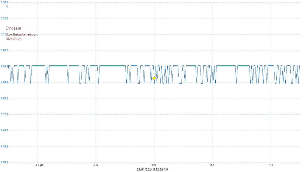 I have observed the same waveform on my PicoScope 2000 and on an older crt cro.(can't remember the name,workshop is a 5 min walk away) with different probes at 1:1 and 10:1. Regards Hervey Bay Qld. |
||||
