
|
|
Forum Index : Electronics : EMI radiated by my inverter - how to reduce
| Author | Message | ||||
| poida Guru Joined: 02/02/2017 Location: AustraliaPosts: 1388 |
Lately I've been playing with my toy spectrum analyser which is just a STM32F4xx based microcontroller. It delivers very good signal to noise performance, nearly as good as the theoretical from it's 12 bit ADC. When testing and developing the code at work, I get great results. But when I run it at home, with the inverter powering the house, it's gone bad. The EMI emitted from the inverter takes away all the fun. results after the changes (discussed below) can be seen here 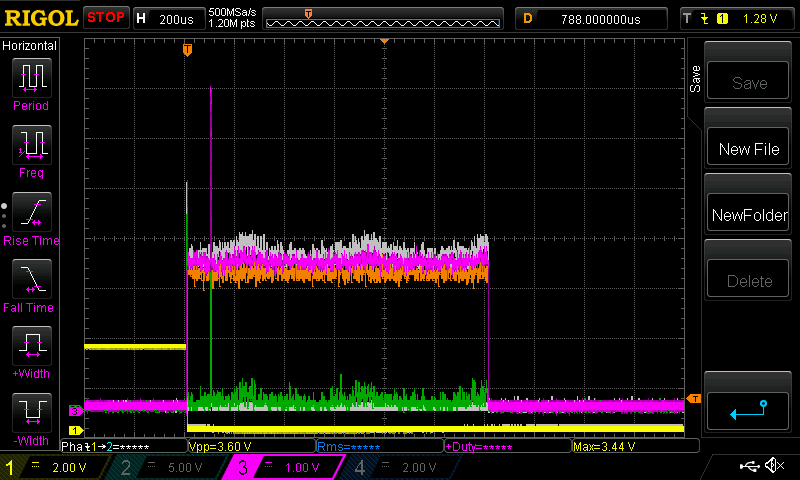 The White trace is before mods Orange is house running on street power, sort of the best I could get Purple is after the mods. The Green trace is the same as the White trace but with 10dbV/division Vertical scale is 20 dbV, and the peak is a 1V p/p sine wave at 2kHz 20dbV is the same as a factor or 10 change in voltage. So the noise is about 60db down from the signal. 60db down is 1/1000th of the voltage. The scan width is 0 to 25kHz over those 6 divisions So it appears I "halved" the EMI since the purple trace is about in the middle of the other two. It might only be 1/3 less due to the log scale but it's worthwhile to get. The inverter is a Madness power board with 4 x 4 FETs, a 70uH choke and a 3kW Toroid. The choke is located on one of the primary winding ouputs of the power board. That gave me the White trace. I change the choke into 2 x 30uH chokes and put one on each of the primary winding outputs. This gave me the Purple trace. I then put a mains filter (as found in a 3kW Aerosharp. I used the biggest one.) but it did very little to the noise level. If you do this, your results might vary and in fact see it helps significantly. All the inverter components are inside a metal enclosure. I have two clip on ferrite chokes on the 240V output cable and these are about 1 foot outside the box. The above traces are not time averaged. Each is the result on one scan only. Below are traces where I averaged 8 scans, to smooth over the noise variation and give a clear indication of the average noise level. I chose different scan settings 0 to 2,500Hz 1024 frequency bins and average 8 scans This is with the inverter off: 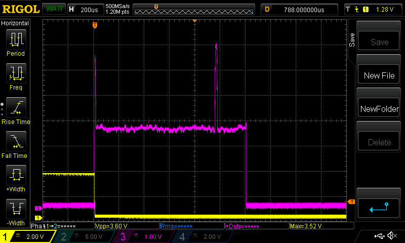 and with it on using the modified design 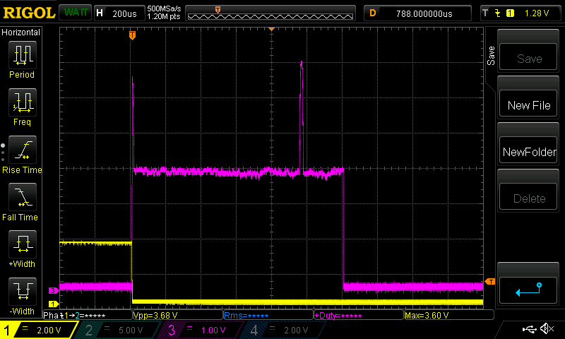 This is not bad at all. I want to compare this with the clean power/room I enjoy at work, to see what is possible here at home. The board looks like this: 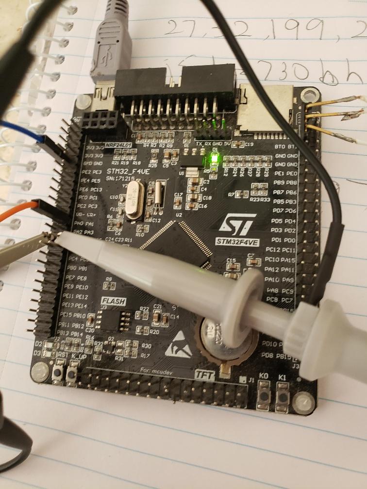 The code permits: sample sizes from 256 to 4096 time averaging of the trace 8 and 32 scans sample rates from 200Hz to 500kHz, resulting is FFT widths of 100 to 250kHz sample averaging from 1 to 64 samples per recorded data sample (v. good to kill noise) Linear, 10dbV/division and 20dbV/division vertical scale A range of windows to choose from, I usually use "Flat Top" see here to learn what window functions do According to FFT theory, you can expect a better or worse noise floor when you change the sample size and or sample averaging. Also, the ADC introduces more or less noise as you change the ADC frequency and sample and hold timing. I can see the effects of this, when playing and learning about signal theory in the clean power of my work office. I found this project very enjoyable and educational. here is the code, if anyone is interested. You change the various parameters of the FFT and sampling via a serial port eg "s5" means sample at 5000Hz stm32f4_cmsis_fft_serial_config.zip Edited 2024-01-21 10:20 by poida wronger than a phone book full of wrong phone numbers |
||||
| KeepIS Guru Joined: 13/10/2014 Location: AustraliaPosts: 1358 |
Seriously that is really nice: Another nice project to play with, I'm not sure I'll live long enough to try them all. A while back I carried out some testing with a HIOKI AC line analyzer, I found very little difference in Inverter AC harmonic content with various AC filtering methods. It was quite good even with a basic filter. I think the only advantage the Mains had was the lower impedance or current sink capability from crap loads causing a DC component into the AC line. It's all too hard. Mike. |
||||
