
|
|
Forum Index : Electronics : 2x12V non dissipative battery balancer
| Author | Message | ||||
| less_is_more Newbie Joined: 03/04/2023 Location: SpainPosts: 12 |
Hi all, opening this thread coming from https://www.thebackshed.com/forum/ViewTopic.php?TID=16348&P=2#215882 This non dissipative battery balancer is based on a concept I didn't find to be used anywhere: just take a 50% duty cycle DC-DC, and you generate the perfect V - V/2 ratio  . .start the DC-DC and it will charge the battery with less voltage, be it the high side or the low side one. It is always balancing, so it is nor a top nor a down balancing. Looking for a ready to use power board, I found this on ali: 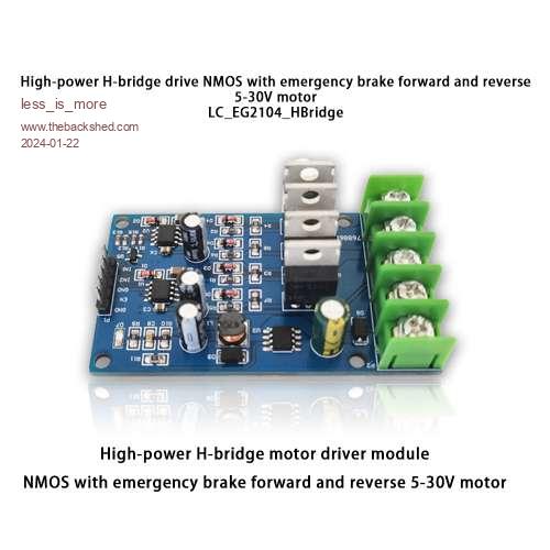 It has 2 half bridges with 3205 mosfets (80A max), and their respective 2104 drivers, a switching input for each half bridge, and a common enable input. Also found on the board is a XL7005 switching regulator, which outputs 12V for the 2104 drivers. Cost of the board was less than 10€ with shipping. Only one half bridge would have been sufficient BUT has a very high current ripple. Two half bridges driven at 180º phase difference reduce this ripple dramatically. Furthermore, if the inductors of the 2 half bridges are coupled, you can decrease their size. Here we use a SMPS common mode choke which is easy to find or recycle from a broken PC supply, it has to be used in differential mode. Of course, the current will strongly depend on the battery unbalance, as well as on the circuit and battery resistance. To not destroy the switches (mosfets) by overcurrent, some sort of current control has to be implemented. Starting/stopping the DC/DC is sufficient and very simple, there is no need for duty cycle correction whatsoever. With a current value estimate: - you can stop if the current becomes too high (>Imax), for example when the batteries voltage are too different. This will protect the mosfets. - you can also stop if the balancing current stays very low (<Imin), in order to reduce the balancer's current consumption. This will happen when the batteries are almost balanced. Now to the current sensor. I wanted something simple, with a low current supply: a current transformer fulfills perfectly these needs, and is low cost. But how do you sense a DC current with a current transformer which can only read AC  A current transformer reads not only AC, it will read every CHANGE in the current. So lets us change the current with our control! It is as simple as periodically stopping the current during sufficient time (until it decreased to zero), restart it and read how it is increasing. To generate the 50% duty cycle and realize the current control, I choosed the simplest microcontroller usable with Arduino IDE. This is the cheap 8 pin Attiny13, which has only 1k program space, and 6 usable I/O pins if you include the reset pin. This is enough for - 2 complementary driver signals for every half bridge - enable/shutdown the drivers - read the current and its direction - have a led showing some information (charging or not, overcurrent, which direction,...) I ended finally with this simplified schematic  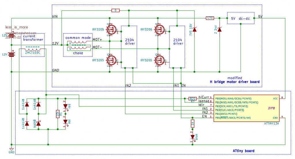 There are only 11 components on the additional attiny board, including the microcontroller. - 4 diodes to rectify the current transformer signal, one of them is a shottky, put on the direction signal to avoid it to dive below -0.5V - 2 resistors as current transformer burden. 10k to set the starting (Imin) level, the other one which can be disconnected sets the overcurrent shutdown (Imax) level. - Parallel to the fixed burden are 2 red leds in serie, this limits the voltage value below the attiny Vcc=5V, but let the signal grow above the 0.6*Vcc= 3V to be able to detect a high level. - A blue led and its limiting resistor are tied on the ENable output. This shows charging, direction is given by the blinking sequence. Footnote added 2024-01-23 22:06 by less_is_more To be corrected on the circuit:  Zener diode on the 5V dc-dc is not 24V, but 36V |
||||
| less_is_more Newbie Joined: 03/04/2023 Location: SpainPosts: 12 |
This is the resulting prototype. 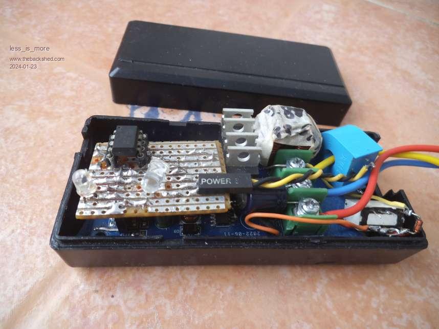 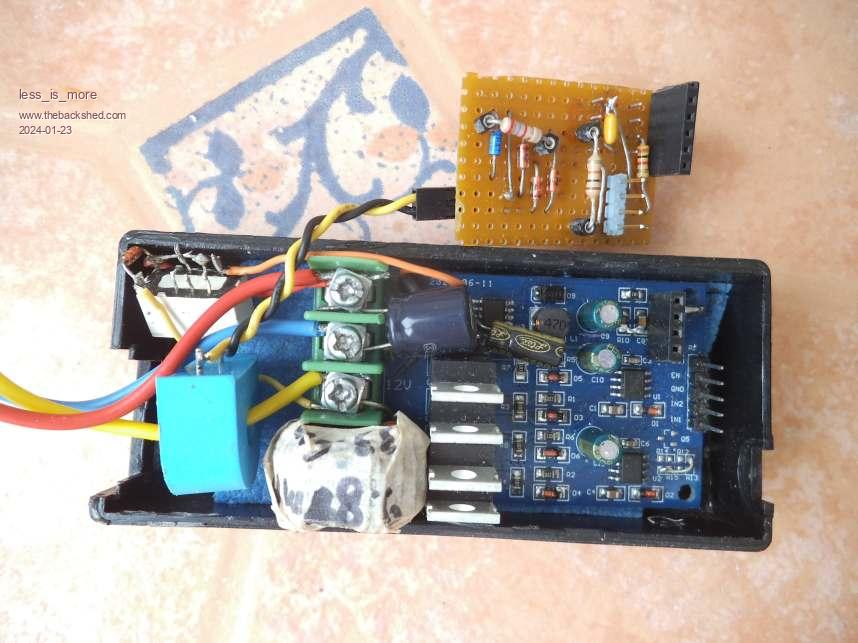 It all holds in a 100*40*30mm volume. The plastic box is from a dead adaptator. A little relay between 12V-24V has been added here, only for use on the car: this cuts the XL7005 supply when contact is off, shutting totally down the balancer. The powerboard has been a bit modified: 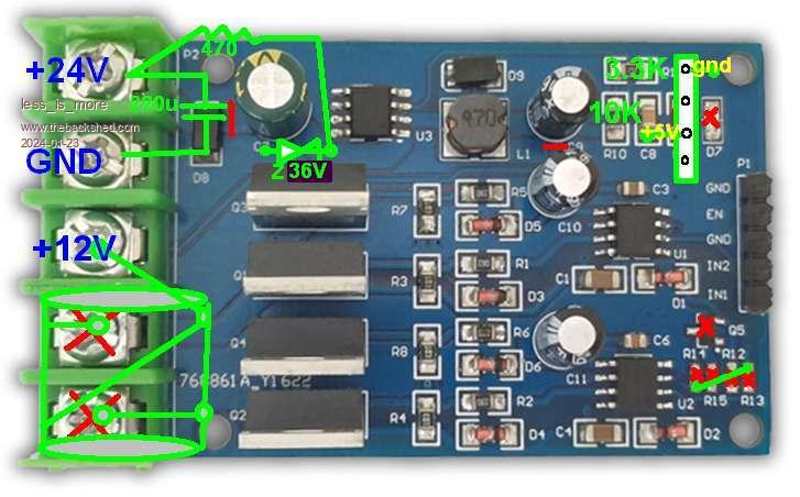 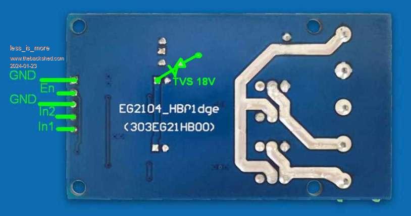 - a PNP transistor inverting the ENable signal and its resistors have been stripped to permit direct access to the 2104 shutdown pins. - the 12V switching regulator has been modified to output 5V, its LED unsoldered to reduce consumption. - the 2104 chips are now driven directly from the low side 12V battery. - the MOT+ and MOT- screw PCB connectors are replaced by the common mode choke connected in differential mode to the 12V connector measured choke inductance is: 8mH , 33uH leakage - added TVS/Zener protections on the 2104 driver supply and XL7005 supply - added connector on the XL7005 unit to pass the 5V supply onto the attiny board - added 220uF capacitor on 24V The control board is realized on a stripboard which holds on 2 powerboard connectors. Another little plug brings the current transformer signal. The attiny has to be DIP8 on a socket. You need to remove it for programming, to do on a HVSP programmer because the reset pin is also used. (the programmer can be made with a nano on a breadboard with few components) This mounting did'nt give any problem mounted on the car, but is well maintained in the box. |
||||
| less_is_more Newbie Joined: 03/04/2023 Location: SpainPosts: 12 |
Some measures I did on the modified board: - power circuit alone (not board): choke, mosfets and their drivers, drivers supplied from low battery 12V when the control board is disconnected, the EN pin not connected or in shutdown mode (EN=0): no switching at all, I am not able to measure supply current (<1uA) on the 12V or 24V lines. - 5V power supply with XL7005 DC-DC alone. Quiescent current 2.4mA @ 24V. It is not the most efficient one, and limited to 0.4A. Good thing: it is already on the power board. I plan to replace it with a MP4560 board, which is much more efficient and could also be used for USB charging (2A max) Measures on the control board (5V supply) - switching, without sleeping: 6.2mA @ 5V - same with sleeping (IDLE) between switches: 4.9mA @ 5V - no switching at all, and sleeping (PWR_DWN): 25uA @ 5V (waiting to restart switching) Measures on the actual complete circuit: - only connected to 12V (switching and generating 24V but no current) : 25mA @ 12V - only connected to 24V (switching and generating 12V but no current) : 13mA @ 28V (not easy to measure because the firmware won't keep switching with such low current). |
||||
| wiseguy Guru Joined: 21/06/2018 Location: AustraliaPosts: 995 |
Thanks for the post and description, I like lateral thinking being applied to things to exploit their capability. At the beginning of your first post you said it was intended to balance charge between 2 x 12V batteries in your car. So you have a 24V car ? or you put the 2 x batteries in series just to balance them ? or there is a way of connecting this balancer to balance 2 batteries with a common negative ground ? What current range can you measure with the 10K burden resistor on the current transformer before it changes range and uses the 820R load resistor and what is its max current range ? Are the 2 x Red LEDs across the bridge rectifier to act as a zener to limit voltage to the tiny or to indicate high power transfer or to clip voltage transients on the 10K range ? Sorry for all the questions.... If at first you dont succeed, I suggest you avoid sky diving.... Cheers Mike |
||||
| less_is_more Newbie Joined: 03/04/2023 Location: SpainPosts: 12 |
YES (but not an electric one!  Just a 44 year old LandCruiser, running mostly with recycled vegoil) Just a 44 year old LandCruiser, running mostly with recycled vegoil)I don't measure anything, just looking if digital input changes to high state (like a comparator). With the 1000:1 current transformer and high state voltage reached at 3V, 10k burden gives 0.3A , and 820//10k gives 4A. Consider these numbers as estimates. You're right once more, act as a zener (and clipping voltage) was the most important, high power transfer visualization was second, but is finally not of much use with the firmware algoritm. More on that when I'll explain the firmware. |
||||
| less_is_more Newbie Joined: 03/04/2023 Location: SpainPosts: 12 |
First of all, I found some more errors in the circuit, here is the corrected one: balancer_circuit_V1.pdf Firmware Switching frecuency is 31kHz, toggling IN1 and IN2 at 62kHz is done by timer interrupt. Because of the use of a current transformer which can only see current variations, switching has to be stopped periodically, untill the current extinguishes. This can be done waiting sufficient time with NO switching (125-250msec for our needs). When we then start switching, the current will begin to rise, depending on battery voltage difference and the current path resistance. So will too the current in CT's secundary, and a voltage will build up in the CT burden resistance. At the beginning, we look for Imin (high CT burden resistance) In the case Imin is reached, connect immediately the low CT burden resistance so as to detect Imax. In any case, if Imax (overcurrent) is detected, stop immediately switching for 4sec, then return to initial state These detections must be quick, so they are done in interrupts. As our blue led (actually switching) is the only mean to know how batteries are charging, we use different start/stop sequences to give this info. Starting from initial state (stopped since at least 125msec), we have: Sequence in normal conditions (Imin reached, Imax not seen). Two cases depending on charging direction: - if charging low side battery: switch1 4sec, stop 250msec (LED on + every ~4sec: short off) - if charging high side battery: switch1 4sec, stop 125msec, switch2 64msec, stop 125msec (LED on + every ~4sec: short off, short blink, short off) Sequence when Imin is not reached at the end of switching period switch1: (LED off + every 8sec: short blink) - switch1 64msec - stop 8sec Sequence when Imax is detected, normally very soon after starting switching, response to stop is so quick that you hardly see the blue and red LEDS light up. (LEDs off + every 4sec: very short blink) To reduce current draw, most is done by interrupts (watchdog timer for sequence times, timer for switching, pinchange or INT0 for current detection). The microcontroller is essentially sleeping (idle during switching, power down when switching stopped), and wakes up for every task . The whole firmware takes less than 600 bytes. Here is the actual one, subject to possible changes in the future. The only problem which remains, is that the charging direction is not always well detected with lower currents: with higher Imax (lower R2 value ), the current above which direction is correctly detected becomes also higher. This problem does'nt affect the balancing, only the display sequence. As I have no clue why this occurs,  R2 has been defined by trying different values. R2 has been defined by trying different values. Wellcoming here any proposal to resolve this issue |
||||
| less_is_more Newbie Joined: 03/04/2023 Location: SpainPosts: 12 |
To program the attiny whith the firmware, as all 6 I/O pins are used -including the reset pin-, you will need a special HVSP board (High Voltage Serial Programmer). You can use this one I shared in the Microcontrollers and PC projects forum. It was developped for my first attiny project, a load detector able to start/stop an offline inverter, which will be described in another thread. Edited 2024-01-30 21:48 by less_is_more |
||||
