
|
|
Forum Index : Electronics : CNC Router on USB
| Page 1 of 2 |
|||||
| Author | Message | ||||
| vasi Guru Joined: 23/03/2007 Location: RomaniaPosts: 1697 |
Hi guys, I finally found an easy and efficient solution for having a CNC Router connected to USB without spending a fortune. I found recently UBW boards, based on PIC18F2550 (and USB-CDC - virtual comm. port) with a very efficient firmware. The C version of (older) firmware receive a byte from USB and then "post" it to port B of microcontroller, simulating the Parallel port. All you have to do is to make a program in Basic which interpret G-Code and send bytes on serial port. Or better, download CNCPro from here and look for the routine where bytes are send to parallel port and make it serial. I advice you to have only one USB device on your computer and that being your board (or don't move your mouse  ) to let USB bus free. ) to let USB bus free.
In time, you can switch at D version of the firmware, which have a command system implemented and a back response (OK) from your board when received your string without errors. Or, we can advance at a version where G-Code is interpreted inside microcontroller. The firmware can be used also on my board, via a shield. And important for me, the firmware can be also in JAL language. Both boards use a bootloader for easy updates on firmware. Playing with such a system (or idea), can be fun. --------------- Edit: Sparkfun have a very nice UBW board but at $24,95 can be expensive. You decide. It come with firmware D version but once you buy it, you can upload any kind of program you want. Is suitable also for loggers. 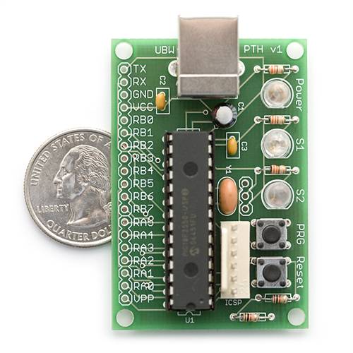
Hobbit name: Togo Toadfoot of Frogmorton Elvish name: Mablung Miriel Beyound Arduino Lang |
||||
| vasi Guru Joined: 23/03/2007 Location: RomaniaPosts: 1697 |
I started the development of an USB CNC Router using FreeJALduino board. Right now using leds instead of stepper coils and switches for Emergency stop and limits reached. What I'm trying to obtain. A host software which will interpret GCode source and then send strings to CNC board via USB. Something like this: "X2000y3000Z0" And means how many steps on XYZ axis, and in what direction (e.g., X=left and x=right) And then, host software waiting for "OK" signal from board to send another string. Of course, program will send also settings about speed before and for each string. The challenge is to find an algorithm to not lose USB connection.... Because steppers are connected directly to the board, and host software send "sets" of steps, you can achieve this also with a 28 pin PICAXE chip which can have a hardware UART and can do maximum 115200 bps (can be smaller without problems). Via serial port, of course if you don't want USB comm. This is the link to the page: http://sites.google.com/site/funlw65/tutorials/freejalduino- with-jallib/usb-cdc---xyz-cnc-router-board And this is a little movie on youtube (Do not laugh of my voice): http://www.youtube.com/watch?v=B5_6C535KWU Vasi Hobbit name: Togo Toadfoot of Frogmorton Elvish name: Mablung Miriel Beyound Arduino Lang |
||||
| Gizmo Admin Group Joined: 05/06/2004 Location: AustraliaPosts: 5019 |
So thats what you sound like 
Good work Vasi. Have you seen the MaxStepper by Kellyware http://www.kellyware.com/. It works with KCam, which I've used on my cnc router. I did like KCam, but by default it uses the parallel port and running under Windows that was too slow. MaxStepper was the fix, but I ended up using EMC2 under Unbuntu, it ran much smoother but was not as user friendly as KCam under Windows. Glenn The best time to plant a tree was twenty years ago, the second best time is right now. JAQ |
||||
| vasi Guru Joined: 23/03/2007 Location: RomaniaPosts: 1697 |
Thank you Glenn, I never seen before, is a nice board. The advantage is serial connection which can be kept continuously active without any action from host or client. With USB is a little harder to keep it alive, you must "push" it constantly. Also, I don't know what is the minimum time to keep a coil energized to be sure that magnet from rotor is attracted. Is this specified in a stylesheet which come with the stepper? Vasi Hobbit name: Togo Toadfoot of Frogmorton Elvish name: Mablung Miriel Beyound Arduino Lang |
||||
| GWatPE Senior Member Joined: 01/09/2006 Location: AustraliaPosts: 2127 |
Hi vasi, I have a new USB-SER converter, and I have seen the USB problem you mention. If there is no PC program looking for COMM's, then the USB port powers down. I think this may be configurable with PC power saving features. The port wakes up and re-establishes COMM's when the PC application is run. I use this adapter for testing my SER COMM loggers. The port shutting down does overcome problems I had with the external COMM data being interpreted by the PC as mouse movement when the data logging application was not running. COMM activity lights make the problem solving so much easier as well. Gordon. become more energy aware |
||||
| vasi Guru Joined: 23/03/2007 Location: RomaniaPosts: 1697 |
Thank you Gordon, I will look at power saving settings on PC. Apart of that, I think the FTDI chip is keeping the USB connection alive. In USB Serial library I have "usb_serial_flush()" function (JAL language) which must be called often. If I have blocking delays , connection is lost. What I must do is to combine this with any timing required for different speeds of the steppers. But first, is to find out what is the biggest delay without loosing USB connection... Until now, at 2 seconds delay (having in mind also counting pulses on a windmill - but for this I have solutions already), connection is dead. More tests... With Pinguino IDE (which use SDCC compiler and gpasm) of Jean-Pierre Mandon I had no problems but is using another type of USB connection, where you can't use old applications connected to serial comm. (again, having in mind windmill loggers) so, you need to write a new application using "libusb". Is a bulk type of connection at 2MB/s speed... Vasi Hobbit name: Togo Toadfoot of Frogmorton Elvish name: Mablung Miriel Beyound Arduino Lang |
||||
Downwind Guru Joined: 09/09/2009 Location: AustraliaPosts: 2333 |
Hi Vasi, I had a look at the utube video, and no i didnt laugh. One thing that came to mind from watching is you are using a laptop. Now you might well know more about this than me, but i know other software i looked at for running my cnc router clearly stated it could not be used with a laptop because of the power saving feature shutting down the port. Be interesting to see if the problem you have existed on a standard pc. Good luck. Pete. Sometimes it just works |
||||
| GWatPE Senior Member Joined: 01/09/2006 Location: AustraliaPosts: 2127 |
Hi Pete, I only use laptops as GP computers for programming and internet. It is a simple task to turn OFF the power saving aspects. I only power save the screen. My Intel Atom board used for logging my house is running as a headless server directly powered from the 24V main RE battery. There are some great ATX socket power supplies available these days. BTW, before I got the Atom board, I used a laptop and a miniPC for data logging. These computers ran for weeks without power saving, and I did not lose any data in the logging process. My Atom board has been running now for over a month. I do intend rebooting it a few times a year, just to allow windows to get a clean start. The few hours a CNC machine operated should not present many problems once the power saving aspects were disabled, even on a laptop. Gordon. become more energy aware |
||||
| Downwind Guru Joined: 09/09/2009 Location: AustraliaPosts: 2333 |
Handy to know Gordon, as would like to run the cnc from a laptop when i get my paws on a suitable castaway. For a small router the pc is almost as big as the machine at present. (but cheap) I dont guess the parallel port is effected with power saving any different than the other ports?? Pete. Sometimes it just works |
||||
| vasi Guru Joined: 23/03/2007 Location: RomaniaPosts: 1697 |
Hi Glenn, You can tell me how many full steps are needed to travel on entire length of x axis on your CNC Router? I want to see if my approach is going in right direction... Thank you! Vasi Hobbit name: Togo Toadfoot of Frogmorton Elvish name: Mablung Miriel Beyound Arduino Lang |
||||
Bryan1 Guru Joined: 22/02/2006 Location: AustraliaPosts: 1210 |
G'day Vasi, Just to give you an idea of the steps needed, on my first cnc attempt using heavyduty draw slides which I've now canned as there was about 0.015" backlash or rocking at the top of the proposed Y axis height. I used a 10 TPI acme screw which I screwcut pretty accurate as I do have a 1/2" x 10 TPI acme tap here. Going thru a 2.4:1 chain drive reduction I needed 2456 steps for 1 revolution which is only 0.1". It took ages in Kcam to get the x-axis true to 0.001" over 13". As far as trying to use 1 pic micro to do the number crunching from the PC and do the number crunching for the cnc a dspic or pic32 would be needed. Instead use a 18f2550 or other USB chip to decode the pc side of things, then send the data to another slave pic to drive the steppers etc. The Oshonsoft Basic compiler for the 18f does have the USB routines to easily make a HID USB device to read the data from the PC. In the spare time between USB calls the master pic (USB pic) could send the stepper data to say a slave pic for each axis. So say X2.503 Y 1.236 Z 0.05 the master pic could send via I2C or SPI or even bit bang the X,Y,Z data to each slave pic to decode the amount of PWM needed to move each axis as needed. Each axis slave pic could also incorporate the limit stops, home switch etc then as the code in each slave is being done send via I2C etc to a host pic for the digital readout for the axis's. Some guys on the CNC forum have tried to use a pic for CNC and I do need to check there progress as I aint looked in ages. As you can see this aint a small task but if done and done correctly you even just load the G-code data to a SD card and have a cnc PC'less. Now that would be a unique machine to own. Cheers Bryan |
||||
| Downwind Guru Joined: 09/09/2009 Location: AustraliaPosts: 2333 |
Hi Vasi, There is a Pic-cnc group here in Adelaide if you would like some information i can track them down and pass on an email address or what ever contact they have. In my small cnc machine i used 1.5mm pitch 10mm dia allthread and the motors are 200 step per rev. Running the driver board in 1/4 step mode i have a calibration setting of 534 steps per mm. This is accurate enough to drill pcb's. Unless you are intending on running big motors i would not bother to build the driver board and buy one off ebay as mine costed $90.00 (Au) for a 4 axis driver board and when i added up the cost of parts i could not build it for that. My board has a direction pin and a step pin for each driver, so you would only need to fire out a direction command and a step command to each axis driver for each step. I had thought about a pic or usb driver for cnc to, but after operating the machine for a while i thing it would not be so practical as i find i am constantly needing to use the screen to make changes to programs and machine operations and functions. A dedicated processor/driver would be good if you were making something like cupboard doors in high numbers and it fitted into a nice gig that you hit the go button and it routed it time after time. But for one offs and the odd tinkering project i think the need for a screen and changes made mid operation is almost a requirement. All said i am still interested in your project. Pete. Sometimes it just works |
||||
| vasi Guru Joined: 23/03/2007 Location: RomaniaPosts: 1697 |
Thank you for your responses guys, About stepping: For the first trial, I wanted to avoid floating point operations and g-code interpretation (bresenham algorithm, etc.). The serial comm. is made at 115,200 bps (the PC application will see USB as a virtual comm., no need of USB libraries on that part), the board is running at 48MHz (inside, outside is using a 20MHz crystal) and that is 12MIPS. So the board is fast. Also wanted to avoid the complications on "step/direction pulses" approach hoping that this way will be no lost steps So I left all g-code interpretations to PC host application (also, all setup required for a particular CNC). The board is able to handle 4,294,967,295 steps on each axis at once (I hoped that will be enough for full and half steps - depend on the CNC table length): X4294967295Y4294967295Z4294967295/ - this will be the string sent by the PC host application. As I said, direction is determined by the letter (X - for one direction, x - for the other direction) If more steps are required, then the PC application must handle that... About the speed: I have no data about the technical aspects of the stepper. By example, what is the minimum time required for a coil to stay excited to be sure that the magnet of the rotor is fully aligned with it? Say 3 microseconds? That will be the maximum speed for that stepper and for CNC. Anyway, I have two types of delays at hand: for microseconds and for milliseconds, each accepting parameter numbers from 1 to 65,535 (these are language limitations of compiler I use now). Microseconds is first. So, if you need microseconds delays, you will send a number (as string) between 1 and 65,535. If you need milliseconds, for example 1 millisecond, then you must send the number (as string, of course) 65,536 and the board will do this operation: 65,536 - 65,535 = 1 millisecond. Of course, 1000 microseconds equal 1 milliseconds, but this is how board know when to use milliseconds instead of microseconds type delay. In reality, if you need to delay 1 millisecond, you will do 1000 microseconds. Pseudocode: [code] if number < 65536 then DelayUS(number) else DelayMS(number - 65535) endif [/code] This is how I solve delays between steps without having any other information... The string which set the speed will be like this: 65535/ or 131070/ - which means 65535 milliseconds, aberrant of course but this is how algorithm works and will be no limitations or bottle necks inside firmware. Say you give to friends pre-programmed chips because they don't have a programmer or you sell to others... For Home CNC Routing, I think this is enough, and have the advantage to work on USB. If this project is finished well, then no more expensive USB equipment... i think... Is something which any body can DIY. Hobbit name: Togo Toadfoot of Frogmorton Elvish name: Mablung Miriel Beyound Arduino Lang |
||||
| vasi Guru Joined: 23/03/2007 Location: RomaniaPosts: 1697 |
And of course, those strings can be recorded on a 2Gb SD card and that will be more simple... But that mean another board. Can be a single board with both features, or only with SD card (but both will require the 18F4550 40pin chip, the big brother of 18F2550)... Vasi Hobbit name: Togo Toadfoot of Frogmorton Elvish name: Mablung Miriel Beyound Arduino Lang |
||||
| Downwind Guru Joined: 09/09/2009 Location: AustraliaPosts: 2333 |
Vasi, Guess you wish to build your own sd or usb interface but have you had a look at these boards for off the shelf. SD & USB Boards One of the boards available will handle both sd & usb. Why the 18F2550 as there is a link elsewhere here on a sd card circuit using the 16F819. Pete. Sometimes it just works |
||||
| vasi Guru Joined: 23/03/2007 Location: RomaniaPosts: 1697 |
Well, first, it must be 18F chips because we have bigger speed and memory and you can use a full featured language (At $2 difference for the price you spend for 16F's). Then, 18F2550/4550 have a native 2.0 USB engine inside. I already made a development board based on 18F2550 having in mind the "future" of serial and parallel ports... And not the last, because of DIY phenomena... I have grown on this forum, guided by the "rules" of this community, rules which I used on other forums as well. 16F819 features: [code] Program Memory Type Flash Program Memory (KB) 3.5 CPU Speed (MIPS) 5 RAM Bytes 256 Data EEPROM (bytes) 256 Digital Communication Peripherals 1-SSP(SPI/I2C) Capture/Compare/PWM Peripherals 1 CCP Timers 2 x 8-bit, 1 x 16-bit ADC 5 ch, 10-bit Pin Count 18 [/code] 18F2550 features: [code] Program Memory Type Flash Program Memory (KB) 32 CPU Speed (MIPS) 12 RAM Bytes 2,048 Data EEPROM (bytes) 256 Digital Communication Peripherals 1-A/E/USART, 1-MSSP(SPI/I2C) Capture/Compare/PWM Peripherals 2 CCP Timers 1 x 8-bit, 3 x 16-bit ADC 10 ch, 10-bit Comparators 2 USB (ch, speed, compliance) 1, Full Speed, USB 2.0 Pin Count 28 [/code] My firmware is already over 16F819 memory storage capacity. The board drive steppers directly so eliminate the need of another three stepper boards. For USB link, a 28pin is enough. But having a SD card and still driving the steppers directly, you need a 40pin chip (with or without USB feature - at your choice) Hobbit name: Togo Toadfoot of Frogmorton Elvish name: Mablung Miriel Beyound Arduino Lang |
||||
| Downwind Guru Joined: 09/09/2009 Location: AustraliaPosts: 2333 |
That explains it pretty well what you are doing. I misunderstood and thought you were using several pics. What sort of H bridge are you going to use. Pete. Sometimes it just works |
||||
| vasi Guru Joined: 23/03/2007 Location: RomaniaPosts: 1697 |
Well, unipolar steppers, so connection will be simple... This is the development board: 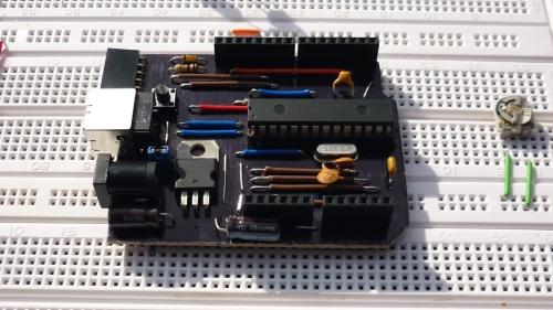
And this is a montage for testing the firmware (step by step): 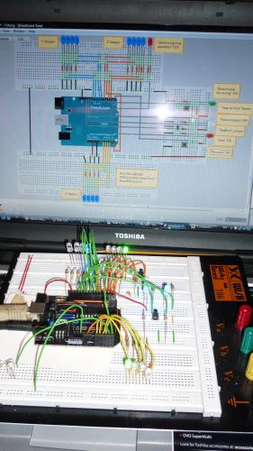
This time I connected all three "stepers", the switch for stop/limit, the switch for resume, led for signaling "cnc under movement", led for signaling the emergency, led simulating the relay for powering the steppers, the jumper for selecting the type of step(half/full), led for signaling "board ready to receive strings via USB" - this was needed because of delay introduced by bootloader but can be eliminated if no USB bootloader is used. The board can be stopped anytime, directly from the board, without loosing steps (because the PC application will not send another string until will receive an "OK" from the board)... say, your neighbor ringing at your door... Hobbit name: Togo Toadfoot of Frogmorton Elvish name: Mablung Miriel Beyound Arduino Lang |
||||
| vasi Guru Joined: 23/03/2007 Location: RomaniaPosts: 1697 |
Yes Bryan, I would like to have this board: http://eflightworks.net/ - the first from their page or this: USB 32-bit Whacker - PIC32MX460 Development Board But only as a hobby. I can't imagine yet such a complex application requiring one of these boards: # PIC32MX460F512L # 32KBytes of RAM # 512KBytes of Flash # 78 usable I/O pins # CPU runs at 80MHz # USB Bootloader For me, starting from 18F2550 is enough. If not (regarding to memory space), then 18F4620 and then, 18F4685. Vasi P.S. I know someone did a serial CNC Router with a single 16F877 with steppers connected directly. Is an open source hardware. He wanted to start a new project based on 18F2550... I can't find the link right now I found it: CNC Milling Machine Hobbit name: Togo Toadfoot of Frogmorton Elvish name: Mablung Miriel Beyound Arduino Lang |
||||
| vasi Guru Joined: 23/03/2007 Location: RomaniaPosts: 1697 |
He he, Big  to all. I'm getting results ... to all. I'm getting results ... 
In fact, the firmware is ready and is working as expected (under my testing montage). Apart of this I have a big reason of joy: - I returned to JAL language and managed to finish the project (I spent some time with other compilers without success). Including that "nasty" procedure, strtodec which convert strings in longwords and the target of having 4,294,967,295 steps simultaneously on each axis is achieved (that 16F877 cnc router had only 255 steps per axis and worked). Of course, not a problem for PC software to scale as required but for medium CNC's, better to have an easy task when you have to build such a software... - Everything is working without loosing USB connection and without the need to change from USB CDC to USB HID. In all cases (router under movement, router paused, etc.). Now, for movement the string format is the same, I didn't changed it. But for the delay between steps I have another format. Let me explain. In Jallib (a set of libraries for JAL) we have a set of delay procedures (subroutines) but only two are useful for this project. In microseconds: - delay_10US(byte) - this one accept parameters as byte (1 - 255) and multiply them with 10 (n * 10us). And in milliseconds: - delay_1ms(word) - accept parameters as words (1 - 65536) (n * 1ms). So, the format for delay string is this: "U255/" (without quotes) which mean we have a maximum of 255 * 10 microseconds as delay if we want, or, "M65535/" (without quotes) which mean we have a maximum of 65535 milliseconds delay (no usable delay in reality but is better to know the limits of firmware). I should introduce here some code protection against range errors... but can be done on PC side. What is doing the firmware? Is waiting in infinite loop to receive following chars: [code] forever loop (these are for manual movement - fine positioning?) "?" - it will show the firmware version "A" - will do one step on X axis to right (you decide which direction is that) "S" - will do one step on Y axis to right "D" - will do one step on Z axis to right(up?) "a" - will do one step on X axis but opposite "s" - will do one step on Y axis but opposite "d" - will do one step on Z axis but opposite (Following cars are normally send by Application but you can do it also from a terminal for testing as I do now) "<" - well, this mean, PC is setting delay data and firmware enter in a loop for receiving a complete string M100/ - when the "/" char is received, firmware will send the string for conversion and set the delay accordingly ">" - this mean, PC is sending data for movement X100Y24500Z34/ - after the "/" terminator, firmware extract the direction and number of steps for every axis and start moving, counting also the delay previously set. (of course, at every cycle, firmware is checking to see if an emergency stop switch was pressed or a limit reached on one of the axis - and this is doing also at every step). end loop [/code] This is all. Simple (only when you finished it). Of course, the project needs to be tested on a real machine, under real situations. Unfortunately, the firmware don't have microstepping (only full/half) but this is an unknown "food" for me yet ... I will update my page soon with the new JAL code. Now I'm  ... The hex file will be also available but is made to be used with FreeJALduino bootloader. Maybe I will do also without the need of having a bootloader if here is a request (no modification on sources required). Anyway, you can compile the firmware from sources... ... The hex file will be also available but is made to be used with FreeJALduino bootloader. Maybe I will do also without the need of having a bootloader if here is a request (no modification on sources required). Anyway, you can compile the firmware from sources...
Vasi Hobbit name: Togo Toadfoot of Frogmorton Elvish name: Mablung Miriel Beyound Arduino Lang |
||||
| Page 1 of 2 |
|||||
