
|
|
Forum Index : Electronics : please help with the tl084 charge control
| Author | Message | ||||
| amaridnai Newbie Joined: 11/05/2010 Location: Posts: 2 |
mr inventor, i want to thank you first for your simple (  not yet to me) tl084 controller. not yet to me) tl084 controller.
please help me with the folloing point.... 1.where should i connect the veriable ps? 2.power led always 0n? 3.high trimpot does nothing. when i connectec the circuit for first time with high trimpot cw and low tp to ccw the green led lit after connecting vps at 15v.when i turn down the high tp to ccw it does nothing. i left the htp to the end cw point. now i turned low tp to cw and dump led lighted. i think there is a big mistake when i soldiered the board can you be more specefic=elaborate with the adjustments in simple english? one more thing what about the different resistor value with different pages through the site(i am a novice  ) )
http://www.thebackshed.com/windmill/articles/TL084-Controlle r.asp page was my guide but i could never found a second 12k as mentioned in the parts list. circuit diagrams are complex to me when i only can copy assemble parts on vero boards. i dont know how to talk polite in english or the topic may be very old or may be in wrong place of post...i need help. thank you. 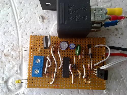
|
||||
Downwind Guru Joined: 09/09/2009 Location: AustraliaPosts: 2333 |
Hi amaridnai, Welcome to the forum. Ahrrrrrrrrrrrrrrrrrrrrrr!!! Excuse me but another problem with this circuit. I have helped a few now and it is always a constuction fault and not a design fault. Lets see if we can help sort your problem out. I commend you on posting some photos along with the question as at least we have something to work with. As for the 12k resistor, the vero board layout is right and there had been some minor changes of late made and am guessing Gizmo forgot to update the parts list when updating the layout design. The last thread that related to a problem with this circuit build is here. http://www.thebackshed.com/windmill/forum1/forum_posts.asp?T ID=2382&PN=2&TPN=1 Page 3 i and others posted some voltage results for each pin of the opamp and you might like to read a bit and do some voltage tests of your pins to give a beter idea of where your problem lies. In the mean time i will try to digest your photos/circuit. Pete. Sometimes it just works |
||||
| Bub73 Senior Member Joined: 10/12/2009 Location: United StatesPosts: 116 |
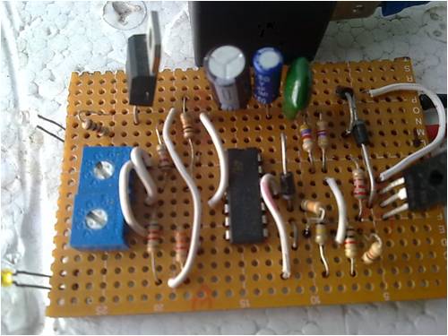
Is the jumper missing between pins 7 & 9 ? Also I like to use a socket for the ic; helps to keep the heat and static off the ic during construction. Will look more later Bob |
||||
| amaridnai Newbie Joined: 11/05/2010 Location: Posts: 2 |
thank you mr.downwind for your response. by saying "i think there is a big mistake when i soldiered the board" on previous post i actually ment to my bord not the published circuit...sorry for my eng. should i post my problems to the link you mentioned?i am waiting for your digestion 
...voltage check?with a multimetre?i dont have a benchtop power supply my own,i took the circuit to a repair shop about 30 min far. i have a old ibm laptop adapter 16v 4.5a will it do for testing? thanka in advance. bub73 thanks for your comment. in the original circuit there is 11 jumpers in my circuit also has 11.in my area no good parts seller so no ic base. may be i should try to make another .as i am unemployed it will take some time..... |
||||
| Bub73 Senior Member Joined: 10/12/2009 Location: United StatesPosts: 116 |
You will need a variable supply to set the high and low pots correctly. I set my high to about 14.6 and the low to 13.0 for a start; when you are finished and have it in your enclosure you can then tweak the settings to your liking. The ic socket isn't necessary, but I found it helps eliminate problems; a used one will do. Read the thread Pete posted a lot of good trouble shooting help there. I'll check back when I can, going to be a busy week end here. Bob |
||||
| Downwind Guru Joined: 09/09/2009 Location: AustraliaPosts: 2333 |
Hi amaridnai Your english is fine, as those that speak it cant always write it correctly anyhow. You have posted your question in the right place so dont stress. You will need some way of adjusting the voltage to set the trimpots up. Your circuit might be working fine as it is, and you just need the right equipment to be able to adjust it. Do you have a few batterys about home that you can add together to increase and decrease the voltage. The batteries can be any size, for example:- 1 x 12v car battery ... this will do to set the low trimpot for a test. 1 x 12 volt battery + 2 x 1.5 volt flashlight batteries in series will give you around 15 volts and should be ok to set the high trimpot for a test. You really need a variable power supply to test it properly now. I would recommend you look to see if you can buy a LM-317 voltage regulator and the few resistors required along with a potometer. The LM-317 is a very common adjustable voltage regulator and very easy to construct on a bit of vero board. You can use this with your laptop adaptor to set any voltage from 1.25 volts to 15 volts with using your laptop adaptor. The LM-317 looks just like the LM-7808 you have, and be well worth the small cost of buying one. Have a look for a circuit diagram for a LM-317 and if you have trouble i wil find one for you. It could be a good idea if we get Gizmo to add one to the list of parts for use with setting the circuit up. Pete. Sometimes it just works |
||||
| Gizmo Admin Group Joined: 05/06/2004 Location: AustraliaPosts: 5019 |
Good idea Pete. Hi amaridnai The variable power supply is used to similate a windmill or solar panel. I found this circuit of a variable power supply below. 
A variable power supply is very handy to have. That circuit is a bit messy, anyone have a better one handy? Glenn The best time to plant a tree was twenty years ago, the second best time is right now. JAQ |
||||
| Downwind Guru Joined: 09/09/2009 Location: AustraliaPosts: 2333 |
Hi Glenn, Your circuit is basically the same as to one in the old Dick Smith catalogue data section. Its the same circuit i have used for years. I guess we need to do it on a vero board lay out, to match the charge controller circuit layout. It would be only a few dollars extra to purchase when putting the shopping list together and as many are not as luck as me and you to have a store around the corner and need to mail order the parts in, it would solve the set up problem. Lets face it a adjustable v reg is always handy to have in the junk box. Pete. Sometimes it just works |
||||
