
|
|
Forum Index : Electronics : Keeping Cool (out of the junkbox)
| Author | Message | ||||
| RossW Guru Joined: 25/02/2006 Location: AustraliaPosts: 495 |
We've had a fair bit of wind here the last few days, "damaging winds" warnings from the BoM etc. Mostly we've only had gusts to a little over 60kmh, so not that bad. I have, however, noticed my poor old "temporary" rectifier has been getting pretty warm. (I run a 48V system) - and with 15 amps constantly and peaks to well over 20, perhaps getting close to 30A, my heatsink has been too hot to touch. Concerned for the diodes, I decided I needed to do something - so a quick calculation or two and a rummage about in the junkbox turned up a 12V/200mA muffin fan from a PC power supply, a small power diode (just a 1N4004), a 150 ohm 5W resistor and the first electrolytic cap I could put my hands on with an operating voltage of 35V or more... A simple half-wave rectifier - ie, the diode, in series with the resistor to the fan, the electrolytic cap across the fan itself, and the whole lot connected across any two phases of the windgen and I'm away. I didn't want (or need) the fan to go at full speed, and was aiming for about half speed - a nice airflow, but quiet. My heatsink was just a leftover aluminium extrusion about 300mm long, 5mm thick by 50mm wide with the jaycar 35A bridges bolted to it. With the batteries charging at a couple of amps, I'm seeing just on 6V across the fan, and at 20 amps (ie, full rated output of 1KW) nearly 7V across the fan. It was enough to take the heatsink from "too hot to hold" back to "cool". No thermostat or sensors, no extra power supply. I've mounted the resistor in the airflow as it was getting warm :( I considered the option of replacing the resistor with a capacitor, and use the capacitive reactance to drop the voltage, but it'd have to be a fairly high capacitance and non-polar, and I'd need a discharge path for it (another diode) and it just didn't seem worth the effort. It works really well, anyone else with "hot heatsinks" might be well advised to try it. (edited about an hour later) Well, curiosity got the better of me. Couple more calculations, scratche about some more, and found a 30uF non-polar cap of suitable voltage rating, so went back. With the cap as the "voltage dropping element" there is virtually no heat generated (the main aim of the exercise). The added benefit is that as the turbine spins faster (thus making more power) the frequency is higher, so the capacitive reactance (in effect, the resistance) goes down, making the fan turn faster. Exactly what we want - the harder its working, the more cooling it gets! Well at 2A I see about 3 volts across the fan - enough to make a light breeze. At 7-8A there's about 6V - a decent breeze. By 13A it's about 7.5V and at 20A I had a little over 9V across the fan and it was blowing a fair gale. The extra circuit complexity (a whole extra diode!) is probably worth the effort. If the cap is oversize, you could blow up your fan, so either under-size the cap, or put a zener across the fan. If anyone wants a circuit, say so and I'll post it. RossW |
||||
| Gizmo Admin Group Joined: 05/06/2004 Location: AustraliaPosts: 5037 |
Yeah the old PC fans come in handy. I use one like you describe on my charge controller to keep the mosfets cool. The little fan was a CPU cooler, and runs whenever the windmill is turning. Its a 12v fan but starts at about 8 volts and has run up to 30 volts. PC's are a good source of "bits". Another little handy device I use is the 5v to 9v converter found on old coax network cards. They are a isolated inverter, look a bit like the old dallas clock chips, and sometimes even have 5v - 9v printed on them. I use them for high side mosfet drivers, and whenever I need a isolated 9v supply ( like for those Dick Smith LCD panel meters if I want to use them on a 12v battery, just throw in a cheap 7805 reg ). The old networks cards are easy to find as most PC networks are upgraded to Cat5 and no longer use the 50ohm coax cables. Glenn The best time to plant a tree was twenty years ago, the second best time is right now. JAQ |
||||
| RossW Guru Joined: 25/02/2006 Location: AustraliaPosts: 495 |
Well, the new rectifier is finished. 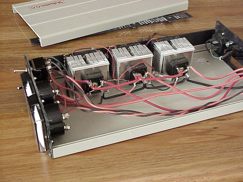
Just got a puff of breeze before and the fans run nicely, I guess in another couple of weeks I'll get a decent breeze to test it with! Oh, before you ask - the extra wiring is for the PV cells, seems sensible to put the PV ammeter in here, and a switch so I can dump PV to the main battery bank or top up the secondary bank to keep it in good condition. |
||||
