
|
|
Forum Index : Electronics : PWM - using picaxe 08M
| Author | Message | ||||
| GWatPE Senior Member Joined: 01/09/2006 Location: AustraliaPosts: 2127 |
I have had some good success with the testing of the battery regulator on my mill. I have confirmed that the load resistance has little bearing on the regulation. As long as the resistance is low enough and of sufficient power rating to dissipate the max output of the mill then the regulation works to within 100mV without a battery connected. Will be more precise with a battery. I tested with 1 ohm up to 8 ohms. Max output today was 6 amps only. Not a lot of wind. When I increased the dump load from 4 ohms to 8 ohms the cct no longer regulated at the maximum power level, as expected. Below this power, the mill output voltage was held at the set point 29.5V when the wind was strong enough. When the 1 ohm resistance was used, the voltage never rose above 29.6V. The higher peak currents do cause a higher dissipation in the MOSfet. I have a Version 2 now. This has auto detect system voltage of 12,24,36 or 48V. The cct detects battery voltage at power up. I was not able to incorporate cell failure detection though. If the cct voltage falls outside preset values for a system voltage, then an LED will flash, the fault output will enable and the cct will try and re-establish the number of cells again. I had to completely redo the code. If there is a problem with the battery system, then the cct will shut down and flash the LED. The additional output is enabled to keep a relay turned on that would be used to enable the mill brake mechanim. I will look into costing a 20A version without dump load if there is sufficient demand. The wind MPPT and a solar MPPT are looking promising as well. cheers, Gordon. become more energy aware |
||||
Highlander Senior Member Joined: 03/10/2006 Location: AustraliaPosts: 266 |
Sounds good, I can't speak for everyone but I would like to see an adjustable charge voltage. Sealed L/A require a lower charge voltage than flooded. How would that be set? Component or in the picaxe programming? Maybe a provision to add extra fets to increase amp capacity? Some of the guys are making double stator mills which may exceed 20A (depending on voltage) You said a 20A version without dump load. I assume you mean with the provision for dump, but without the actual dump load itself, is that right? Also big terminals would be nice Central Victorian highlands |
||||
Gill Senior Member Joined: 11/11/2006 Location: AustraliaPosts: 669 |
G'day Highlander, You make a good point regarding the ability to adjust the set point voltage. I feel that those buying a unit are those less likely to be able to make and/or programme their own so any adjustment would need to be accessible by them. As for the extra amp capability, I think 20 amps is fine. This is not the ultimate in regulators but it is different to what else is available and I feel better for my system. It is built for simplicity and price but still reliable at what it does. Great for your basic F&P. "mill brake mechanism"? That's gotta be just a frill to use up the spare output pin. I do things like that all the time too. Well that's my opinion of what it should be like. Gordon, I don't think you'll get many expressions of interest without some idea of price, and I understand you don't want to go to the trouble of haggling a bulk price from suppliers if then nobody wants one. Bit of a catch 22 really. Put it this way, would you expect it to be more or less than the current Oatley wind reg K241 @ $58 ? was working fine... til the smoke got out. Cheers Gill _Cairns, FNQ |
||||
| Gill Senior Member Joined: 11/11/2006 Location: AustraliaPosts: 669 |
G'day fellas, Sometimes I just can't help myself. I'd been planning to do this for a long time and now with Gordon's great little basic unit, I've wasted a weekend and modified Gizmo's Charger 1.2. I hope I've given it PWM(not been built yet). If you have an eye for this sort of sh*t please run your eye over it for errors. All constructive comments welcome. I've tried to stick as much as possible to the original but replaced the switching regulation with PWM regulation. Operation has three basic phases plus two manual modes. The three phases are BOOST Charging, TAPER Charging and FLOAT Charging. The two manual operations are Forced BOOST (Equalisation)and Forced (dump)LOAD. BOOST Charging: Full Amps sent to battery. TAPER Charging: Amps are progressively reduced in 10 increments Float: Amps are reduced to a voltage maintaining level. The Voltage set-points for BOOST and FLOAT are variable from the default by the user through the Menu. Still This is not the ultimate. My TAPER Charge tapers off in 10 steps and whilst I could select any number of steps, calculations are limited by integer variables(software limits for those who don't speak PICAXE). Also tapering is of the amps amplitude whereas it would be better to taper by clipping the higher amps. This would allow charge from less windy days to be not affected until nearer float end of taper. I have no idea of how to do these things(yet). OK so here's a link to the code and circuit: Click Here I think one could retro fit this to an existing unit. If you are dareing and do, let us know how it goes? was working fine... til the smoke got out. Cheers Gill _Cairns, FNQ |
||||
| GWatPE Senior Member Joined: 01/09/2006 Location: AustraliaPosts: 2127 |
Hi All, I think you will appreciate that this thread was intended for PWM using picaxe 08M. Gill wrote "mill brake mechanism"? That's gotta be just a frill to use up the spare output pin. I do things like that all the time too. There is a perfectly valid reason for the output control and the LED indicator output. Some indication is required for the operator to know of an error condition and if an error occurs then some backup system has to be enabled to deal with it. This is a logical requirement. The picaxe 08M code I have written is a KISS cct. This is a PWM mill dump load control. It will make a mill safe even if there is no battery connected. If a battery is connected, then a typical system voltage is checked and the appropriate maximum battery voltage is maintained with the dump load. This is not a battery charging controller, to maintain the battery. There are plenty of complicated ccts that have many more menus and settings that are available. I was under the impression that there was a requirement to have a simple automatic regulator that would do a better job than an oatley cct. Most will realize that the purpose of a dump load is to protect the mill from over-revving, and to limit the maximum applied voltage to the battery. This voltage is not particularly critical, and for a 24V flooded system a cuttoff of 29.5V would be OK. The cut off voltage on my 24V GEL-cell battery is 29.4V. It would be interesting for anyone willing to make Gill's cct to check the response time of the control. I have looked briefly at the code provided and there are many lines of code in the control loops. I found that using an 08M picaxe at 4MHz, I had to keep the instructions within the control loop to less than a maximum of 8 for effective control. Maybe someone who knows how to program a picaxe in assembler might get away with some more lines of code, but I don't. I would expect that PWM dump load controller would be somewhere $50-$100. Cct designers will appreciate that PWM of a MOSfet at 4kHz will incur increased power dissipation compared to just ON/OFF at a 1 second rate. A heqatsink may be required and current capacity will determine termination sizes. I have seen many complicated commercial designs that break when someone pushes the ok button at the wrong time, and system damage occurs, usually when no one is home to detect a problem. I think some clarity on readers requirements is needed. cheers for now, Gordon. become more energy aware |
||||
| GWatPE Senior Member Joined: 01/09/2006 Location: AustraliaPosts: 2127 |
Hi Gizmo and Gill, I have some questions. What is the purpose of the OFF position on your controller? Why would you want to turn OFF the mill protection? I cannot see from the picaxe code given where any battery regulation control is, when the switch is in the boost position. This is a manual control! The code seems to just disable the dump load and then display the measured current and amps, until the switch is manually rotated back to ON. I see that logging stops if the user is in a menu part of the program, and continues during manual boost or dump operation. I suppose this allows the operator to record the battery voltage at these times, even if nothing can be done automatically. How large a heatsink do you think should be used on the MOSfets when the cct uses PWM control? Have you used opto couplers and resistors successfully as MOSfet drivers in PWM control? There is a problem in changing some software and thinking the same hardware will perform a better task. There is a lot of code mixed up in the control loop. I cannot offer a solution, except to keep the display program separate to the control program. cheers, Gordon. become more energy aware |
||||
| Gill Senior Member Joined: 11/11/2006 Location: AustraliaPosts: 669 |
G'day Gordon, My apologies. My intention was not to hijack the thread but promote discussion of PWM regulation in general. But you are correct, the topic is well defined and excludes my post. I will therefor divert to a new one. Sorry once again. As I have already said, I believe the basic 08M PWM regulator to be the one most suited to the needs of most users. That some users will want fewer or more features can be expected. Why not pause a bit and see if any further requests are made? was working fine... til the smoke got out. Cheers Gill _Cairns, FNQ |
||||
| GWatPE Senior Member Joined: 01/09/2006 Location: AustraliaPosts: 2127 |
No worries Gill, PWM requires much better control of the MOSfet switches. I have my own preferences in this areaa. I will continue to monitor these posts to see the number of interested persons in the KISS approach. I am going to look at a boost-buck cct that can be used for any MPPT application next. This will require external logic as the micro has only a single PWM output. The biological computer says it can be done. cheers, Gordon. become more energy aware |
||||
| Gizmo Admin Group Joined: 05/06/2004 Location: AustraliaPosts: 5017 |
I just had an email from a reader Cliff Wylie, who said he tried the PicAxe MPPT code I posted in the original MPPT forum thread. Cliff said the code does work once the systax is fixed, but noted I used the sleep command to add delays in the loops. As Cliff pointed out, Sleep ( and Nap ) will actually stop the PWM output! Not what I intended. The Pause comand is the correct way to add delays when using PWMOUT. Answering some of Gordons questions about the PicAxe Charger Controller. This is the charger controller I use for my windmill and solar panels, the Off switch is handy if I just want to open circuit the whole system for measuring true battery drain or when I'm making wiring changes, the forced charge I use to give a bit of a battery top up if I know I'll be using the shed lights till late, forced load when I want to slow the windmill down. I'm a bit like Gill, like lots of buttons and options. Glenn The best time to plant a tree was twenty years ago, the second best time is right now. JAQ |
||||
| GWatPE Senior Member Joined: 01/09/2006 Location: AustraliaPosts: 2127 |
Hi all, I have updated the MPPT thread with my latest PWM buck boost General purpose MPPT control description. I test and record performance all of my designs. The bells and whistles are great if you have the time to keep on top of all the data. I have standardized my logging to a 6 second data recording interval. I record battery volts, free power generated amps, mains battery recharging amps and battery amps fed back to the grid. I currently use Excel to manage the data and give some graphical representation. I record once daily the cumulative kWhr produced by my renewables and the kWhr consumed from and exported to the grid. A spreadsheet keeps a running total of my profit/loss tally. For the last 18 months I have piad the utility < $100. Power is costing me less than if I had the connection and did not consume any power at all. We used to have $1200-$1500pa power bills. capital payback in about 8years. Can't wait for the buyback rate to be 45c/unit. I intend to use a picaxe 08M as the building block for a multi channel logger. Now that I have found a way to digitally transfer analogue data between micro's. No code timing problems and electrical isolation problems is solved. I have maintained the 10bit resolution as well. If the big brother AXE 28X2 becomes available, with 12 analoge inputs, the data logging will be a snap. here is a pinout of the chip. 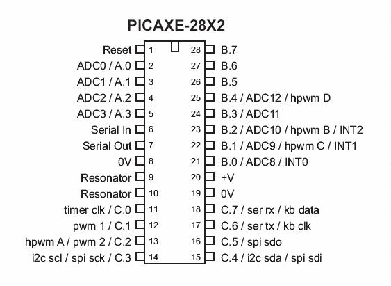
The chip above is not available yet, so I will look at a retrofit system. A multplexer added to a Jaycar available, Velleman USB experimenters kit. I was having trouble with ground loops and related offset errors, but now My original VB6, 16 channel logger can be used. The reason I suggest an alternative to Gizmos logger is the many more channels that are able to be recorded. My version of VB6 is the enterprise type and I have not been able to read a COM port, but USB is not a problem with the functions velleman provide. The velleman USB drivers support > 100 readings per second. here is a demo of the VB6 front end I have started for a logger. 2007-11-28_104445_demo.zip This is a fully operational program. If an experimenter board is connected you will see the parameter boxes changing. The program tests to see if a USB is connected and allows the file name to be specified. If no name given, then a log file with a time and date stamp is created. The cumulated totals are only for the current logging period. The data is updated and stored to the disk file. The data is not lost if the computer locks up, but logging stops at that point. My current off the shelf Velleman 4 channel logger loses all the current log file data if the computer locks up. Not happy Jane. I think all the various display windows are self explanatory. The logging interval can be adjusted from 1 to 10 seconds. The efficiency of the MPPT for the wind generator and solar pannel is also displayed. I will be able to make the analogue to digital to analogue optically isolated converter available. This would be a v-small PCB. The PIC would be preprogrammed to match the specification of the std PIC, but with optical isolation. Will keep readers updated with photo of finished prototype. cheers, Gordon. become more energy aware |
||||
