
|
|
Forum Index : Electronics : PWM Regulation _ Ideas?
| Author | Message | ||||
Gill Senior Member Joined: 11/11/2006 Location: AustraliaPosts: 669 |
G'day All, Hopefully we can bring out different views on any aspect of Pulse Width Mode Regulation. Unfortunately I started on this topic on Gordon's thread Here with a post on a PWM modification to Gizmo's Charger 1.2. Circuit and Code. I invited criticism (constructive of course) of what I had done. Gordon has suggested the response time will be slow due to many lines of code. Also that the more buttons and features, the more prone to failure. I now respond by saying I agree with both observations. Firstly on the response; In the old CB Radio days we considered a battery charger and battery to be as good as a regulated power supply. The battery acts as a regulator. So what we are doing here is regulating the voltage of the regulator. We all know that battery voltage increase is as slow as an old age pensioner walking to the shops. Most days I feel my pensioner has a walking frame, it is that slow. A battery takes hours to charge as the voltage rise is slow. With PWM from the PICAXE the PWM is ticking over continuously in the background(4,000 corrections per seconds), and it is only those slow increases that the duty cycle has to adjust to. If it were the amps output from the mill on a gusty day..... whole different story, but for slow old battery voltage, even the slower response of reading a few more lines of code will not have my pensioner wandering wrong streets unescorted. Secondly; I like knobs and buttons and displays and controls and adjustments. Undoubtedly the highest degree of reliability is the price we pay for this. Some will want to set and forget, others will want to fiddle. What more can I say? I am updating the code and circuit as I become aware of errors/improvements. I'll start on making the circuit soon. Any ideas?? was working fine... til the smoke got out. Cheers Gill _Cairns, FNQ |
||||
| GWatPE Senior Member Joined: 01/09/2006 Location: AustraliaPosts: 2127 |
Hi Gill, I will try and explain a little. With PWM from the PICAXE the PWM is ticking over continuously in the background(4,000 corrections per seconds), and it is only those slow increases that the duty cycle has to adjust to. This statement is untrue. Basically, The PWM output from the picaxe is a pulse train of constant pulsewidths of the set duty cycle for the duration until the next time the PWM command is executed with a different duty cycle. There are not 4000 correction per second. [This is what usually happens with an analogue type PWM controller, but not a digital one] I can probably post an actual recorded acount of how much [how far] the duty cycle of the modulator changes as the energy from a gust of wind is dissipated into a dump load to maintain a constant voltage. I will need to check with Gizmo about posting a short video clip showing CRO trace of a digital modulator in action. I can assure you that when a battery is fully charged the efffective charging impedance of the battery is high. At the point we wish to regulate, the battery impedance increases to be similar to the dump load. As the voltage increases further, the battery charging impedance becomes infinite and the dump load is the only impedance the mill sees. The energy is not absorbed by the battery and the voltage will rise rapidly with the energy from the mill using control with a slowly responding PWM. In the picaxe code you submitted. nap 10 - ??? nap has values between 0-7 I think this will default to nap 2. you may have to test youself. also the nap command stops all timers and PWM output. [according to the manual] [NOT what we want] Gizmo can probably confirm this. [this was not an issue with his design] within the control loop following the main label. To get to the float test, more than 120 instructions are executed and within float an additional 67 instructions. Remember I had to cut the instructions within the control loop to < 10, for effective modulator control. I hope you can make some sense of my explanation and I think you will find that separating out the control from the display functions will help [2 separate micros] You will need to transfer data between them though. cheers, Gordon. become more energy aware |
||||
herbnz Senior Member Joined: 18/02/2007 Location: New ZealandPosts: 258 |
hi First I must say I have gone of PWM in the sense being discussed on this forum I have presented briefy my aguments on other threads with no resulting interest to warrant expansion. I assume we are building a dump load controller for batteries being feed from a wind mill. In the world of alternative energy it is rare for a mill to be the sole supply to the batteries so any usuful controller will be a battery requlator speed response is not important as the battery will absorb rapid changes. I have in the course of my work seen Trace & Tristar controllers fail. Two main reasons One the dump load is not large enough to absorb all the generating capacity I would always recommend twice size of all combined loads. Secondly a failure of a battery or connection allowing a rapid rise in voltage due to open cct volts of all hydro milss and solar rise dramaticly of load. I nowdays use a requlator in the supply to the electronis of the controller along with a SCR That shorts out the supply and blows the fuse if volts go to 36 volts on a 24 volt system.(crowbar system) Also thought should be to supply a output to control a 230 volt water heater Can still Use PWM if a solid state relay is fitted in the house board. 24 volt elements never work in practice unless the water heater is right beside the batteries. This however does lead on to a backup dump in case of inverter failure etc. In a recent instalation I have designed I merely provided a contactor that shorted out the ac side of the Smart drive if the controller sensed 33 Volts .I notice that installers are nowdays putting two controllers in as backup. I like the idea of using a picaxe and would see great potential to come up with a good controller for a hybrid system at present all the commercial units are adapted from solar units all use PWM that does not suit me however tristar has now incorporated a on /off feature. Some form of triming is necessary for the consumer that can not program via a computer, for reliablity this needs at least two buttons to be pushed that step up a set point in memory Keep up good work Gill Gaining a understanding og pic programs is the main thing us lazy individuals can then learn from your generosity in publising your code and put our own crazy ideas in and try them out and hopefully pass on ideas failures just as immportant as succsess. Herb |
||||
| herbnz Senior Member Joined: 18/02/2007 Location: New ZealandPosts: 258 |
Hi Gordon this statement I can not agree with "At the point we wish to regulate, the battery impedance increases to be similar to the dump load. As the voltage increases further, the battery charging impedance becomes infinite and the dump load is the only impedance the mill sees. The energy is not absorbed by the battery and the voltage will rise rapidly with the energy from the mill using control with a slowly responding PWM" The back emf of the battery will only allow current to flow in battery if supply is higher and if your dump is on it should insure that this voltage is lower no current flow into the battery in fact usually flows out, the case however when dump is in a off cycle battery can draw current impedance does not change.. impedance change is minor and very gradual hence reason discharge tests can be performed on batteries withless than full charge. In my teaching days it was a routine lab assignment to determine battery impedance of different batteries at different charge levels. |
||||
| Gill Senior Member Joined: 11/11/2006 Location: AustraliaPosts: 669 |
Thank you all for your input on my project. I truly appreciate the feedback as there is a lot I am learning even when refuting an assertion I disagree with. It makes me think. Several quires and points have been raised so I will try to cover then. The OFF Switch, very handy for petrol generator's equalising charge. Full operator manual monitoring and recording of volts, amps and batt temp during this task. Forced Boost turns regulation off, Yes for equalising charge as above. Though not always enough energy from RE sources for this one. No logging during Menu adjustment. OK, but I don't feel that is a big issue. The need for adjustment would be rare. Heat sinks, Good query. I don't know. From your earlier comments we will need more. I guess that will be a "suck it and see" so will make accordingly yet allow for changes if HOT. Opto's driving MOSfets in PWM experience. No I've had none. Exciting experiment. Hay. If it's not satisfactory I plan to bypass it and go direct. Too much code? I don't see it that way as I don't see sudden battery voltage changes you imply. And from this thread: The 4,000 corrections per second I refer to is the Period and the corrections to to battery input is the Duty cycle. I do not mean an adjusting correction of the duty cycle. I do accept I chose a bad turn of phrase to express this. Thanks for the 'heads up' on the nap command. That one slipped by me as have not used it before. Disaster averted. And back to the response time thing again, I think I owe you one "I told you so" if, and I mean IF, it doesn't work for this reason. Now to Herb, So many little bits and pieces in there is greatly appreciated. Your setup is unsuitable for me as the only time 240 is on is when I'm home and using it. Why do Poms and Kiwis always want to heat water? It's got me beat. You should live somewhere where there is sunshine and it's warm. ha ha. Over do the dump load rather than have to little, is noted. Ta. Well that's it for tonight. Cheers. was working fine... til the smoke got out. Cheers Gill _Cairns, FNQ |
||||
| GWatPE Senior Member Joined: 01/09/2006 Location: AustraliaPosts: 2127 |
No worries Gill, I guess none of us are experts. We are all still learning from others. I think that PWM can work well. I think multiple specialist components are needed. If the cct is placed correctly then no switches have to be used and the system is set and forget. A dump load controller is not a battery regulator. The PWM behaves like it, but we are really wanting a cct to protect the mill and battery. We do get distracted at inoportune times and this is when things can go wrong. Good luck with your testing. cheers, Gordon. become more energy aware |
||||
| Gill Senior Member Joined: 11/11/2006 Location: AustraliaPosts: 669 |
For those trying to follow this thread on PWM regulation, here's a few little graphs for those(like me) who need a little visual input too. WIND GENERATOR REGULATORS 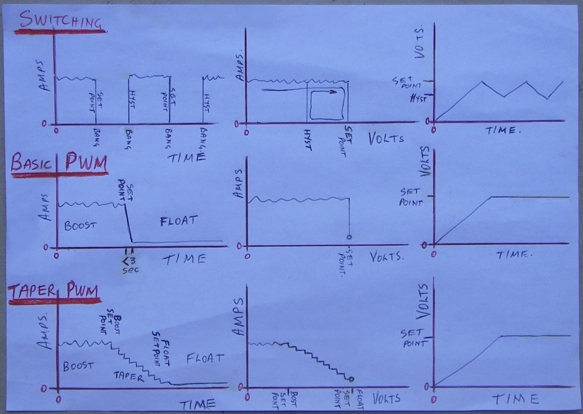
correction: the two little circles should sit on the 0 line What we all use(to my knowledge) is the top one. Gordon's project is the middle one. You Beauty! And I am about to attempt the lower one. The area of most concern with my proposal would be displayed by a large circle in the middle graph also shown as a ripple in the Float lines of the two outer graphs. I hold the optimistic view that it will be well within acceptable levels, so I have to make it and see. I am a plodder at making things, but it will happen soon. was working fine... til the smoke got out. Cheers Gill _Cairns, FNQ |
||||
| Gill Senior Member Joined: 11/11/2006 Location: AustraliaPosts: 669 |
An update for those interested. I have improved and updated the Float code. Here is an excerpt showing the area in question. Float: byt = 192 ' move to 2nd line on screen GOSUB SendCmdByte FOR get = 38 TO 48 READ get,byt GOSUB SendDataByte ' Display "FLOAT Chrg" NEXT low 1 low portc 5 high 0 ; Float Chge LED ON FOR taper = 1 to 100 ;temp use of 'taper' to count with as b0 & b1 (as w0) in use if volt > floatV then if duty < 1000 then inc duty: endif 'test for overflow and increment duty else if duty > 0 then dec duty: endif 'test for underflow and decrement duty endif pwmout 1, 249, duty 'Update duty cycle. 249 = 4kHz @ 4MHz readadc10 0,w0 ' read in volts let w0=w0 min 100 let w0=w0 max 355 Volt = w0 - 100 NEXT taper goto Main That's now just 11 lines of code that loops 100 times. In each loop it reads Volts, selects changes to duty cycle, then updates the duty cycle. After 100 loops it's off to update the display and log then back again for another 100 loops. That should be better.  was working fine... til the smoke got out. Cheers Gill _Cairns, FNQ |
||||
| Gill Senior Member Joined: 11/11/2006 Location: AustraliaPosts: 669 |
Here's a piece of code I wrote for the Gizmo PicLog though it would now have to be Ver1-3, because the relay version has to be replaced by MOSFET switching for PWM regulation. The breakthrough for me is that this is not Taper PWM by stepping (10 steps in my modified Gizmo's Charger code), but fully adjusting Taper PWM regulation as a product of volts and amps. This is the solution to the amp clipping method I stated in a earlier post as a better way to go. One downside to this method is that with the PICAXE 08M, only one amp reading can be taken and that has to be generator output and not battery input(or both) as most(I) would like. I have no time to show a circuit for this one yet as am busy making the Gizmo Charger Mod. Unfortunately this new code will not slip easily into Gizmo's Charger's PICAXE28X code package and full display of volts and both amperages will be difficult. This LINK contains: Code Algorithm for taper PWM duty cycle explained Circuit (layout hint only - not for construction) Comparison of PWM methods; The basic method has a full boost charge until a 'voltage set point' where it then maintains this voltage with a dribble charge as required. The Taper PWM by stepping method allows full boost current to a 'boost voltage set point', then reduces the charge in 10 voltage steps to a 'float voltage set point', where it then maintains this voltage with a dribble charge as required. And now, Smart Taper PWM allows full boost current to a 'boost voltage set point', then reduces the charge by an amount calculated from input watts to a 'float voltage set point', where it then maintains this voltage with a dribble charge as required. The purpose of tapering off the charge at the end of the charge cycle is to reduce gassing and heating of the batteries which occurs at the end of the charge cycle and is more of a problem with high amp inputs. I have such a problem with my F&P micro hydro when in use and requires constant topping up of the batteries. Wind and solar that have high amp inputs are no different. Tapering has been a feature of solar PWM for well over 10 years but we will soon do it with DIY PWM shunt regulation too. The benefits of this latest method is that it allows far less tapering off of the low amps charge of breezy days, but on windy days when the amps are really pumping, it reins them in progressively til float voltage is achieved. More gooderer.
And for that other feature of commercial solar regulators? It is my opinion that the equalising charge feature on solar regulators is not desirable for wind regulators at this time. But others may think diferently. Ask me again in a few years.... was working fine... til the smoke got out. Cheers Gill _Cairns, FNQ |
||||
| GWatPE Senior Member Joined: 01/09/2006 Location: AustraliaPosts: 2127 |
Hi Gill, With reference to the code contained in the above link. What is Max amps referring to. I assume it is mill output amps? I have looked at the code and I can see that below Volts = 350 then all power goes to battery, no dump load ON, then between Volts = 350 and 395 the code throttles power to the dump load proportional to the power from the mill. Above Volts = 400 the code controls the PWM to maintain Volts at 400 by throttling the dump load. can you give approximate battery voltages that you would expect the 350 and 400 settings to be? Would the float section of the code relate to say a float voltage on a 24V system of 27.6V? cheers, Gordon. become more energy aware |
||||
| Gill Senior Member Joined: 11/11/2006 Location: AustraliaPosts: 669 |
G'day Gordon, Yes mate you've got it sussed. I had updated the download .zip file but you must have beat me to it. Max Amps is Max gen output possible as PWM needs to cope with all possible power and without programme calculation overflows when in use. The figures used for explanation are exemplary ones only. In reality one would need to apply the desired voltage and read the ADC input for the exact figure to use, alternatively, select a figure and and calibrate by adjusting the voltage divider to achieve the voltage/ADC figure wanted. This is why I've given the full breakdown of the calculation, so that whatever figure applicable to the individual circuit can be substituted if new set points are wanted. The PICAXE with this code can be applied to any voltage system but calibration and/or programme tweaking of the set point figures will be needed on construction. was working fine... til the smoke got out. Cheers Gill _Cairns, FNQ |
||||
| GWatPE Senior Member Joined: 01/09/2006 Location: AustraliaPosts: 2127 |
Hi Gill, This is what I was hoping you would answer. cheers, Gordon become more energy aware |
||||
| GWatPE Senior Member Joined: 01/09/2006 Location: AustraliaPosts: 2127 |
Hi Gill, I have tested your code on my picaxe prototyping board. The PWM pin2 output, I routed to my mosfet drive cct that connected a dump resistor accross the supply. I noticed that with your code,the output PWM signal jumps one way and then eases back. This happens due to the way your code is written and the response time of the modulator to change. During the taper mode, the pulse width is recalculated from the voltage reading but the amps are not measured again. This overestimates the required pulsewidth and makes the pulsewidth wider than it needes to be. This wider PWM signal on the dump load drags the voltage down. The code within the for/next loop reduces the pulsewidth only with relation to the battery voltage. The amps value is the value originally read in the main code loop. The code introduces a cyclic behavior to the battery voltage. The float part of the code has some strange behavior as well. This may be attributed to an undefined value of duty upon entering the float code. duty is only calculated in the taper code. the float only increments or decrements duty depending on whether the voltage is greater than 400 or lessthan=400. The value of duty can only be adjusted by 100 during the for/next loop before the control goes back to the main loop with the logging code. The data logging introduces a huge bottleneck in the program execution speed. The code responds much faster without the sertxd code. The code I have written locks the modulator pulse width onto the power level required to maintain the set voltage. As soon as the voltage rises to the set point the modulator responds and follows the required power level, up or down. There is no jumping of the PWM signal. The cct I have made is not intended to charge batteries, but to protect the battery and mill by controlling a dump load at a defined voltage without introducing a discharge charge ripple current on the battery. I wish there was some way to post video of CRO output to show other readers what happens with the different code and the same electrical config. I tried to add some recording output to my code as well, but I have decided that it degrades the operation of the cct too much. It is better to use a separate micro if you want to log data. If you have 1 second delays somewhere in a control loop then this may give a logging time window. My conclusion is that taper regulation should not produce a PWM output that your code appears to produce. The code would probably work using a battery charger. A mill produces rapidly changing power output and it is important for a regulation type cct to be able to rapidly respond to these requirements. The only fixes I can give is to read both amps and volts each time and remove logging function from the control loop. cheers, Gordon. become more energy aware |
||||
| Gill Senior Member Joined: 11/11/2006 Location: AustraliaPosts: 669 |
G'day Gordon, Your test worries me in that the description of your test setup does not indicate a battery is connected. Surely any objective test must test for the purpose for which the device is designed and intended? Also your comment on taper mode not reading amps on every update of duty cycle is incorrect. That is the the whole guts of this mode. Please recheck your code as I have rechecked the download code and it is there. Next, you say the code does not progress into Float without a defined duty cycle. Entry to Float is from Taper, and the last Duty cycle there still applies on entry to Float. This ensures the continuity of duty cycle that you have missed. Yes logging will slow down PWM updating briefly (for 1 pass in 100) but so what, that is updating only, remember the execution of PWM always continues in the background for this brief time. What battery voltage runaway did you record as a result? This is after all a PicLog. For those inclined toward less logging updates, the loop of 100 counts could be increased to a much larger figure, though deleting logging altogether with it's few lines of code would mean having to come up with a new name. Fortunately, at no time does your test results report a failure of the device to satisfactorily achieve it's intended purpose. Unfortunately, I don't think it was tested for it's intended purpose. was working fine... til the smoke got out. Cheers Gill _Cairns, FNQ |
||||
| GWatPE Senior Member Joined: 01/09/2006 Location: AustraliaPosts: 2127 |
Hi Gill, Yes, somehow a line of code re measuring the amps fell off the upload file. There was enough wind today for testing. The code does regulate. I still noticed some hunting though in the float operation. It may be due to the time constant on the battery voltage sensing input. I will not persue it though. Good work Gill. I design my ccts for worse case. This includes one where a battery lead comes off, or corrosion restricts current flow, etc. My ccts have to do their job, even if this happens. This is what I expect from automatic control. I have some form of foldback protection ahead of every vulnerable component including rectifier, slip rings and MPPT. My setup will work without a battery connected, even though I do have a battery in the system at the moment. I regulate the voltage by feeding back to the grid. If the grid fails, then my system self protects by regulating all the power inputs to the battery. All happens automatically. My battery spends most of its time during the day at 27.7V, and my 24VDC to 240VAC inverter is bypassed. Today the power went off for a few minutes. The main solar array shut down with the grid connect inverter. The 24VDC inverter was reconnected. The smaller array MPPT then boosted the battery to 29.5V. This triggered the mill shutdown. The solar MPPT regulated the battery back to 27.9V. The mill then cycled on and off in a casual manner. [The mill MPPT starts producing output at a generator voltage of 10V, around 5W output.] The system restored to normal operation when the power came back on. I do not use a dump load, as I can just electronically short my mill output with the MPPT cct, in any conditions. I have to get back to the AXE-08M MPPT project now. cheers, Gordon. become more energy aware |
||||
