
|
|
Forum Index : Electronics : Flat Stator Windings?
| Author | Message | ||||
Domino Newbie Joined: 22/01/2008 Location: United StatesPosts: 7 |
Greetings to everyone. I hope this isn't a dumb question but I have been searching for an answer to this for quite a while with no success. As far as stator windings are concerned, which is more important to power generation the amount (weight/thickness) of copper used or the number of winds? For instance, if I had the ability to replace the wire windings on the Smart Drive with flat copper sheet or foil, with the exact same amount of copper as the wire windings, would the solid piece of copper conduct the same amount of power as the windings? I have seen some new innovations in stators and some of them "appear" to be using flat copper windings. I have a photo of one if I can figure out how to post it. Cheers, Jeff |
||||
| Gizmo Admin Group Joined: 05/06/2004 Location: AustraliaPosts: 5015 |
Hi Jeff Flat wire windings do give a better copper densty, with less dead space in the magnet field. You will see this sort of wire in some heavy duty transformers. So while flat wire would give a higher output, there are a couple of problems. Its hard to wind in tight places without kinking, and the start lead needs to be folded over so it can exit the coil, creating a lump, and loosing some of the copper density we gain by using flat wire. Round copper wire is just a lot easier to use in the manufacturing process. Glenn The best time to plant a tree was twenty years ago, the second best time is right now. JAQ |
||||
| davef Guru Joined: 14/05/2006 Location: New ZealandPosts: 499 |
Based on my RF knowledge . . . flattening the wire gives more surface area than a round wire. At frequencies where the "skin effect" because significant you are able to decrease the loss in coils, ie windings. Determine the maximum frequency the SmartDrive unit is spinning at its maximum rated RPM. Then dig out the formulae for skin depth or look here In copper, the skin depth at various frequencies is shown below. frequency d 60 Hz 8.57 mm 10 kHz 0.66 mm 100 kHz 0.21 mm 1 MHz 66 �m 10 MHz 21 �m From this table skin depth is about 7mm at 1kHz. I would guess you would need to be up around 10kHz before there was much improvement over using the wires sizes found on standard SmartDrives. Another option is to buy Litz wire or make your own by winding many smaller wires in a bundle. |
||||
| Domino Newbie Joined: 22/01/2008 Location: United StatesPosts: 7 |
Thanks for the replys! This is actually for a home built design based on a larger scale of the model in the photo. I am considering the flat copper coils wrapped wround the arm where this guy used wire windings. 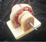
If I were to try this experiment, do you think the use of a heavy copper foil tape with non-conductive adhesive,(as an insulator) carried by most craft shops, would do the job? You can get a couple hundred winds per with this stuff and have almost no air gaps. Would the increased density even be worth the conductive gain and coil loss or would the tape possibly even fail at higher levels because it is too thin? (copper foil locally is usually between 0.05mm-0.075mm. In comparison aluminum foil is roughly 0.016mm-0.024mm) Cheers, Jeff |
||||
Gill Senior Member Joined: 11/11/2006 Location: AustraliaPosts: 669 |
G'day Domino, It appears to me that your proposed use of copper tape is more inspired by novelty, convenience and availability than a dedicated experiment in improving generator efficiency. If so my comments may be worth assessing. As I see it, the number of turns in a coil (all else being equal) is what gives you Voltage. More turns = more volts. The cross sectional area of the wire used relates to it's current carrying capacity. To small and the wire becomes a resistor causing generated power to be lost as heat, and too large causes a physical size problem and an increased cost. Find the exact tape thickness by say using a solvent to remove the adhesive then measure with a micrometer. Multiply by the width to give the area. This can then be equated to a round wire of same cross sectional area. To match the wire size stipulated (so it handles the current and won't burn out), it may be necessary to double or triple the tape per turn. A little more cross sectional area is better than less. Does this answer your query? was working fine... til the smoke got out. Cheers Gill _Cairns, FNQ |
||||
| Domino Newbie Joined: 22/01/2008 Location: United StatesPosts: 7 |
G'day Gill, You are right on with the use of the tape. I have checked everywhere locally and none carries an enameled flat wire, but some have heard of it ;) The copper tape was the best I could find with a coating. From the great advice you, davef, and Gizmo have offered I have some good info to go on. I will try this experiment and post results when I have them. Thx m8s! |
||||
