
|
|
Forum Index : Electronics : Warpspeed’s MOSFET mounting method
| Author | Message | ||||
| kanchana Regular Member Joined: 08/05/2018 Location: Sri LankaPosts: 56 |
Accidently my controller board touch the heatsink which is connected to power positive , controller board fried , some how i replaced all the ICs and got it working again. For the EPROM I used a one I had which is 29co2oc , I had a backuped the original epromcode before. Now i adjasted resisters and trim so that output is 220v at PSU voltage is 56V When I increased the voltage to 62V output jumped to 245V . Is this the correct response expected ? Or somehow I messed up the voltage regulation during repair ? Regards kanchana |
||||
| kanchana Regular Member Joined: 08/05/2018 Location: Sri LankaPosts: 56 |
Voltage sensing resiter was not correcly conected ,It is working nicely now Used boost converter which had to step up the battery voltage to 60V Connected smaller isolated PSUs to 60v Power for the mosfets connected direcly to the battery Soft start sequence as you sugested Succesfully tested with large battery bank up to 400W . Output voltage drops from 230V to 216 volts with 400w of load ?. Battery voltage steady at 55.75 volts Regards kanchana |
||||
| Warpspeed Guru Joined: 09/08/2007 Location: AustraliaPosts: 4406 |
It sounds like the voltage regulation part of the control board is not working. You should be able to adjust the inverter ac output voltage up and down very smoothly with the potentiometer on the control board. If that is not working maybe have a look at the analog to digital converter chip. Cheers, ĀTony. |
||||
| kanchana Regular Member Joined: 08/05/2018 Location: Sri LankaPosts: 56 |
But Now output votage stay the same with varying input voltage but it varies with the load , higher the load lower the AC output voltage? Regards kanchana |
||||
| Warpspeed Guru Joined: 09/08/2007 Location: AustraliaPosts: 4406 |
O/k so the dc input voltage can change and the ac output output stays constant, that is Āhow it is supposed to work. As you load it up, the output voltage will fall, but only slightly. In my own inverter its about two volts drop per kilowatt of load. The grid here goes up and down by about ten volts anyway, so I have not worried about it. Now if that is a concern, there is a way to fix it that Klaus has tested and is now using, Andrew has had success with this as well, and has incorporated it into his latest Nano software. The basic idea is to use dc input current measurement to compensate for increasing load, in the same way that changes in dc input voltage are corrected. As the load increases, the dc input current to the inverter also increases. We use that current increase to step down to an appropriate lower lookup table. Its like fooling the inverter that the dc input voltage is lower than it really is, and arranging it so the output does not sag under load. To do that, you need a Hall current sensor on the incoming dc, the type of Hall sensor that runs off +5v dc and provides nominally a +2.5v output at zero current, and something like up to +4v maximum output at maximum measured dc current. Now as you know, the voltage reference for the A/D converter on the control board comes from a TL431 +2.5v shunt regulator. That provides a constant fixed voltage source. The output from the Hall sensor can be considered a +2.5v "current compensated" voltage source, because it increases as dc input current increases by rather a large amount ! You certainly will not need anything like the full amount of compesation that is available, but only just enough (millivolts of correction) to offset voltage drop off under load. Amazingly, this also works wonderfully well when feeding reverse power back into the battery from a grid tie inverter. It prevents the ac voltage from rising. If you connect a potentiometer between the fixed +2.5v, and the "compensated" +2.5v from the Hall sensor, and use the output from the pot as the voltage reference for the A/D converter, you can tweak the pot to get any degree of current compensation you want, from none to a huge amount. Its then a case of firing up the inverter and adjusting the original potentiometer for the required ac output voltage under no load with compensation set to zero. Then connecting up a big load, and adjusting the current compensation potentiometer so there is little or no change in inverter output voltage. ĀI have not bothered to do this myself (yet) but if my inverter ever fails and I have to work on it, that modification will be included. ĀIts pretty easy to do. The hall sensor Klaus uses, and that I have here are both HSTS21 type. ĀThis is rather nice, it uses a split core so you can open it up and place it around a cable without having to thread the cable through a hole. It also has trim potentiometers on the sensor itself for zero and span. The particular one I have is rated for 100 amps dc, Klaus uses the 200 amp version. You can go pretty big, because only a small fraction of the output amplitude is usable for this. https://www.poweruc.pl/products/hall-split-core-current-sensor-hsts21-rated-input-50-100-200-300-400-500-600a-rated-output-42-5-0-625v?_pos=1&_sid=e58b6bdb7&_ss=r I bought mine from e-bay. Edited 2020-04-20 12:17 by Warpspeed Cheers, ĀTony. |
||||
| kanchana Regular Member Joined: 08/05/2018 Location: Sri LankaPosts: 56 |
Thanks, tony for excellent explanation and the cleverly done. What is the recommended method to filter the AC output? for the testing i used a 2uf cap and with the increasing load I notices the notch of the sine wave is becomes asymmetrical slightly Regards kanchana |
||||
| Warpspeed Guru Joined: 09/08/2007 Location: AustraliaPosts: 4406 |
I just used one of those commercial EMC filters type CW4L2-20A-S. These are the lowest frequency cutoff type I could find, the one above is rated 20 amps, but they are available both larger and smaller than that. https://reelen.en.made-in-china.com/product/eKwnRoQHaIYT/China-20A-Single-Phase-Double-Pole-Terminal-Type-EMI-Filter-with-Ce-Certificate-CW4L2-20A-S-.html https://www.ebay.com.au/sch/i.html?_from=R40&_trksid=m570.l1313&_nkw=CW4L2-20A-S&_sacat=0 I bought mine from e-bay. No real need for anything else, the waveform is very clean as it is. No high amplitude high frequency pwm to filter out! Have never had any EMC issues with the inverter over the last couple of years. Cheers, ĀTony. |
||||
| kanchana Regular Member Joined: 08/05/2018 Location: Sri LankaPosts: 56 |
Thanks tony for everything Regards kanchana |
||||
| Warpspeed Guru Joined: 09/08/2007 Location: AustraliaPosts: 4406 |
Its all been very enjoyable for me as well. There are now five different Warpinverters running built by five different people. Cheers, ĀTony. |
||||
renewableMark Guru Joined: 09/12/2017 Location: AustraliaPosts: 1678 |
Kanchana, good work mate! Great to see the effort made considering it was always going to be a small output machine in your case due to the small torroids you had on hand. Cheers Caveman Mark Off grid eastern Melb |
||||
| kanchana Regular Member Joined: 08/05/2018 Location: Sri LankaPosts: 56 |
Yes , Not tested up to full power , but this will be enough for regular loads Regards kanchana |
||||
| kanchana Regular Member Joined: 08/05/2018 Location: Sri LankaPosts: 56 |
While waiting for current sensor to arrive, it got me thinking I have some extra transformers with 230v primary, As I was initially prepared to do I can get from 230v Dc from mains/ Solar. In that case largest transformer is not needed. So, if i connect largest power-board output in series with other 3 transformer outputs will it work correctly? Will it cause problem during zero-volt step? Regards kanchana |
||||
| Warpspeed Guru Joined: 09/08/2007 Location: AustraliaPosts: 4406 |
I actually built something like that. In fact the picture on the first page of this thread was an early version Warpverter built without a large transformer. The second inverter used three identical 230v to 24v 300 Va transformers with the secondaries connected in series for 75v. Third inverter used another 230v to 24v 300Va transformer, and a fourth inverter a smaller 230v to 8v 100 Va transformer. Here is a picture of the same thing rebuilt into an old DOS computer case (minus the smallest toroid). 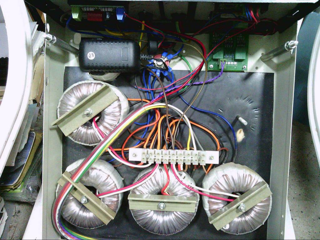 At one stage the largest inverter blew up, and fed 230v dc out to all my home appliances, and that did a LOT of damage  I would never attempt anything like that again, although it did seem like a good idea at the time  Cheers, ĀTony. |
||||
| kanchana Regular Member Joined: 08/05/2018 Location: Sri LankaPosts: 56 |
I will take your advice Tony , so what ever the input voltage , largest transformer is needed to isolate the output from the dc input Regards kanchana |
||||
| Warpspeed Guru Joined: 09/08/2007 Location: AustraliaPosts: 4406 |
Its definitely the safest way. Cheers, ĀTony. |
||||
