
|
|
Forum Index : Solar : Build a Mppt 3 Kw Charge Controller
| Author | Message | ||||
zaphod Regular Member Joined: 03/06/2018 Location: United KingdomPosts: 93 |
Hi Mike If you compromise slightly on the reselution/frequency A PIC24EPXXXMC20X will do up to 68Khz at 10 bit or double that at 9 bit. You get loads of pwm's, digital deadtme etc, ADC's and hardware multiply divide, 70Mips execution (when it feels like it) in a DIP or SMT package for a few $$$. I use it and like all MCU's has the usual crop of bugs to keep you busy  Cheers Roger 1Kwp DIY PV + Woodburner + Rainwater scavanger :) |
||||
| Solar Mike Guru Joined: 08/02/2015 Location: New ZealandPosts: 1125 |
Thanks for the suggestion zaphod, will investigate. Have made some changes to the power pwm module, when used in pwm only mode both mosfet switches must be used simultaneously, however when in mppt mode the upper PV switch (A) can be left on when active charging, only the lower switch (B) needs pwm applied to it. This makes it more efficient as only a single parallel set of mosfets are switching. So have re-arranged the schematic slightly, changing the mosfet orientations, noting that the lower switch (B) must have its body diode such that it will conduct if the synchronous rectification module manages to avoid my anti-spike protection and attempts to create high energy +ve spikes, the body diode will conduct and dump them into the main input capacitor. Finally did the calculations on the input cap, it must have 70 amp ripple rating and be min 4000uf, hate to think what that would cost, however by using 50 x 100uf 250 volt caps in parallel, will give the required spec. 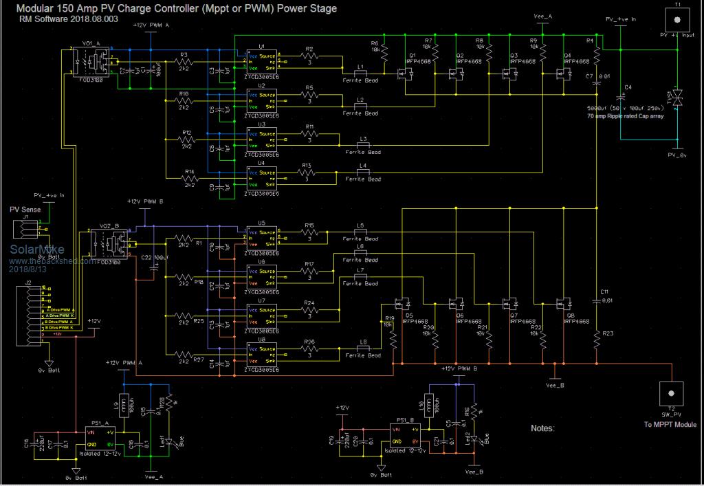 Cheers Mike |
||||
| Solar Mike Guru Joined: 08/02/2015 Location: New ZealandPosts: 1125 |
Right cracking on, completed prototype pcb for the above power module, only minor changes to the schematic, for heat sinking have decided to use alloy 30mm x 30mm x 6mm thick right angle for mounting the mosfets, it goes between the mosfets and the top pcb layer and acts as the common conductor for their drains, no insulators. The right angle bolts to the main case housing using nylon screws and a thin silpad insulator strip; at full power 8Kw output approx 60 watts of heat will be generated, so not much heat to get rid of. 45mm^2 copper bars bolt to the top copper areas for joining the mosfet source connections via a 4mm bolt and copper washer, mosfet pcb footprint pads not used except for the gate; bottom of pcb has a similar bar on underside as battery 0 volts common, 50 caps shown each with ceramic bypass (only used when mppt module connected, otherwise most are left out.) Bottom layout shows how the individual mosfet driver chips are connected, they require the large pad areas on the legs for heat sinking, should anyone want to use them in their own designs. 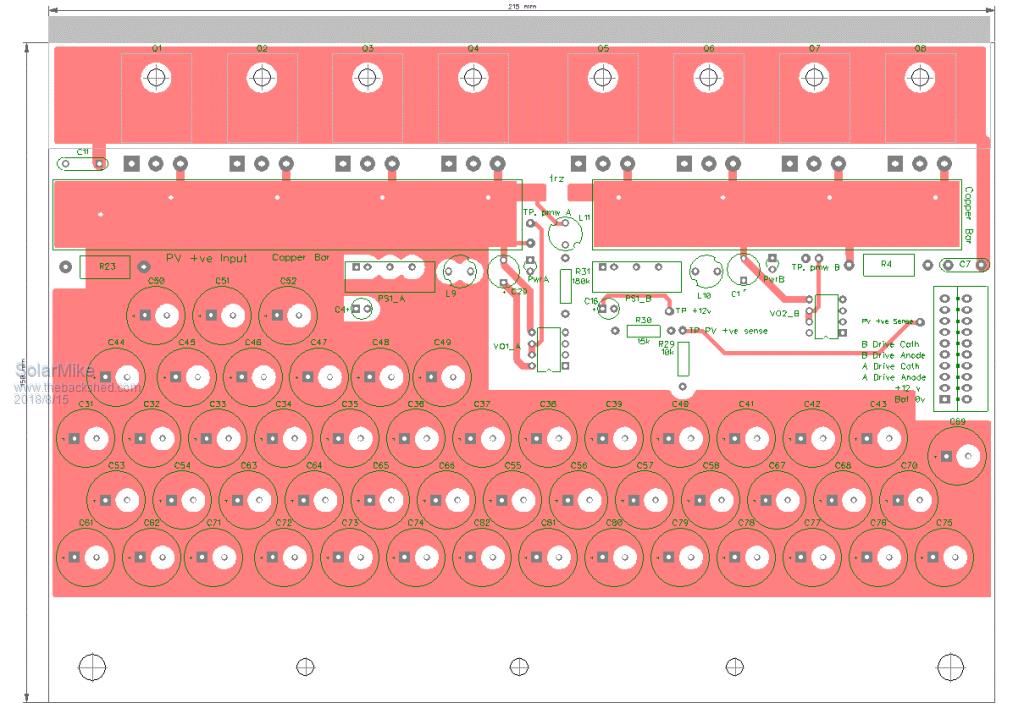 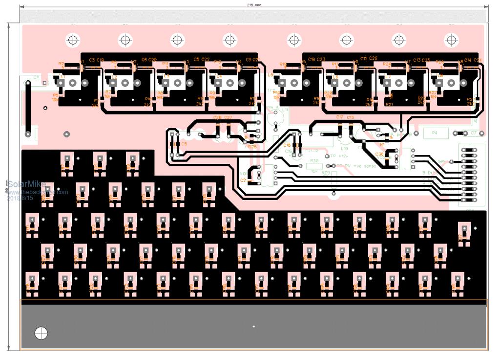 I think the mppt module will have a similar construction theme, haven't looked at it yet. Cheers Mike |
||||
| Solar Mike Guru Joined: 08/02/2015 Location: New ZealandPosts: 1125 |
Hmm some slight changes to the Mppt power schematic required: when laying out the pcb for the synchronous rectification module, I realized the 200V mosfets IRFP4668 have 4x the on resistance as the lower voltage types that would be used in PWM mode only. In Mppt mode the upper ones are not switching they are only on when actively charging, otherwise are turned off. The high voltage current at near 150-180 volts from the PV array will be approx 50 amps through these mosfets, so have reduced their number to 3 in parallel. the ones that discharge the main cap array into the buck inductor converting that 50 amps to 150 amps battery charge carry heaps more current, so have increased their number to 5 in parallel resulting in 36 watts of static loss at the 150 amps, plus we have to add their turn on/off losses. If the module is only used for PWM with 61 volt PV array @150 amps charge current, then using the IRPF4468 100 volt mosfets with 0.002r on resistance, 3 in parallel on each side has a total combined loss of approx 15 watts virtually nothing compared to the 7.5kw power going through them. 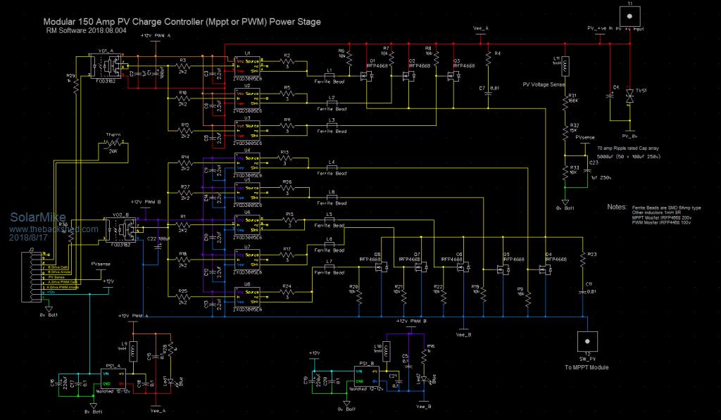 Cheers Mike |
||||
Chopperp Guru Joined: 03/01/2018 Location: AustraliaPosts: 1032 |
Hi Solar Mike, Had bit of a look at some of your schematics. Very impressive !!! Quick question. How are you actually going to mount / connect the ACS770 current sensor? I notice you have 150A PCB screw terminals listed. They would not be that small. Brian ChopperP |
||||
| Solar Mike Guru Joined: 08/02/2015 Location: New ZealandPosts: 1125 |
Hi Brian >>Quick question. How are you actually going to mount / connect the ACS770 current sensor? Legs will be bolted between 2 15x3mm thick copper bars mounted on the sense pcb, will straighten out their legs and use 5mm stainless screw bolts with copper washers tapped into the bar. Edit: I do have some 100 odd amp pcb screw terminals, but using all copper bars now for the high current connections. Mike |
||||
| Chopperp Guru Joined: 03/01/2018 Location: AustraliaPosts: 1032 |
Thanks Mike, I assume you are talking about straightening the high current leads. You weren't able to get the straight leg version? RS only shows the bent leg ones. Brian ChopperP |
||||
| Solar Mike Guru Joined: 08/02/2015 Location: New ZealandPosts: 1125 |
Correct, at least I hope they will straighten without wrecking them; no one seems to sell the straight leg versions, I purchased some of those bent leg ones on Aliexpress for about US$2 each. If that idea doesn't work I will try this 200 Amp Sensor, only problem is it requires +- 15v supply. Cheers Mike |
||||
| Chopperp Guru Joined: 03/01/2018 Location: AustraliaPosts: 1032 |
>> $2 US. Bit cheaper than RS I've been using these. They do require about 100mV or so which means a fair bit of power dissipation in a shunt at high currents, but you can have the sensor remote from main power circuit. They are powered from the circuit being monitored so if that goes below about 5V, (e.g. , power supply output), you lose the monitoring. Thinking maybe yours are better in some ways. Much lower dissipation & separate power supply. (Just thought of a way I may be able to overcome the low voltage drop out problem. More thinking required ..)Have fun Brian ChopperP |
||||
| Warpspeed Guru Joined: 09/08/2007 Location: AustraliaPosts: 4406 |
You could try the Allegro ACS758 series of Hall sensors. Single supply +5v and up to 200 Amps. https://www.allegromicro.com/en/Products/Current-Sensor-ICs/Fifty-To-Two-Hundred-Amp-Integrated-Conductor-Sensor-ICs.asp x Cheers, �Tony. |
||||
| Warpspeed Guru Joined: 09/08/2007 Location: AustraliaPosts: 4406 |
Just realised the Allegro type of sensors are what you are using anyway, DUH ! Always possible to solder lugs onto the sensor, and then bolt the whole thing in position with a three pin socket and cable for the thinner legs. The whole problem of a very high power solar controller are vexatious. I get around this myself, by running my inverter directly from the solar panel voltage, this provides a much higher power efficiency and there is much less to go wrong. All that is then required is a smart solar controller of much lower power capability to charge the battery. Its all built around a suitably large bridge rectifier plus heat sink. The fourth diode is obviously still there, but does nothing. Its drawn the way it is to make the whole thing more easily understood. You may need to think about this for a while. It totally changes how the the whole system and each part of it works day/night, and what each part of the system needs to do. This would be more appropriate if anyone is planning a higher dc voltage system. 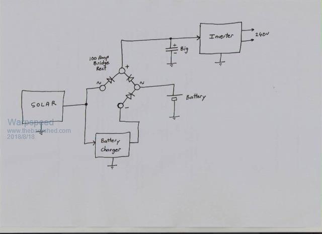 Cheers, �Tony. |
||||
| Solar Mike Guru Joined: 08/02/2015 Location: New ZealandPosts: 1125 |
Agree, wish it was easier, straight off the PV panels with a bang bang switch sensing battery charge voltages would be the simplest, easier with higher voltage systems and matching panel voltages. I'm only making a dual type of controller as I have multiple PV setups and would rather have something that can be used for both, and not using a commercial product with its built in obsolescence that no one can repair when it blows up. Latest power board pcb. 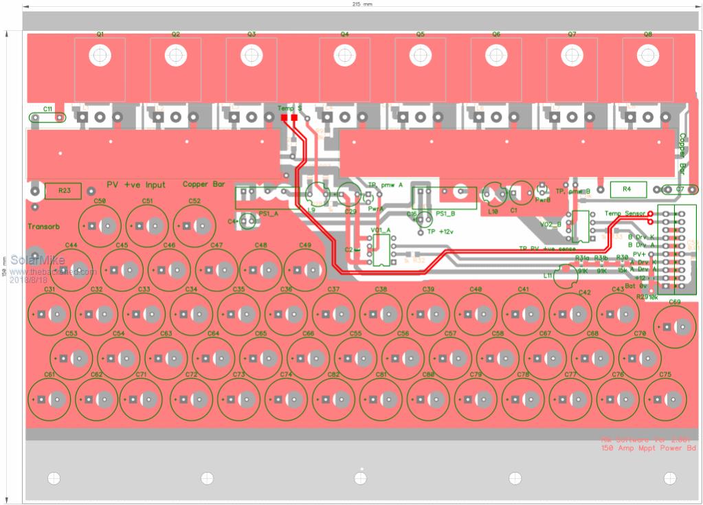 Cheers Mike |
||||
Madness Guru Joined: 08/10/2011 Location: AustraliaPosts: 2498 |
Mike I am sure you have looked at it, my regulator with PWM on both DC panels and regulating Grid Tie Inverters works really well. Great thing about GTI's is all the MPPT is built in and you can use any sort of panels. That is providing you have an Inverter that is compatible with GTI's and back charging. There are only 10 types of people in the world: those who understand binary, and those who don't. |
||||
| Solar Mike Guru Joined: 08/02/2015 Location: New ZealandPosts: 1125 |
Yes I have and it would be a good solution, however there is no second hand market here in NZ for GTI's or any other grid tied inverters for that matter, so none to be found at a good price.  |
||||
| Madness Guru Joined: 08/10/2011 Location: AustraliaPosts: 2498 |
Surely freight from Australia for secondhand ones on Ebay would not be too much? Or Gumtree, usually cheaper than Ebay, HF type like the Zeversolars I am using are not real heavy. There are only 10 types of people in the world: those who understand binary, and those who don't. |
||||
| Solar Mike Guru Joined: 08/02/2015 Location: New ZealandPosts: 1125 |
Gumtree perhaps, will look into it, have looked on Ebay a few times, prices seem expensive $500 + for second hand units, freight $100 approx. then there is GST and customs import fees, not really worth it... |
||||
| Solar Mike Guru Joined: 08/02/2015 Location: New ZealandPosts: 1125 |
Meanwhile I have made progress on the synchronous rectifier, my original circuit a few posts back was using a current sensor chip + comparator to detect when reverse current was flowing in the primary buck inductor from the battery bank and switch off the synchronous mosfets; as in these conditions if left would create a boost voltage with a lot of energy. Typically this could occur when the main buck mosfets were switched with a low duty cycle, eg at times of battery float. In a normal buck power supply this situation wouldn't matter too much as the energy of any boost was limited by the size of the output cap and would be absorbed back into the main buck capacitors. However with a battery load, there is no limiting condition until something goes bang. So having decided that the synchronous switch should turn itself off autonomously independent of its controller, then why make it dependent on the controller at all, to that end I have altered the circuit to use a smart rectifier synchronous controller ic, chosen the IR1672, mainly because I have a dozen or so here waiting for a use. These tiny 8 pin chips sense the voltages between the drain and source pins of the mosfets and make the decision when to turn the mosfet on and off; assuming they make the correct choice it should work and solve any issues with reverse boosting. As their gate drive output is limited to 2 amps, have decided to leave the driver chips in circuit. 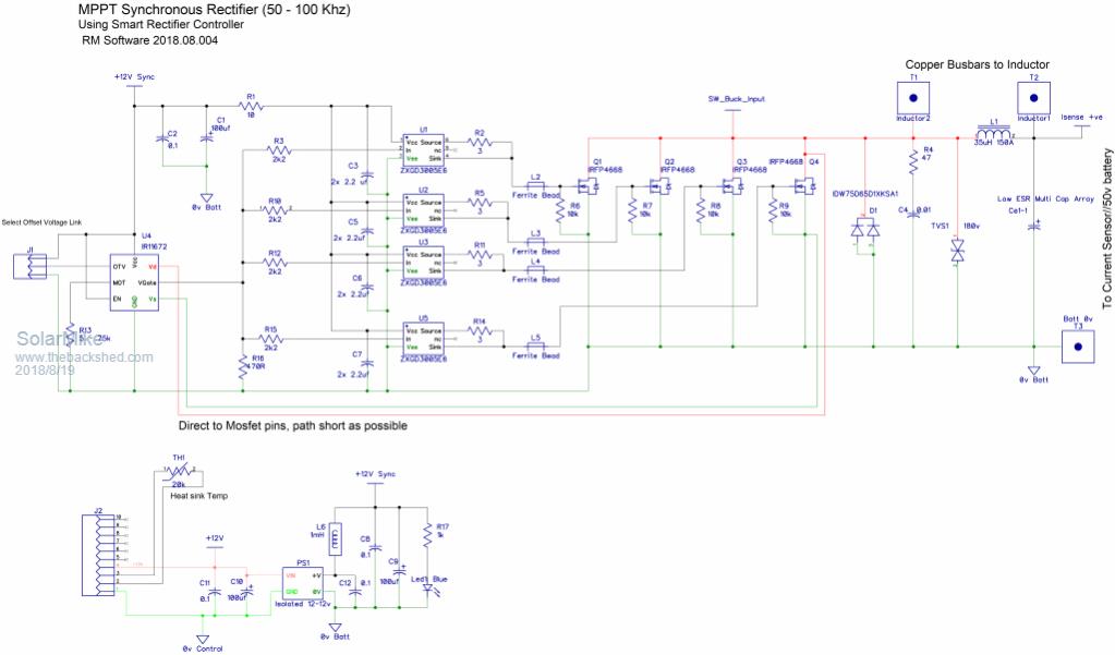 Due to the very high currents involved here their power supply is isolated so a single point earth can be used to keep any noise etc off the chips 0 volts rail. Cheers Mike |
||||
| Warpspeed Guru Joined: 09/08/2007 Location: AustraliaPosts: 4406 |
Very nice Mike. These smart rectifier chips are something relatively new that I had not seen before, and there seem to be a variety of them out there from different manufacturers. I will definitely look a bit deeper into those, they look really interesting. Always something new to learn about. Cheers, �Tony. |
||||
| Solar Mike Guru Joined: 08/02/2015 Location: New ZealandPosts: 1125 |
There is so much new stuff out there its impossible to keep up with it. Here is the Data Sheet IR11672 if anyone is interested, certainly makes it easier as now I don't have to worry about creating a half-bridge driver with dead time, will modify the previous driver module design next. Mike |
||||
| Solar Mike Guru Joined: 08/02/2015 Location: New ZealandPosts: 1125 |
Right, modularization of the charge controller continues with the current sensor; as this module is useful for multiple designs have made a pcb for it, uses the Allegro ACS770 series Hall-Effect based sensor chips, these come in various current ranges with "U" types unidirectional and "B" types bi-directional, sensitivity output depends on the current range. The one I'm using (150B) requires a certain thermal mass to act as heat sinking for the 2 heavy copper legs, rather than attempt to solder to the copper bars its easier to straighten the legs with pliers (easy to do) and bolt the device to the copper bar carrying the current using 4mm stainless bolts; this is like a crimp connection and will have low resistance with no issues with solder crystallization. Personally I wouldn't attempt to use these above 150A, higher currents are better sensed with the pass through Hall-Effect sensors using a heavy copper bar or cable. 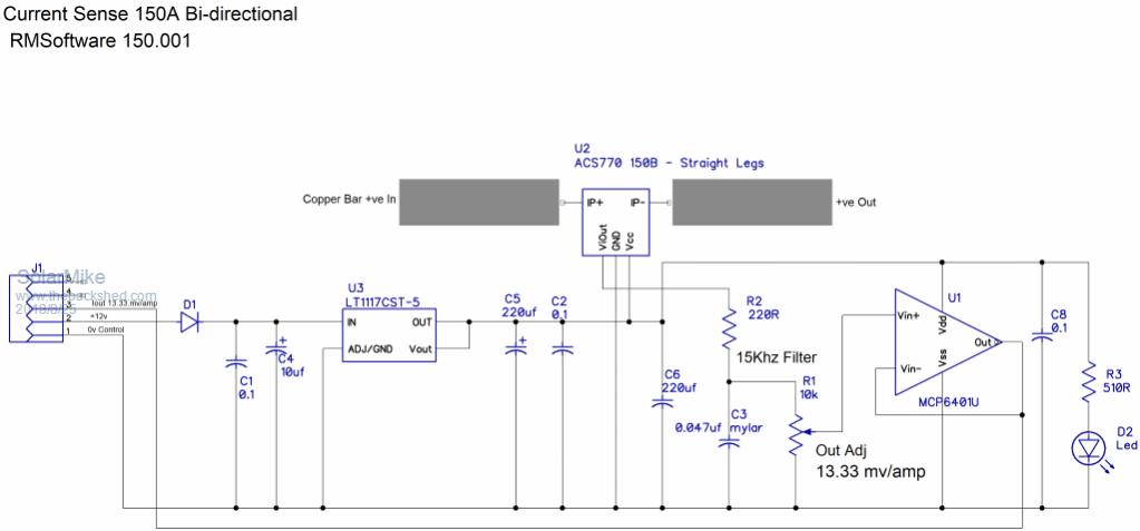  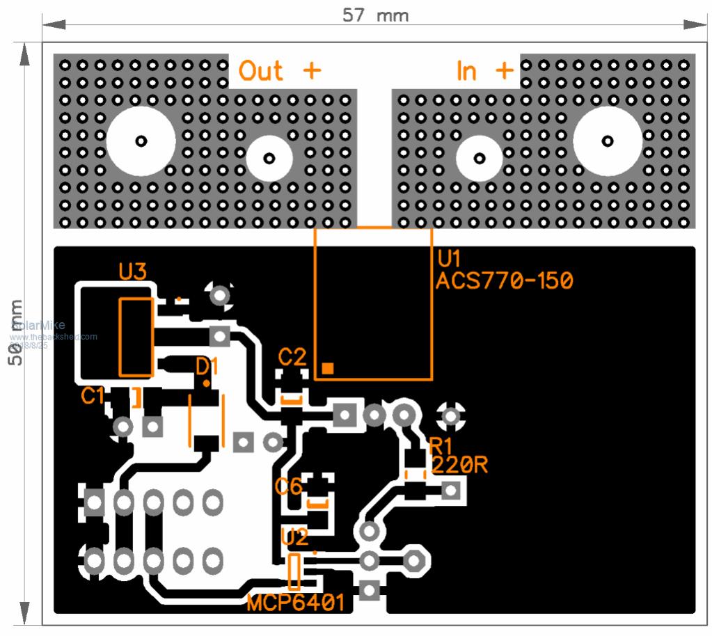 Cheers Mike |
||||
