
|
|
Forum Index : Electronics : A newbie ozinverter build
| Author | Message | ||||
| noneyabussiness Guru Joined: 31/07/2017 Location: AustraliaPosts: 506 |
Im with poida.. also if you want, bypass the internal bridge rectifier, theres a volt or 2 extra to start the chip up... I think it works !! |
||||
| tinyt Guru Joined: 12/11/2017 Location: United StatesPosts: 430 |
Was reading on AC skin effect on copper in one of the AWG chart in the web, it shows that at 21KHz the 100% skin depth is 0.91186/2 mm or 0.0359/2 in. So, it seems that to make effective use of the copper wire(s) for the windings, they should be stranded or (x-in-hand). And the diameter of each wire strand should not be larger than 0.91186mm or 0.0359 in. Should this be observed? 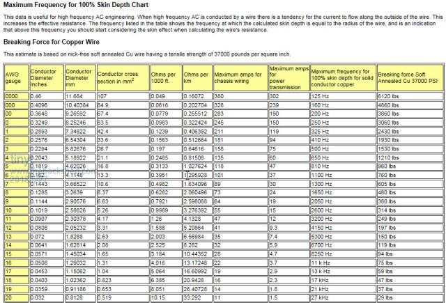 |
||||
| Warpspeed Guru Joined: 09/08/2007 Location: AustraliaPosts: 4406 |
Yes that is quite right about the skin depth, the actual formula is 66 divided by the square root of the frequency in Hz. Skin depth works out to 0.43mm at 23.4 Khz, and the optimum wire diameter will be twice that. But if your series choke in the primary is working properly, neither the choke or the transformer will have any significant current flowing at 23.4 Khz. There should only be a sine wave current at 50Hz there. So you can forget about the skin effect problem altogether. If you decide to be very brave and run without a series choke in the primary, then you are going to have problems of excessive heating from skin effect. Cheers, �Tony. |
||||
| tinyt Guru Joined: 12/11/2017 Location: United StatesPosts: 430 |
I tried the approximation formula found in wiki:  And I came up with a skin depth of 0.449 mm for 21KHz. I think the 0.449 mm is the radius, so the diameter is twice that or 0.9 which is close to what the chart says. And should the multi-strand also apply to the secondary (230VAC)? |
||||
| Warpspeed Guru Joined: 09/08/2007 Location: AustraliaPosts: 4406 |
I edited my post after you posted. Skin depth only applies to current flow, its a magnetic phenomenon. If you have significant series inductance, there can be a lot of very high frequency voltage present, but a very low high frequency fluctuating current. And its the current that creates the skin effect (and the excessive heating). Cheers, �Tony. |
||||
| Warpspeed Guru Joined: 09/08/2007 Location: AustraliaPosts: 4406 |
The skin effect is a gradual reduction in current density with depth. There is no actual precise total current cutoff depth, its an approximation that agrees with practical testing. So do not be too surprised if different methods of reaching an approximate number for skin depth vary after the first couple of digits. Its not a precise number just a useful indicator and guide. Cheers, �Tony. |
||||
| Warpspeed Guru Joined: 09/08/2007 Location: AustraliaPosts: 4406 |
If you were building a transformer to have 23.4Khz on the primary, and expect to see the exact same 23.4Khz across the secondary (but at a different voltage) then the whole transformer, primary, core material and secondary all need to be designed to efficiently work at 23.4Khz. If you are building a 50Hz sine wave inverter, it makes much more sense to use a choke in series with the primary, then the whole transformer, primary, core, and secondary only ever see a 50Hz sine wave. And you can forget all about the skin effect problem. Even the choke can be wound with solid wire. Cheers, �Tony. |
||||
| tinyt Guru Joined: 12/11/2017 Location: United StatesPosts: 430 |
I am now working on the toroid and I thought I have to use lots of small gage wires even for the secondary. So, I don't need to un-wind the secondary and I might also be able to re-use the existing primary wires. Thanks Tony. |
||||
| Warpspeed Guru Joined: 09/08/2007 Location: AustraliaPosts: 4406 |
Yup. Its just a plain vanilla 60Hz transformer. But it will need to have a non saturating series choke in the primary of sufficient inductance to reduce the high frequency ripple at the PWM frequency. The choke can be wound from the same solid wire used in the primary. When you look at the waveforms on an oscilloscope, you will see a pretty violent high frequency dog's breakfast of PWM on the bridge end of the choke. On the transformer end, there should be a clean sine wave with just a slight thickening of the trace around the zero crossings. And your transformer will love it ! Cheers, �Tony. |
||||
| tinyt Guru Joined: 12/11/2017 Location: United StatesPosts: 430 |
Started working on the datatel elektronik toroid. It has the following ratings: 153V 50-60Hz, 230V/9.6A. (2.2KVA?). Using a variac and temporarily wound 20 turns, I calculated that it has 1 turn per volt winding. Started de-mummifying: 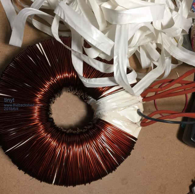 The 153 vac outer winding is 2 in hand awg #12, followed by an electrostatic shield and finally the single layer 230 vac awg #11. I removed the outer and shield windings and retained the inner 230 vac winding. Applying 100 vac to the 230 vac winding, I located the center tap by looking for the mid-voltage with a voltmeter connected to one end of the winding and the other voltmeter probe attached to an X-acto knife blade. With the sharp tip of the blade, I poked thru the insulation of the magnet wire looking for a mid-voltage reading. The center tap measured 50 vac, but the wire beside it measured 99 vac. I think the winding is split-return type as the center-tap is close to the start/end of the winding. See picture. 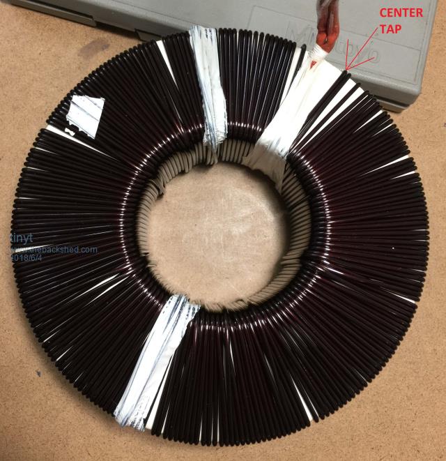 I cut the center tap giving me 2 isolated and equal voltage windings which I can configure for 115 vac or 230 vac. For 115 vac, I will connect the two in parallel. I guesstimate that the core has the following dimensions: ID = 3.5"(89mm), OD = 7.5"(190mm), HT = 2"(50.8mm) giving a core cross section of 2" x 2" = 4 sq. in. (2580 sq mm), maybe my estimated dimensions are a little bit conservative. The toroid ID with its exposed 230 vac winding is about 3.125"(79mm). If I add the 26 vac winding now, there will be a lot of wasted space in the toroid ID. So I plan to add another layer(s) of two 115 vac windings and adjust the cross section area of the 26 vac wire. I used a variac and measured the no load current draw at various voltages: VAC No Load Current Watts 190 0.043 8.17 200 0.048 9.6 210 0.055 11.55 220 0.055 12.1 230 0.055 12.65 240 0.056 13.44 250 0.064 16 260 0.064 16.64 270 0.065 17.55 280 0.066 18.48 289 0.071 20.52 So, I am guessing that the core will be able to handle higher power output than 2.2KVA before saturating. The 60 Hz instead of 50 Hz will probably also help. |
||||
Madness Guru Joined: 08/10/2011 Location: AustraliaPosts: 2498 |
I have a single core with similar dimensions but 70MM high, it runs fine at 4KW with cooling, you can probably expect around 3KW. There are only 10 types of people in the world: those who understand binary, and those who don't. |
||||
| Warpspeed Guru Joined: 09/08/2007 Location: AustraliaPosts: 4406 |
Saturation only occurs if you apply too higher a voltage, together with too few turns. It has nothing to do with current or power output. Flux density remains constant from zero load to maximum load. Output current is limited only by heating of the wire, thicker wire allows more current and gives a higher power capability. A reasonable guide to current capability would be about four amps per square millimeter of wire cross sectional area. I am guessing here, but assume 1.8mm diameter wire. Pi R squared = 3.142 x 0.9 x 0.9 = 2.54 mm area. 2.54mm area x 4 amps = 10.16 amps 10.16 amps x 230v = 2.337 watts. Cheers, �Tony. |
||||
| tinyt Guru Joined: 12/11/2017 Location: United StatesPosts: 430 |
Thanks for the info. Except for the HVAC, our entire house can probably be off grid most of the time with 3KW. In ebay I found this 3000VA core which has the same dimension that I measured. |
||||
| tinyt Guru Joined: 12/11/2017 Location: United StatesPosts: 430 |
Thanks for the clarification on saturation. From the wire table, the existing awg #11 230V winding is 4.17 sq.mm. So, it is capable of around 16.68 amps. So if I re-use the awg #12 outer winding that I removed for an additional 230V winding, the 3.31 sq. mm will potentially add 13.24 amps capability for a total of 29.92 amps or 6.8 KW, might not be achieved actually but good to know. |
||||
| Warpspeed Guru Joined: 09/08/2007 Location: AustraliaPosts: 4406 |
If you can actually squeeze all that wire onto the core, it should be capable of that power. Its why commercial transformers are always full. Cheers, �Tony. |
||||
| tinyt Guru Joined: 12/11/2017 Location: United StatesPosts: 430 |
I still have not added the 230v (2x 115v) winding as I need to straighten the harvested wires. Meantime I added a 10K ohms thermistor bead. 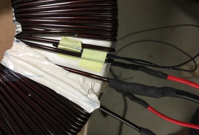 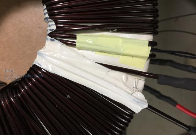 It should give a more accurate toroid temperature I hope. |
||||
| tinyt Guru Joined: 12/11/2017 Location: United StatesPosts: 430 |
My order came, they now added a heatsink covering the mosfet and power diodes. New DC-DC . When ordering, I had to attach a message to specify the 17.6VDC output. Referring to the schematic I posted earlier, for the 17.6VDC version, R7 and R8 are 150K ohms and R7A and R8A are 3.3K ohms. The schematic shows Z1 as a zener diode, but it tested like a regular diode, removed from the board I went up to 30VDC thru a series resistor, but I measured also 30VDC across the diode. I then tested one unit at 63VDC input with two different loads: Input Current(A) Load Current(A) Output Voltage(V) Input Watts Output Watts Efficiency % 0.002 0 17.78 0.126 0 0.1 0.33 17.8 6.3 5.84 93.2 0.45 1.6 16.8 28.35 26.88 94.8 I did not do temperature measurements but based on the high efficiency, I think it is going to run cool. I measured the magnet wire they used for the toroid and it is awg #22 (0.645mm dia.). I will see if I can replace the wire with multiple strands smaller diameter with a larger total cross section area and hopefully I can lower the voltage drop at high load current. But I like this better than the LM2596HVS DC-DC. I know I am spending a lot of effort for this Chinese thing, but it is the one I am going to use on my inverter and it is good to know how it will perform. |
||||
| tinyt Guru Joined: 12/11/2017 Location: United StatesPosts: 430 |
Did the toroid wire change to 5 strands awg #26. No change in voltage drop. Tested another one still at 63vdc input. Input Current(A) Load Current(A) Output Voltage(V) Input Watts Output Watts Efficiency % Not measured 0 17.70 0 0.57 2.04 16.54 35.91 33.74 93.96 0.74 2.69 16.37 46.62 44.03 94.45 I am satisfied with this and will be moving on. |
||||
| tinyt Guru Joined: 12/11/2017 Location: United StatesPosts: 430 |
Started to solder awg #10 wires for the transformer connection. The black heatshrink is to prevent the strands from spreading out during soldering. 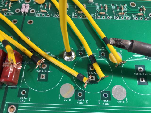 Doing the bottom for the battery wires. Notice the creepy crawlies coming out of the holes. 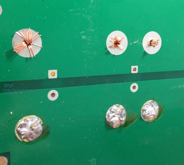 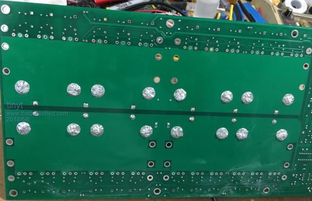 Top view shows the forest of wires, all of them are awg #10 (2.588mm, 5.26 sq.mm). 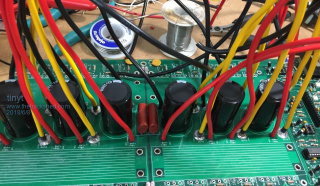 So for the 6 group of the yellow wires for each of the transformer primary connections, the total cross section is 31.56 sq. mm, equivalent to 6.34 mm dia.(awg #2) The battery wires are 8 each ( 8 red for +, 8 black for -), the total for each polarity is 42.08 sq. mm, equivalent to 7.32 mm dia. (awg #1) |
||||
| tinyt Guru Joined: 12/11/2017 Location: United StatesPosts: 430 |
Added more awg #10 wires. Drilled new holes for the battery wires with the top counter sunk to prevent shorting the top and bottom layers during soldering. 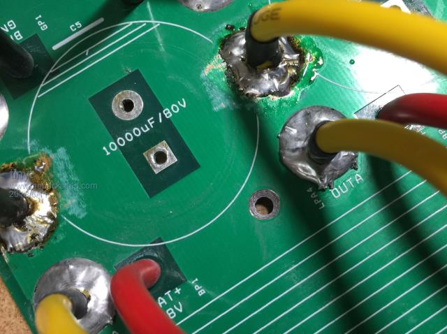 Yellow wires for tranformer connections are now 9 and the battery wires are now 12 for each polarity. 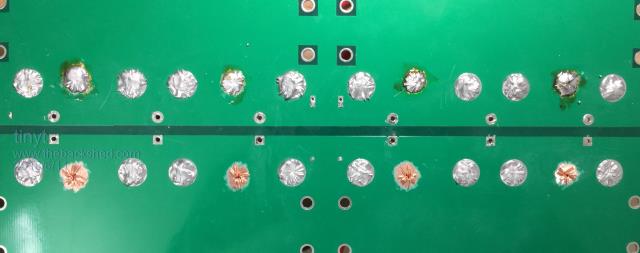 So the equivalent cross section areas are: Yellow transformer connections: 5.26 mm x 9 = 47.34 sq. mm or 7.7 mm dia. (between awg #1 and #0) Battery connections each polarity: 5.26 x 12 = 63.12 sq. mm or 8.96 mm dia. (between awg #0 and #00) I re-used the white insulating tape that I un-wound earlier and used my wife's flexible measuring tape to approximate how long each turn of the first layer will be. 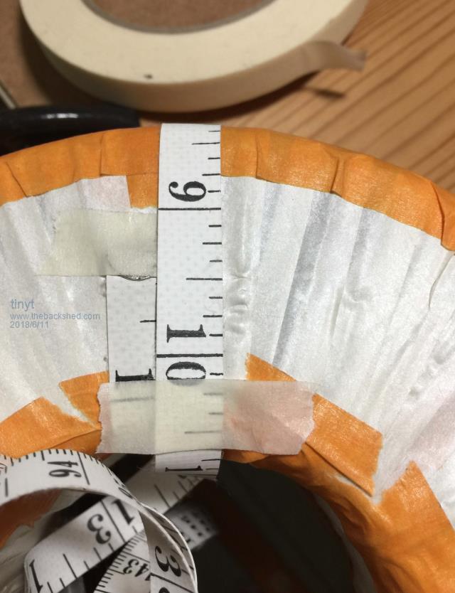 The toroid ID for the added first layer is about 2.9 inches (73.66 mm). I sketched in autocad the layers and found out that if I re-use the awg #12 that I un-wound earlier, the primary will not fit. Since I have awg #14 left over from an earlier project, maybe I can use it. From the wire table, this makes the equivalent cross section area of the 230vac wire to be 4.17 + 2.08 = 6.25 sq. mm. The primary should have 9 x 6.25 = 56.25 sq. mm or 8.46 mm. dia. (0.333 inch) I re-drew the sketch with the new dimensions and looks like everything will fit (I hope). 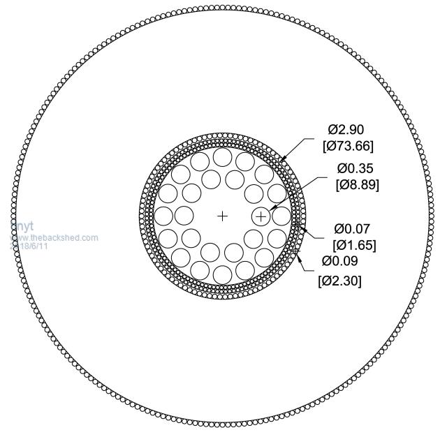 So I am now loading on the bike tire rim the awg #14 wire. I might have to buy more for the second 115vac winding. 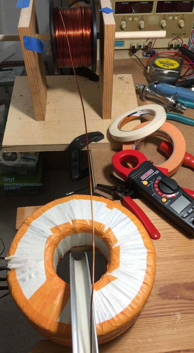 |
||||
