
|
|
Forum Index : Electronics : Inverter PCB�s
| Author | Message | ||||
Madness Guru Joined: 08/10/2011 Location: AustraliaPosts: 2498 |
Try this download. There are only 10 types of people in the world: those who understand binary, and those who don't. |
||||
renewableMark Guru Joined: 09/12/2017 Location: AustraliaPosts: 1678 |
  That worked fine Mad, but....... that's the GTI software, I needed the inverter control board software. Edit, btw I tested this with an unfinished board, Mad said it just needed the bits on the left to test the arduino. Cheers Caveman Mark Off grid eastern Melb |
||||
| Madness Guru Joined: 08/10/2011 Location: AustraliaPosts: 2498 |
I thought you already had the sketches as posted on here, anyway I have attached them for you.2018-08-04_082213_Inverter_Control_Board_Sketches.zip First use the DS1820 to get the addresses of your temperature sensors, you will need to open the serial monitor in the Arduino software. after you have them you need to enter them into this part of the control board sketch. DeviceAddress Probe01 = { 0x28, 0xEE, 0xDC, 0x17, 0x2E, 0x16, 0x01, 0x9D }; // Address for the Sensor connected to Heatsink DeviceAddress Probe02 = { 0x28, 0xEE, 0x2E, 0xE1, 0x1C, 0x16, 0x01, 0x51 }; // Address for the Sensor connected to Toroid So if you get 28 EE DC 17 2E 16 1 9D it becomes 0x28, 0xEE, 0xDC, 0x17, 0x2E, 0x16, 0x01, 0x9D Note the second last value was 1 needed to become 01 There are only 10 types of people in the world: those who understand binary, and those who don't. |
||||
| renewableMark Guru Joined: 09/12/2017 Location: AustraliaPosts: 1678 |
Thanks mate I'll look at it tonight, have to catch up on work today. Also when you get a chance could you put up a link for the control board transformer you use? It looks like a much more tidy than how I did my last one. Cheers mate. Cheers Caveman Mark Off grid eastern Melb |
||||
| Madness Guru Joined: 08/10/2011 Location: AustraliaPosts: 2498 |
PCB Mount Transformer There are only 10 types of people in the world: those who understand binary, and those who don't. |
||||
| renewableMark Guru Joined: 09/12/2017 Location: AustraliaPosts: 1678 |
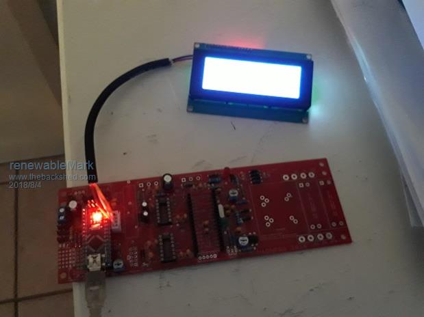
Finished work earlier than expected. Got it done. Did have a problem though, it came up with errors due to a conflicting multiple liquid crystal, so deleted the library completely, re installed still had the error, took off just liquid crystal and tried to load sketch, it said library missing, added it again and it said multiple conflicting libraries. Went into program files 86 on c drive and found arduino and deleted the onboard liquid crystal then went to load the control board software and BINGO. Did the addresses for the temp probes, had one error as I didn't put in a comma, then another error due to an O instead of a 0, in the program they don't have a line through the middle, just look a different shape, so be aware of that. Also the pins on the control board are not pin for pin on the back of the lcd. On control board top is grd then pos then SCL then SDA. so the bottom two are the other way around to what is the order on the back of the lcd. Pic shows the colours for wiring. BTW that was some sheilded 4 ply available from jaycar (and yes I will shrinktube the ends to prevent melal fibres coming loose) 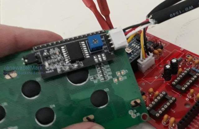  So if I can do it anyone can! Cheers Caveman Mark Off grid eastern Melb |
||||
| Madness Guru Joined: 08/10/2011 Location: AustraliaPosts: 2498 |
Well done, yes it is not that difficult and if you had to do it again it would be quite straightforward. Also a good idea to leave the tape on the top of the beeper till you are ready to put it into use properly as it is rather loud otherwise. BTW I have all boards available if anybody is wanting anything. There are only 10 types of people in the world: those who understand binary, and those who don't. |
||||
| renewableMark Guru Joined: 09/12/2017 Location: AustraliaPosts: 1678 |
LOL I was a bit worried about it but it was in fact easy. Funny thing was the GTI sketch loaded fine without any alterations, but the built in liquid crystal had to be removed from program files for the control board to load (in my case). Has anyone else had that problem? Has anyone got that far yet? Cheers Caveman Mark Off grid eastern Melb |
||||
| Madness Guru Joined: 08/10/2011 Location: AustraliaPosts: 2498 |
Yes it is quite easy in spite of what has been said previously. There are only 10 types of people in the world: those who understand binary, and those who don't. |
||||
| renewableMark Guru Joined: 09/12/2017 Location: AustraliaPosts: 1678 |
While I'm at it Mad, if you were to add the caps like Oz did on my Clockman board how would you incorporate them on your board (it's a different layout). Cheers Caveman Mark Off grid eastern Melb |
||||
| Madness Guru Joined: 08/10/2011 Location: AustraliaPosts: 2498 |
Just put them from EG8010 pin 6 or the middle pin of the switch connector to ground use a 104 & a 106. There are only 10 types of people in the world: those who understand binary, and those who don't. |
||||
| renewableMark Guru Joined: 09/12/2017 Location: AustraliaPosts: 1678 |
Mad, I'm almost done building the gti controller, the last bit arrived yesterday. Can you clarify the instructions for the resistors? 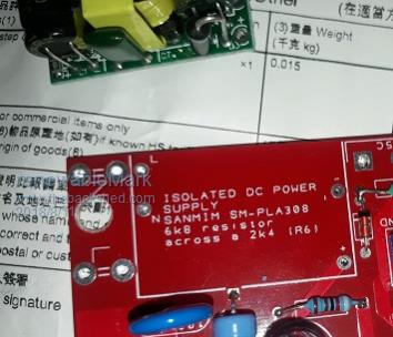 Cheers Caveman Mark Off grid eastern Melb |
||||
| Madness Guru Joined: 08/10/2011 Location: AustraliaPosts: 2498 |
On the DC side remove the large diode next to the + output. You need to take the diode out so you can bend up the Electrolityc capacitor, then you will see the surface mount resistor R6. As per the instructions on the PCB solder a 6K8 resistor across R6, the easiest way is to put another surface mount resistor on top of it but a 6K8 0.25 W through hole resistor does the job also. You need to bend one leg and back onto the resistor and then at 90 degrees so it so the 2 wires match the length of R6. Cut the wires so there is only 2 mm or so pointing down, tin them and then solder to R6. It is a bit fiddly but not that difficult, when done bend the big capacitor down and put the diode back in. Once done solder wires through the power supply to the PCB. The reason for this modification is to increase the output voltage to 18V. There are only 10 types of people in the world: those who understand binary, and those who don't. |
||||
| renewableMark Guru Joined: 09/12/2017 Location: AustraliaPosts: 1678 |
OK got that done. So the red arrows are for 240v mains in to feed the isolated supply yeah? Output should be 18V on the other side. Blue arrows are for Panel neg input/output and the pos line goes direct to gti input yeah? 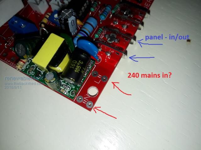 Cheers Caveman Mark Off grid eastern Melb |
||||
| Madness Guru Joined: 08/10/2011 Location: AustraliaPosts: 2498 |
Yes L & N are live and neutral for 240VAC, Yes positive from panels goes directly to the GTI PV negative in out are clearly marked just make sure you keep the 2 halves correct for each of those GTIs ypu are using or if you had a GTI with 2 channel inputs. 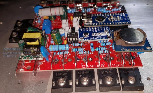 There are only 10 types of people in the world: those who understand binary, and those who don't. |
||||
| tinyt Guru Joined: 12/11/2017 Location: United StatesPosts: 431 |
Hi Mad, Just want to say that I received the regulator pcbs and parts today. Thanks for sharing your work to this part of the world. I don't have time yet to put them together. You will know when I start asking for help.  |
||||
| Madness Guru Joined: 08/10/2011 Location: AustraliaPosts: 2498 |
No problem just give us yell if need help. There are only 10 types of people in the world: those who understand binary, and those who don't. |
||||
| renewableMark Guru Joined: 09/12/2017 Location: AustraliaPosts: 1678 |
Hey with that isolated supply, what is the min voltage that circuit needs? Would a 15v input work like from this here I would like to avoid mains power on there if possible. My GTI's have a 70-100v dc range. So if 15v supply will work I can avoid any high voltage on the board/enclosure. Cheers Caveman Mark Off grid eastern Melb |
||||
| Madness Guru Joined: 08/10/2011 Location: AustraliaPosts: 2498 |
The PSU MUST BE ISOLATED that is why it has the one specified. You can get Isolated DC to DC ones but they are a lot more expensive. You MUST also ensure that the 4 High Voltage MOSFETs are isolated from the heatsink. There is no if's or buts about it, the GTI side of the regulator must be isolated electrically. There are only 10 types of people in the world: those who understand binary, and those who don't. |
||||
| renewableMark Guru Joined: 09/12/2017 Location: AustraliaPosts: 1678 |
OK would this work? Does it need 18v, I can't find one with that output. Cheers Caveman Mark Off grid eastern Melb |
||||
