
|
|
Forum Index : Windmills : Few starting out questions
| Author | Message | ||||
| BarkyJ Senior Member Joined: 26/04/2018 Location: New ZealandPosts: 114 |
Hi Dave I tried to delete the first post, but cant. I removed the image from my host, and its still there. I cant even edit the post now - which is really strange. I dont get your comment of me editing a perfectly good image, I am trying to figure out how to wire in delta, so whether I draw one from scratch or I modify one, putting on it here will have the same result if its incorrect. Maybe you are referring to my first image only, you might have started posting when that appeared, rather than after seeing my 2nd post? My 2nd image is correct, yes? If someone can delete the first image post, that would be appreciated. Thanks for the info on the blades etc. The materials I have allow me to make up to 1.5m, but if you think I should go smaller, then that is no problem. With dual stator 4x3C Delta, if I can start applying load from 20V, then that is all good. I assumed that if my load is enough to take all the power the windmill can generate, then it would have a similar effect as a battery in some ways, and I could essentially clamp the voltage to about 48VDC by simply raising and lowering the PWM, ie the load the stator sees. So what I am doing is achievable then? Did you aim to try and keep your voltage at a set level, or were you focusing on another parameter such as Power? You were clamping the voltage with the load I assume? Side question. The speed sensors on the F&P stator. I had assumed that with a 15VDC Powersupply, the output was going to be 15V pulses, however from what I can tell they are ragged looking TTL 5V pulse of sorts. So my current divider to reduce the voltage is wrong. The divider I have seems to load the sensor, and the output drops to about 500mV P-P, which is unusable. Even connecting it directly to my controller it is not happy and cant count the pulses. Are these designed to have a pull up or pull down on the output phase line, or is some other circuitry required to use it? Phase 2 output is better looking than Phase 1. Potentially this speed sensor is faulty, I have a few others I can try though. Attached is a pic of the output I see, unloaded. And then one of my test setup.   Thanks again |
||||
| BarkyJ Senior Member Joined: 26/04/2018 Location: New ZealandPosts: 114 |
Regarding mechanical furling, yes that is the plan. I still have to read up more on this subject, but I have seen videos of other peoples solutions, and then Gizmos plans for his single stator build. I have contemplated having a motor driven angle system, and using external wind direction sensors to point the windmill into the wind. If things get out of spec, have it turn out of the wind slightly or fully etc. But I am still thinking all this over. Regarding blade design, I am still to finalise this also, I put the pipe I have into Solidworks and have cut out a basic shape in software, and played with angles of cut to give the blades curve etc, but still yet to figure out if it will have any advantage or not. The exact shape is still very much to be finalised, that will come in time. I have enough material to cut a dozen blades, so I can make all shapes and sizes and experiment potentially. Thanks |
||||
| BarkyJ Senior Member Joined: 26/04/2018 Location: New ZealandPosts: 114 |
Phase 1 of the RPM sensor were spikes up to 5V, and this I was able to read, but it doesn't look right. Phase 2 is as above, squarish waves, but output seems very variable in terms of amplitude, sometimes going to 4V, often only getting to 2V, so this is not reliable for reading. Phase 3 is a lovely square wave, 5.5V P-P or so. So potentially Phase 1 and Phase 2 outputs are no good, but Phase 3 looks encouraging. I can read this one correctly.    |
||||
DaveP68 Senior Member Joined: 25/11/2014 Location: New ZealandPosts: 292 |
The drawing looks correct now. As per my photo of the 6x2C Delta I don't wire them the way you have drawn it. The reason for my wiring system is for electrical symmetry with all currents flowing equally, as all resistances are also equal (down to milliohms). As for the RPS waveform the phase 3 signal is what you're after. Remember I did say you only need 1 phase output to measure RPM. It's likely that RPS unit you picked to test is faulty as they have a high failure rate (1 in 4) in the field over time. I'm sure you have another RPS unit of the same type you can also try out. There are realities if you do not accept, will lead to frustration because you will be spending time on wrong assumptions and the results cannot follow! The Dunning Kruger Effect :) |
||||
| BarkyJ Senior Member Joined: 26/04/2018 Location: New ZealandPosts: 114 |
Hi Dave Yep I was only using 1 output, however the 1st two I tried were not looking great, however the 3rd one looks good, so am using that one. I have 2 more RPM sensors so might change one out, as if this one has 2 failed channels then likely the 3rd wont be far away. I will try and study your picture some more for the balanced wiring, however really struggling to see the detail at that resolution. I think I get the idea of what you are talking about though. Would love to hear more about your 'solution' to the torque problem, and the external modifications. Thanks |
||||
| BarkyJ Senior Member Joined: 26/04/2018 Location: New ZealandPosts: 114 |
Just wanted to share a test I did. This is still the same Star 2x6C stator, 36 pole with black cap. So I have a test load of 26ohm on my FET, PWM controlled to attempt to maintain a voltage around 32VDC at this stage. You can see in the video as I increase the speed the voltage comes up to set point and then load then starts to increase. RPM continues to increase, as does load, as done current and power, until near 100% load. So this test works, however I dont believe it to be the best way to get the most amount of power, based on previous posts. Here is the video: https://youtu.be/GVbN3XEnHKU So Dave, based on what you were saying. If I do 4X3C Delta, then in theory I can start adding load from about 20V at about the 110-140RPM mark. Peak power will then be around 45V at around the 500RPM mark. Have I understood that correctly? If I then do dual stator, both 4x3C Delta, at 110-140RPM around 20V, I should expect to see 1 to 1.5A, and then 500RPM around 45V, I should expect to see around 22A. Correct? With my current Star 2X6C configuration, I would expect peak current to be around the 2.9A mark before the stator starts saturating, and if I am limited to 45VDC then my peak power is only going to be in the 100-200W range, so really its not an ideal configuration for what I want to achieve. Correct? So I should rewire to Delta 4x3C and then continue my testing with the controller to instead of controlling to a set voltage (32VDC in the video), I should try and control power based on RPM and voltage, in order to make the most out of the power produced. I hope I have grabbed the correct pieces of information there, as this sounds really good. |
||||
| DaveP68 Senior Member Joined: 25/11/2014 Location: New ZealandPosts: 292 |
Good progress so far and did also watch the YouTube video. You keep stating the term fixed voltage. That's not the end game as such and I do understand the power MOSFET is limited to 60 V max. Here is what I pointed out on page 3 of this topic which you may have missed. You should be safe to let the working voltage rise to a maximum of 55 VDC if required to keep everything under control. The cut in voltage is expected to be around 20 VDC and you should be able to take 1 to 1.5 Amps at that point without stall the blades. The 45 VDC at 22 Amps is an expected high end set of numbers but doesn't mean it will be it's maximum output, that is dependent the upper wind speed. This is a graph of Torque vs RPM on a set of GOE 222 blades 3 m diameter TSR 5.7 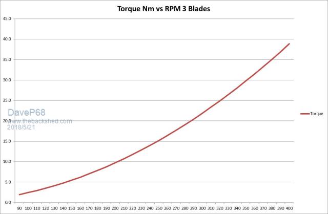 Note the Torque range is from around 2.5 Nm all the way up to 39 Nm. I suspect your blades will have a higher TSR of 7 to 7.5 so upper RPM will be around 500 with Torque being about 25 Nm. Here is another graph of Wind Power vs RPM, note the RPM is linear and the power follow the cube law of the wind speed. 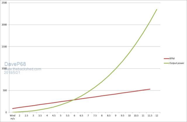 This is exactly what MPPT is trying to achieve. On a separate note you asked about how to boost the power output of F&P stators. This can be done using resonance capacitors and is best done on at high voltage to keep the capacitor size to a minimum. Capacitors I've used in Delta mode, 3 sets of 6 uF (12x 0.47 uF) AC rated at 305 V. 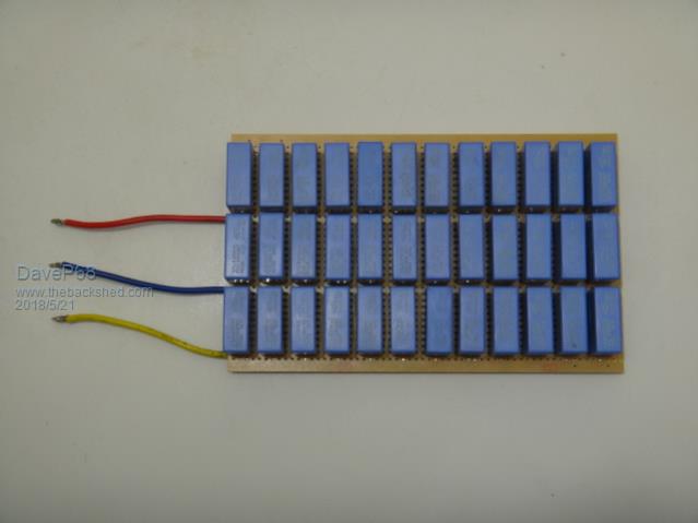 A graph of the difference in power output with them added 852W at 375 RPM and without 390 W at 375 RPM. 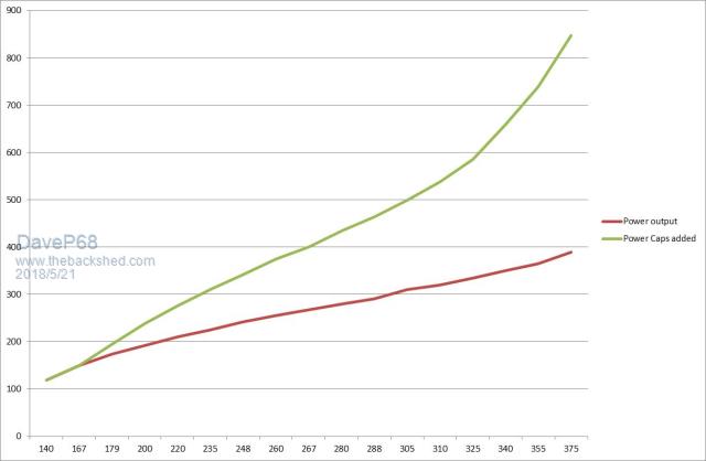 The resonance capacitors over double the output power by increasing the working voltage. They also over double the amount of torque the stator can take. There is a small drop in output efficiency but that is of no concern at they only operate at high power levels where there is power to burn  At low to medium power levels the stator efficiency remains > 80 %. There is a catch, if the RPM is able to go to high and go past the peak resonance point the Torque will start to drop off again. The idea is to always stay on the low side of peak resonance which can provide up to a 2.75 times gain in power. Plenty of head room to stay safe anyway. There are realities if you do not accept, will lead to frustration because you will be spending time on wrong assumptions and the results cannot follow! The Dunning Kruger Effect :) |
||||
| BarkyJ Senior Member Joined: 26/04/2018 Location: New ZealandPosts: 114 |
Dave, sorry more questions. I have mapped out your photo now, and I get what you have done - finally. However for 4x3C I am unsure how the pattern goes. Around yours, following your wiring colours, you go: RED, BLUE, YELLOW, YELLOW, RED, BLUE - all the way around, where RED goes to RED, YELLOW goes to YELLOW, and BLUE goes to BLUE (in the coloured wires). I can see the copper is swapping phase colours as you explained - that is all good. For 4x3C, what is the colour pattern equivalent as you go around? Thanks |
||||
| BarkyJ Senior Member Joined: 26/04/2018 Location: New ZealandPosts: 114 |
Wow Dave, thanks for that last post. I will read that a few times and absorb it all. Your cap system, is that something similar to what is on here, or quite different? https://www.thebackshed.com/windmill/articles/GordonsCapMod.asp These caps you connect to the 3 phases of the stator, before the rectifier I am guessing, and are connected all the time yes? I wont do this immediately, but it sounds truly awesome how you are making the most of this. Are they something like this? https://www.aliexpress.com/item/Free-Shipping-10PCS-NR3010-180M-18UH-3010-SWPA3010-SMD-Glue-inductance/32785406144.html You have them wired in Delta you said? Can you take a photo of the back of the board? Very interested :) Going back to your comment above about the voltage. If my 60V FET's are going to be an issue here, I can look for something with a higher rating. I guess my concern is just handling what comes out and putting it to work. What would be the peak voltage ideally that you think this would output, and have you used this directly into a resistive load, or would it be best to put this into an inverter or something which can take a range of input voltages? As mentioned I just want to dump into hot water to start with, but going into something like an inverter would be very neat down the track. Then if you add your Capacitor setup into the mix, the output voltage would go up even higher, so Im guessing the answer will be that I should hunt for a better FET or IGBT etc... Now to read your post a few more times and figure out what my next move is. Thank you so much for sharing all this |
||||
| DaveP68 Senior Member Joined: 25/11/2014 Location: New ZealandPosts: 292 |
Camera failed the other day that I usually take photo's with. The wiring isn't in a ring as per your drawing, that's only done on Star configurations not Delta. the Delta wiring per set "each of 2x poles" loop from R-B, B-Y, Y-R. Then each group of 6x sets of 2 coils is then "all wired in parallel" to the termination point. Carefully look at the picture and it will become clear to you. Go high voltage AC with a Delta 1x12C stator wiring problem solved... There are realities if you do not accept, will lead to frustration because you will be spending time on wrong assumptions and the results cannot follow! The Dunning Kruger Effect :) |
||||
| BarkyJ Senior Member Joined: 26/04/2018 Location: New ZealandPosts: 114 |
Hi Dave Yes I was referring to your photo in my statement. I know its not in a ring like the drawing I did is. I am referring to your photo and the wiring colours as you go around the outside, not of the poles themselves. So when you go around the outside of your photo, the WIRE colours you have used go R, B, Y, Y, R, B and then repeat. When looking at the original pole colours, I can see its R-B, B-Y, Y-R like you said. My question is, what is the configuration when its in 4X3C Delta instead? Does each set of 3x poles loop from R-B-Y, B-Y-R, Y-R-B this time? or something like that? I can see how your photo is wired, I just am not sure how it translates into 4X3C delta now. Sorry I dont understand what this is referring to. Thanks |
||||
| BarkyJ Senior Member Joined: 26/04/2018 Location: New ZealandPosts: 114 |
Ok I think I have clicked as to how to do it... I think. Drew it by hand using a blanked template. The colours didnt scan that well sorry of the hand drawn wires, but I hope its visible enough. Click on the image to make it bigger:  Can you please confirm if this is correct. Thanks |
||||
| Gizmo Admin Group Joined: 05/06/2004 Location: AustraliaPosts: 5019 |
Guys dont ask me to delete old posts, I'll probably delete the wrong one! No, once someone has replied to your post, you can not edit it. Obviously. Fred: "Bill is a nasty person!" Jo: "Not true!" Fred edits his post to say "Bill is a nice person" The best time to plant a tree was twenty years ago, the second best time is right now. JAQ |
||||
| DaveP68 Senior Member Joined: 25/11/2014 Location: New ZealandPosts: 292 |
Hi Glen Well summed up. The main reason "delete old posts" came up is there is very almost no drawings on here for wiring in Delta mode, if you get a chance to read why that happened. There are plenty of drawings of how to wire in Star in different configurations and only one for Delta which looks confusing too me. BarkyJ Here is a photo of a 2x6c wired in delta connected to a capacitor doubler.  Sorry it's low resolution again but the wiring R-B, B-Y & Y-R should be more obvious. The drawing you have looks correct just very hard to see the blue wires combining the 4 groups of 3x poles. David There are realities if you do not accept, will lead to frustration because you will be spending time on wrong assumptions and the results cannot follow! The Dunning Kruger Effect :) |
||||
| BarkyJ Senior Member Joined: 26/04/2018 Location: New ZealandPosts: 114 |
Thanks David Yeah the very faint wires were actually coloured Yellow, Red and Blue in the drawing I did on paper, but they did not scan that way at all, and came out light blue as you say. Thanks for confirming it is correct though. I will improve it and post another one in due course. So the reason you wired it like you do (taking my latest hand drawn drawing for example), compared to say my first hacked drawing (the complete one, not the disputed one I want deleted), is it down to efficiency, or is it just simply easier to wire it that way in practice? @Gizmo - as Dave said, the reason I want that first image deleted that I emailed you about, is because its wrong, and if people come along later or google images picks it up, then its going to be available and its just not right. It was an intermediate step to see if I hand the bottom 1/4 of it hacked correctly, so 3/4 of it is wrong. The 2nd image I posted is correct in theory. Then the last hand drawn one I guess is wired as correct in practice. All down to the fact there are no delta drawings that I can find, and for a windmill noob like myself, getting my head around things without a reference is a little tricky. @Dave - 2x6C Delta looks nice and simple :) Is there a write up on the cap doubler? Is the link I put of 'Gordons Caps' referencing it correctly, or is your version different again? https://www.thebackshed.com/windmill/articles/GordonsCapMod.asp Just trying to figure out how they are wired up. Thanks |
||||
| BarkyJ Senior Member Joined: 26/04/2018 Location: New ZealandPosts: 114 |
See if this is any better  Potentially not, haha. Here is the original again, but fixed the faint lines. Might be easier to see since it shows the original copper wires over the poles, vs the wires you add in the centre.  |
||||
| DaveP68 Senior Member Joined: 25/11/2014 Location: New ZealandPosts: 292 |
Brilliant nice drawings, couldn't have done it better myself. We need to get some of these on the main pages for others new to this site as wiring Delta ins't as straight forward as Star. I personally only wire my stators in Delta mode. The main reason for wiring this way is purely for electrical symmetry. Each group of coils making up the Delta triangle in the circuit has the same resistance. Also using the larger gauge wire is only for joining the 4x groups of Delta windings together with them being double the length of the connection next to each other. I can take a Star stator open circuit and drive it with a drill to over 1000 RPM take an input power reading of the drill. Then take another stator wired Delta repeat the same test and get an identical reading input power reading. This means there is Zero imbalance in the Delta circuit and ALL currents in the Delta loop sum to Zero. I don't used capacitor doublers anymore. The drawback of capacitor boublers is the extra system loss due to how they work. The loss at best is 15 % but typically more closer to 20 %. Don't get me wrong there is a place for capacitor doublers when using them for direct battery charging. The resonance capacitors provide a much better power output improvement along with amazing extra torque. The efficiency drop is in the range of only 5 % sometimes even less. One other big advantage is they almost follow the wind power curve with the way they start to produce lots of extra power for only a modest increase in RPM. Resonance capacitors are best used in high voltage AC mode connected to a MPPT inverter charger of Grid Tie Inverter. I've test resonance capacitors on a 1x12p Delta stator into my dynamic brake circuit and extracted around 900 W at 400 RPM. This same circuit has been modified to provide MPPT which is exactly what you are trying to do. My circuit has run with a 28 ohm resistor very close toe the 240 V 29 ohm element you also have. There are realities if you do not accept, will lead to frustration because you will be spending time on wrong assumptions and the results cannot follow! The Dunning Kruger Effect :) |
||||
| Gizmo Admin Group Joined: 05/06/2004 Location: AustraliaPosts: 5019 |
If you guys come up with a set of drawings you are all happy with, I'll put them on the main page and give credit where credit due. When I originally drew those pictures, I used a CAD program to draw the stator, saved as a DXF, and imported into Paint Shop Pro 7 ( old school ), where I added colour, text, etc. Very long process, but the results were OK for back then. Here's a tip for making uploaded pictures bigger and clearer on the forum. Save them as a GIF instead of a JPG. GIF's suit line art detailed drawings better than JPG, but lack the colour depth of JPG. So GIF for diagrams, JPG for photos. The forum also resizes GIF's to a bigger size than JPG's, so you loose less detail. Glenn The best time to plant a tree was twenty years ago, the second best time is right now. JAQ |
||||
| BarkyJ Senior Member Joined: 26/04/2018 Location: New ZealandPosts: 114 |
Dave - Ah, so 2 different things. Cap Doubler vs Resonance Caps. Gotcha. I wont consider Caps at this stage anyway, just adds to the complexity before I even have something working. Just curious as a side topic though. So just to go back a few steps. MPPT, which is what was designed for Solar originally, if I am not mistaken, to extract as much power as possible out of the cells, right? From what I had read, and this might be incorrect, that alot of MPPT controllers are not suited for Wind, potentially due to how slow things change when load is applied, and how erratic the output can be at the same time - but maybe this is just someones optinion rather than fact. So a MPPT controller takes what inputs exactly? RPM? Voltage? anything else? So my next step, does this sound reasonable or is it uncecessary: 1) Get a stator wired in Delta. 2) Set up my controller to have manual input mode for load PWM, controllable from the screen, so I can vary it up and down manually. 3) Test various RPM's one at a time, and manually apply load to find the peak power for each RPM. 4) Plot all the peak Power figures on axis of RPM's / Voltages and Load, and then come up with an equation for peak power, so I can figure out what load to apply at a given RPM/Voltage 5) Implement controller to follow equation for any given RPM/Voltage to apply the load to attempt to achieve the most amount of power at that particular wind strength. Does that seem somewhat reasonable? Or am I still not quite understanding things right... My current controller is easy to change given its all software controlled, I just need a bit of a nudge in the right direction as to if what I am thinking is actually what I should be aiming for. Oh I found a new FET which should allow me to increase the voltage further. IPP023N10N5 Look forward to hearing from you again |
||||
| DaveP68 Senior Member Joined: 25/11/2014 Location: New ZealandPosts: 292 |
I'll do my best to answer these questions for you and for the benefit others who read this post. Solar MPPT algorithm works different to Wind in one main regard, the voltage must increase to a relatively high set level before much current can be taken. Please refer to this Solar MPPT Volts vs Current graph 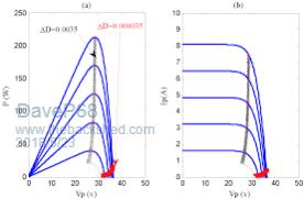 Wind MPPT is very different, in that any increase in working voltage from the PMA (F&P stator) MUST be in proportion to the shaft RPM. The current must rise at a rate 2x the increase of RPM which will be in proportion to Shaft Torque. A Wind MPPT controller usually only takes the rise/fall in voltage from the PMA as it's main input and adjusts the current in order to achieve "Maximum Power Point Tracking". The measurement of RPM can make this process easier as a 2nd reference input. Add resonance capacitors into the equation and this changes everything that I've stated above, but the increase output power that they provide can't be over looked. There are realities if you do not accept, will lead to frustration because you will be spending time on wrong assumptions and the results cannot follow! The Dunning Kruger Effect :) |
||||
