
|
|
Forum Index : Windmills : My unorthodox Build
| Author | Message | ||||
| BarkyJ Senior Member Joined: 26/04/2018 Location: New ZealandPosts: 114 |
Well, the equation at the moment doesn't use TSR directly as such, but I guess the whole equation is based around the configuration of the table which used the TSR to figure out RPM's and such, to then determine the loading applied. So yes the blade TSR is important to get within the ballpark of the intended TSR, else the table either needs to be rehashed to allow for more RPM or more torque etc, and potentially a different point to handle moving it out of the wind when the weather gets wild. When I get these blades cut, hopefully in the next week, and then the rest of the windmill built, and get a more robust controller assembled, then I guess bolt it all together and do some tests and figure out where we are at, and then adjust the controller to match the blades. Lots of trial and error to come. and work is incredibly busy at the moment... sigh. |
||||
| Warpspeed Guru Joined: 09/08/2007 Location: AustraliaPosts: 4406 |
It may be a case of approaching the whole problem from the opposite direction. Get it up and running and take some power measurements at various fairly constant wind speeds, tweaking the loading for optimum power at each wind speed increment. From that, you can build up a rough curve, then from the curve derive a suitable polynomial to fit. Once you have the polynomial expression, just apply that to the wind speed to get a continuous smooth adjustment of loading over the whole entire range. Cheers, �Tony. |
||||
DaveP68 Senior Member Joined: 25/11/2014 Location: New ZealandPosts: 292 |
The TSR isn't the main issue here as such, it's what the Dual F&P stators operating characteristics are that's important when in high wind conditions come along. The one thing we need to be mindful of is the stators have an up torque limit once reached plateau's out and if saturation is approached drops off again. My concern is if the blades perform well and end up with a TSR of say 5-6 with say just above 30 % efficiency then there will be too much torque on the shaft for the Dual stators to take. Blade runaway will occur... The solution then will not try to get as much peak power and angle the blades out of the wind when a certain pre-calculated torque level is reached. The higher TSR of around 7.5 that I recommend is just a nice to have rather than an end goal. Also there are other solutions to managing higher torque levels that are easy to implement with a simple modification to the F&P stators. There are realities if you do not accept, will lead to frustration because you will be spending time on wrong assumptions and the results cannot follow! The Dunning Kruger Effect :) |
||||
| BarkyJ Senior Member Joined: 26/04/2018 Location: New ZealandPosts: 114 |
Yep thats right. Now to get some blades made. |
||||
| BarkyJ Senior Member Joined: 26/04/2018 Location: New ZealandPosts: 114 |
I have been playing around with blades and finally took the plunge to get some cut out roughly. So the dimensions I went for to start with are 140 at the tip and 200 at the root, then tapering back to the mounting point with a bit of a lug sticking out. So larger than I was originally going to do, but it gives me material to remove, rather than wishing I had more material there later on.     Here are 2 of them roughly dressed 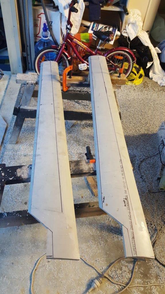 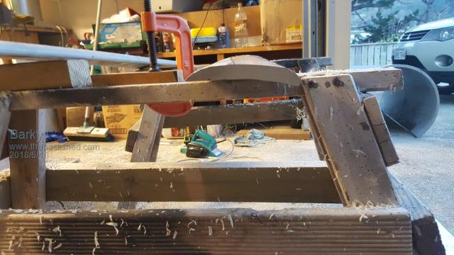 And a big pile of shavings.  Used a jig saw with a suitable PVC blade, and it cut really nicely. Then used an electric power plane to smooth the edges and then start the contouring. Cuts really well with that too. The part I am stuck on is the 'correct' way to mount these, in terms of trailing edge or leading edge, and how that is actually achieved. All PVC pipe blades I have seen to date, have been mounted on their trailing edge, with the leading edge curling forwards from the mounting plate. This is backwards compared to how 'normal' blades are mounted it seems, they all tend to get mounted with the leading edge and the trailing edge is going behind, but I just don't know if this is achievable with PVC pipe blades. More thinking and trial and error to come. |
||||
| Warpspeed Guru Joined: 09/08/2007 Location: AustraliaPosts: 4406 |
I have been thinking about this over the last few days, even having dreams about it. The way the blades have been cut they are essentially straight along their length, without having any twist between the root and the tip. The pitch of the blade remains the same over the whole length. Now what we want is laminar airflow over both sides of the blade with a fairly small angle of attack, which gives us the optimum lift drag ratio right along the whole width of the blade. Drag is important, because it acts as a brake on our rotor slowing it down and consuming power we would otherwise be able to use as useful torque. So down near the hub, the blade is hardly moving at all, and the air is rushing past parallel with the drive shaft. The leading edge should be facing almost straight ahead into the oncoming air, and the blade curl away from that slightly to give us our differential front to back pressure to create thrust without hopefully having any flow separation on either side of the blade. From that, we could probably bolt the trailing edge onto the face of a flat hub if it curled around far enough right at the hub.  At some distance along the blade, the blade velocity will be the same as the air velocity, and for the blade to still have optimum lift drag ratio the angle of attack should still be quite small, and the leading edge should be at very close to 45 degrees so that the leading edge again points directly into the effective relative airflow direction over the blade.  Right at the tip, the blade velocity is very high, perhaps ten times the wind velocity. So the relative airflow hitting the leading edge will be almost at right angles to the drive shaft, and the leading edge will appear almost at that same angle.  When we cut our blades out of a round pipe we can curl the blade around the pipe along the length so that the angle of attack varies almost over ninety degrees from tip to root. That change in pitch is an entirely different thing to the slight curvature across the blade at any point between leading and trailing edge. That is as I remember my lessons at flying school almost fifty years ago.  Cheers, �Tony. |
||||
Madness Guru Joined: 08/10/2011 Location: AustraliaPosts: 2498 |
By making the blade wider at the root and keeping the leading edge in line with the centre of the original pipe it is creating a twist. Having said that though the people using extruded aluminium blades have the angle along the entire blade. There are only 10 types of people in the world: those who understand binary, and those who don't. |
||||
| BarkyJ Senior Member Joined: 26/04/2018 Location: New ZealandPosts: 114 |
Hi Tony Yeah by placing the template on the pipe on an angle, rather than straight up and down the length, you do get this twist. I had not seen this documented as such in other builds, so I was very conservative with the blades I have cut. Mine are about 3 degrees from straight, which is hardly anything. I could do it more aggressively, but I just wasn't sure if it was the right thing to do or not. What is strange though is when you look at the GOE222 blades, they are relatively flat with their mounting, and they are a constant profile. So how do they work so well? Unsure if you have spotted the new thread I posted the other day https://www.thebackshed.com/forum/forum_posts.asp?TID=10566&PN=1&TPN=1 I guess all I can do is try and see what happens really. All calculators I have found suggest different to what I have seen people doing in practice, and the shape of the pipe blades these calculators output, involves a massive bulb at the root. Then when you look at diagrams such as this, which is more like what you just posted, it's different again to what people seem to do with pipe blades:  Confusing :) |
||||
| BarkyJ Senior Member Joined: 26/04/2018 Location: New ZealandPosts: 114 |
Hi Madness Yeah that is essentially what I ended up doing too. The leading edge is in line with the axis of the pipe, the trailing edge is at a slight angle, it worked out to be something like 3-4 degrees only. So when you mount it on the trailing edge, you get this effect of a twist, without having so much curl that the blade isn't ploughing the air. With the aluminium extruded blades, yeah, quite different concept again, constant profile over the whole length. Certainly a technical and confusing subject to get your head around. In my pics above, you might see one of the blades with the pipe printing on it, PCV blah blah. That in theory is down the length of the blade. You might be able to make out the slight angle between that line under the words, and the leading edge. |
||||
| Warpspeed Guru Joined: 09/08/2007 Location: AustraliaPosts: 4406 |
There is probably some happy medium between what is theoretically ideal, and what is practical and easy to fabricate. There might also be some mechanical tradeoffs such as weight, strength, and stiffness which may vary with the material used. If you were manufacturing blades professionally, aesthetics and cost are other factors. Noise could come into all this as well, but a well designed blade should not have any flow separation or generate any tip vortices, and should run pretty silent. I live in the suburbs surrounded by two story houses and large trees, and a not very understanding local council. My interest in all of this is only mainly from curiosity and perhaps learning something new and interesting. If I was doing it myself, I would probably build and test some scale models, particularly easy to do with PVC pipe of widely varying sizes. Cheers, �Tony. |
||||
| Madness Guru Joined: 08/10/2011 Location: AustraliaPosts: 2498 |
If you search you will find blade calculators that give the cross-section of the blade at intervals. I went through all this a few years ago and made a fibreglass mould off of a wooden template. Never got around to finishing it though, maybe one day I will get back to it. It was a huge amount of work though, what you are doing would take a fraction of the time. There are only 10 types of people in the world: those who understand binary, and those who don't. |
||||
| Warpspeed Guru Joined: 09/08/2007 Location: AustraliaPosts: 4406 |
It might also be possible to make a wooden master, and form some PVC (pipe) blades using heat to conform to the wooden master. If done slowly in a large oven, it may make some pretty radical shapes possible and repeatable. Cheers, �Tony. |
||||
| BarkyJ Senior Member Joined: 26/04/2018 Location: New ZealandPosts: 114 |
Yep I have found a number of calculators, and all of them made very large root, like 400mm+, absolute monsters. They were huge, I printed one out to scale and put it on the pipe, but it just seemed rediculous. |
||||
| Warpspeed Guru Joined: 09/08/2007 Location: AustraliaPosts: 4406 |
Without ever trying one of those calculators myself, I can well believe that the mathematical extremes reached can be pretty radical when converted into actual hardware. My gut feeling tells me there is not a lot to be gained right down near the hub anyway, there is just no leverage down there, so you could probably trim back the trailing edge a whole lot without losing very much. As far as flow separation and turbulence go, its the angle of the leading edge that I believe is absolutely critical, and where you need to have the twist. If the flow is going to become unstuck and turbulent, you want that to occur as far back near the trailing edge as possible. So I would try very hard to get the leading edge correct with some twist, and slim down the trailing edge if it gets really crazy huge down near the hub. If you can make a long skinny oven out of some insulated airconditioning duct and a heat gun, or something along those lines, with extra heat and extra insulation, if you clamped your blades between two wooden masters and let it heat soak for a few hours that should work. My own experience with PVC pressure pipe used in commercial swimming pool heating is that it starts to sag at about 80 Celsius. If due to some system control fault it ever gets that hot, the PVC deforms permanently. I have seen this sagging pipe effect both with solar and gas boiler heating, that went horribly wrong. Cheers, �Tony. |
||||
| Boppa Guru Joined: 08/11/2016 Location: AustraliaPosts: 814 |
I noticed that some of the big wind gennies use winglets at the tip of the blade, similar to what planes use on the ends of their wings, apparently it increases lift and reduces noise |
||||
| Warpspeed Guru Joined: 09/08/2007 Location: AustraliaPosts: 4406 |
Yes vortex formation at the tip is a real noise maker. The air flows around the outside edge from the high pressure side to the low pressure side which starts a vortex forming right at the tip. Its why the tips of wings and propellers are usually rounded. Another solution is with a little fence along the tip of a square ended wing or blade. This was also the basis of Alan Bond's famous "winged keel" when he was Americas Cup yacht racing. It cuts down drag and in the case of a wind turbine noise. Slim blades with a rounded tip also work well and look a lot neater, but if you are trying to get max efficiency with minimum length, a flat ended blade with a fence is the only real option. Cheers, �Tony. |
||||
| BarkyJ Senior Member Joined: 26/04/2018 Location: New ZealandPosts: 114 |
Certainly is interesting stuff What do you guys make of this one? Just the concept, more than the actual thing. https://www.youtube.com/watch?v=4Pa3-pVYSLQ He has it so the straight side is the leading edge, and the side with the fat heal is the trailing edge. Which is opposite to other pipe blade setups you typically see... |
||||
| Madness Guru Joined: 08/10/2011 Location: AustraliaPosts: 2498 |
If you look at the little FPV racing Drones the props on them have the tip angled back at about 45 degrees to reduce noise and improve efficiency. They do massive RPMs, saw a little one yesterday with 3" props and the thing can do in excess of 160KMH. There are only 10 types of people in the world: those who understand binary, and those who don't. |
||||
| BarkyJ Senior Member Joined: 26/04/2018 Location: New ZealandPosts: 114 |
Check these Winglets out https://www.youtube.com/watch?v=HP3aAa_w2S4 |
||||
| Madness Guru Joined: 08/10/2011 Location: AustraliaPosts: 2498 |
That is very similar to the little drone props. There are only 10 types of people in the world: those who understand binary, and those who don't. |
||||
