
|
|
Forum Index : Microcontroller and PC projects : Armmite - STM32H7: Developments
| Author | Message | ||||
goc30 Guru Joined: 12/04/2017 Location: FrancePosts: 425 |
I confirm if you use STM32CubeProg, with version 5.04.28, MMedit can't load progs (it can't erase memory) With new stlink it work correctly (need to download stlink004/stlink007/stlink009) peter: I abandon the idea to use serial port and i2c (with pic32mx170 as slave) on rpi, it does not work properly (I lose gps frames and some times rpi corrupt i2c), so I go back to the stm32h7 where i don't need to use a slave |
||||
TassyJim Guru Joined: 07/08/2011 Location: AustraliaPosts: 5895 |
I just tried using STM32CubeProgrammer to install the version 5.04.28 and had no problems loading a test program by 'load and run' or by 'new' and 'load' in MMChat. Erasing the memory takes a long time. I always do a full erase before load the new firmware. I will install ST-LINK 'to be sure' Jim VK7JH MMedit MMBasic Help |
||||
| matherp Guru Joined: 11/12/2012 Location: United KingdomPosts: 8572 |
Bug fix to correct USB keyboard 2018-08-18_174133_Armmite1.3.zip I had all sorts of strange symptoms that you may or may not notice. In my case MMBasic ran fine and would do exactly what you have described but if I typed "OPTION SDCARD 110" I got the message "Command not found"!!!! It appeared as if bits of the code weren't getting programmed but most of it was OK |
||||
| goc30 Guru Joined: 12/04/2017 Location: FrancePosts: 425 |
i have problems with sd card versus 4bits it is certainly my fault, but after read all infos about sd card on armite, i am in "trouble" I have the 2 types of sd card, 4bits and spi and 4bit_sdcard don't work, i have the same msg "sd card not present" when i send "files" from stlink connection the spi model is the Adafruit model i had connected this card in pf8(DO)-pf7(clk)-pf9(DI)-pd0(cs)-pd1(cd) and it work correctly (option sdcard 115,114) the 4 bit model is the SparkFun model i have connecte pins as you give (98,99,111,112,113,116,87) and put "option sdcard 112,87". I have a dyi card is-it necessary to connect also pins 98,116,113 to 20,21,19 ?? in this topic, you wrote that it necessary to put pullup (10k) on pins, is it wright?? thanks goc |
||||
| matherp Guru Joined: 11/12/2012 Location: United KingdomPosts: 8572 |
4-bit is no longer supported. The STM supplied drivers were both unreliable and slow |
||||
| goc30 Guru Joined: 12/04/2017 Location: FrancePosts: 425 |
thank peter  it's beter for me |
||||
| gadgetjack Senior Member Joined: 15/07/2016 Location: United StatesPosts: 127 |
Peter , I know this is a long shot , but would your code be able to run on a 32f767 nucleo board also? I have an extra (ordered by mistake) and would like to get some use from it. Not a big deal , just thought I would ask. My other board is running like a clock. all functions running perfect thanks to you. I tip my hat.... |
||||
| JohnS Guru Joined: 18/11/2011 Location: United KingdomPosts: 3650 |
If every I/O device functions exactly the same, is at the same address, and all the interrupts are identical, plus all the pins are the same, then it's probably not a huge amount of work so long as the ROM & RAM are at the same addresses and everything can be configured using the same code as the H7. Otherwise I expect it'll be hours of slogging and endless referring to the datasheets. DIY? John |
||||
| lizby Guru Joined: 17/05/2016 Location: United StatesPosts: 3011 |
One of my first questions for the same reason. Not impossible, but not practical, Peter said. PicoMite, Armmite F4, SensorKits, MMBasic Hardware, Games, etc. on fruitoftheshed |
||||
| matherp Guru Joined: 11/12/2012 Location: United KingdomPosts: 8572 |
Yes it can be done but there is relatively little advantage over the MMX and it would just be another port to maintain. Lots of things are different about the H7 vs F7 in particular the clocks and the memory map. These would need quite a lot of work. To give you an insight into the H7 setup, the attached is the configuration screen for the clocks in the chip (lots of them!!) 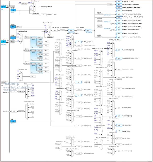 |
||||
| gadgetjack Senior Member Joined: 15/07/2016 Location: United StatesPosts: 127 |
A fair answer. I will set it aside for a rainy day project some time. |
||||
| goc30 Guru Joined: 12/04/2017 Location: FrancePosts: 425 |
Hi peter a question please TOUCH function work correctly, but in Micromite versus, I can use interrupt mode in H7 versus, basic said that pin t_irq is not aviable (use by option touch) ex: option touch 56,123 setpin 123,intl,myirq in my case, i replace this code by do If Touch(down)<>0 Then if flgtouch=0 or flgtouch=2 then toposx=touch(x) toposy=touch(y) 'Print toposx,toposy flgtouch=1 sptouchd 'routine for manage down touch else 'for last point use before UP if touch(x)=>0 then toposx1=touch(x) toposy1=touch(y) end if end if End If if touch(up)<>0 then if flgtouch=1 then flgtouch=2 'print toposx1,toposy1 sptouchu 'routine for manage up touch end if end if loop it is just question to have compatibility with Micromite |
||||
| matherp Guru Joined: 11/12/2012 Location: United KingdomPosts: 8572 |
It is only the MM2 that allows this, the MM+ is the same as the H7 because these support the command GUI INTERRUPT. See around page 18 of the MM+ manual for details #if defined(MX170) // this allows the MX170 version to set a software interrupt on the touch IRQ pin if(pin == Option.TOUCH_IRQ) { if(value == EXT_INT_HI || value == EXT_INT_LO || value == EXT_INT_BOTH) ExtCurrentConfig[pin] = value; else if(value == EXT_NOT_CONFIG) { ExtCurrentConfig[pin] = EXT_BOOT_RESERVED; for(i = 0; i < NBRINTERRUPTS; i++) if(inttbl.pin == pin) inttbl.pin = 0; // disable the software interrupt on this pin } else error("Pin % is reserved on startup", pin); } else #endif |
||||
| goc30 Guru Joined: 12/04/2017 Location: FrancePosts: 425 |
Hi peter I tested your solution, it's good except that the function "UP" does not return the coordinates. it send -1,-1 and the "Touch(LastX) also my code GUI INTERRUPT sptouchd,sptouchu 'gestion ecran tactile ... '***************************** sub sptouchd 'gestion appuye ecran touce if flgtouch=0 or flgtouch=2 then toposx=touch(x) toposy=touch(y) flgtouch=1 end if print "ecran touche en :"; print toposx,toposy end sub sub sptouchu 'gestion relachement ecran touche if flgtouch=1 then flgtouch=2 toposx1=touch(x) toposy1=touch(y) end if print "ecran relache en :"; print toposx1,toposy1,touch(LastX),TOUCH(lasty) end sub |
||||
| matherp Guru Joined: 11/12/2012 Location: United KingdomPosts: 8572 |
From the MM+ manual This appears to be a bug in the MM+ code. I've reported it to Geoff. I've attached a fix for the transparent text outside the screen bug UPDATE may also have fixed the Touch(lastX) bug 2018-08-27_023202_Armmite1.3.zip |
||||
| panky Guru Joined: 02/10/2012 Location: AustraliaPosts: 1094 |
Hi Peter, I received my Backpack from China today using your Gerbers and would like to start testing. Do you have a circuit diagram for the Backpack that you are willing to share? I have an ILI9481 4" display connected to the Nucleo and it works fine - looks good! Regards, Doug. ... almost all of the Maximites, the MicromMites, the MM Extremes, the ArmMites, the PicoMite and loving it! |
||||
| matherp Guru Joined: 11/12/2012 Location: United KingdomPosts: 8572 |
Nothing other than the partial diagram in this thread . The rest is just connections to the various headers as per the pin allocation and the labelling on the PCB. I just wired the layout on the PCB rather than from a full schematic. { NULL, 0, PUNUSED , NULL, 0}, // pin 0 { GPIOE, GPIO_PIN_2, DIGITAL_IN | DIGITAL_OUT , NULL, 0}, // pin 1 SSD_D2 { GPIOE, GPIO_PIN_3, DIGITAL_IN | DIGITAL_OUT , NULL, 0}, // pin 2 SSD_D3 { GPIOE, GPIO_PIN_4, DIGITAL_IN | DIGITAL_OUT , NULL, 0}, // pin 3 SSD_D4 { GPIOE, GPIO_PIN_5, DIGITAL_IN | DIGITAL_OUT , NULL, 0}, // pin 4 SSD_D5 { GPIOE, GPIO_PIN_6, DIGITAL_IN | DIGITAL_OUT , NULL, 0}, // pin 5 SSD_D6 { NULL, 0, PUNUSED , NULL, 0}, // pin 6 VBAT { GPIOC, GPIO_PIN_13, DIGITAL_IN | DIGITAL_OUT , NULL, 0}, // pin 7 - Push Button { NULL, 0, PUNUSED , NULL, 0}, // pin 8 OSC32-IN { NULL, 0, PUNUSED , NULL, 0}, // pin 9 OSC32-OUT { GPIOF, GPIO_PIN_0, DIGITAL_IN | DIGITAL_OUT , NULL, 0}, // pin 10 COUNT1 { GPIOF, GPIO_PIN_1, DIGITAL_IN | DIGITAL_OUT , NULL, 0}, // pin 11 COUNT2 { GPIOF, GPIO_PIN_2, DIGITAL_IN | DIGITAL_OUT , NULL, 0}, // pin 12 COUNT3 { GPIOF, GPIO_PIN_3, DIGITAL_IN | DIGITAL_OUT | ANALOG_IN , ADC3, ADC_CHANNEL_5}, // pin 13 COUNT4 { GPIOF, GPIO_PIN_4, DIGITAL_IN | DIGITAL_OUT | ANALOG_IN , ADC3, ADC_CHANNEL_9}, // pin 14 IR { GPIOF, GPIO_PIN_5, DIGITAL_IN | DIGITAL_OUT | ANALOG_IN , ADC3, ADC_CHANNEL_4}, // pin 15 { NULL, 0, PUNUSED , NULL, 0}, // pin 16 VSS { NULL, 0, PUNUSED , NULL, 0}, // pin 17 VDD { GPIOF, GPIO_PIN_6, DIGITAL_IN | DIGITAL_OUT | ANALOG_IN , ADC3, ADC_CHANNEL_8}, // pin 18 { GPIOF, GPIO_PIN_7, DIGITAL_IN | DIGITAL_OUT | ANALOG_IN , ADC3, ADC_CHANNEL_3}, // pin 19 SPI5-CLK { GPIOF, GPIO_PIN_8, DIGITAL_IN | DIGITAL_OUT | ANALOG_IN , ADC3, ADC_CHANNEL_7}, // pin 20 SPI5-IN { GPIOF, GPIO_PIN_9, DIGITAL_IN | DIGITAL_OUT | ANALOG_IN , ADC3, ADC_CHANNEL_2}, // pin 21 SPI5-OUT { GPIOF, GPIO_PIN_10, DIGITAL_IN | DIGITAL_OUT | ANALOG_IN , ADC3, ADC_CHANNEL_6}, // pin 22 { NULL, 0, PUNUSED , NULL, 0}, // pin 23 RCC-OSCIN { NULL, 0, PUNUSED , NULL, 0}, // pin 24 RCC-OSCOUT { NULL, 0, PUNUSED , NULL, 0}, // pin 25 NRST { GPIOC, GPIO_PIN_0, DIGITAL_IN | DIGITAL_OUT | ANALOG_IN , ADC3, ADC_CHANNEL_10}, // pin 26 OV7670_DAT0 { GPIOC, GPIO_PIN_1, DIGITAL_IN | DIGITAL_OUT | ANALOG_IN , ADC3, ADC_CHANNEL_11}, // pin 27 SPI2-OUT, OV7670_DAT1 { GPIOC, GPIO_PIN_2, DIGITAL_IN | DIGITAL_OUT | ANALOG_IN , ADC3, ADC_CHANNEL_0}, // pin 28 SPI2-IN, OV7670_DAT2 { GPIOC, GPIO_PIN_3, DIGITAL_IN | DIGITAL_OUT | ANALOG_IN , ADC3, ADC_CHANNEL_1}, // pin 29 OV7670_DAT3 { NULL, 0, PUNUSED , NULL, 0}, // pin 30 VDD { NULL, 0, PUNUSED , NULL, 0}, // pin 31 VSSA { NULL, 0, PUNUSED , NULL, 0}, // pin 32 VREF+ { NULL, 0, PUNUSED , NULL, 0}, // pin 33 VDDA { GPIOA, GPIO_PIN_0, DIGITAL_IN | DIGITAL_OUT | ANALOG_IN , ADC1, ADC_CHANNEL_16}, // pin 34 PWM-2A { GPIOA, GPIO_PIN_1, DIGITAL_IN | DIGITAL_OUT | ANALOG_IN , ADC1, ADC_CHANNEL_17}, // pin 35 PWM-2B { GPIOA, GPIO_PIN_2, DIGITAL_IN | DIGITAL_OUT | ANALOG_IN , ADC1, ADC_CHANNEL_14}, // pin 36 PWM-2C // { GPIOA, GPIO_PIN_3, DIGITAL_IN | DIGITAL_OUT | ANALOG_IN , ADC1, ADC_CHANNEL_15}, // pin 37 PWM-2D { NULL, 0, PUNUSED , NULL, 0}, // pin 38 VSS { NULL, 0, PUNUSED , NULL, 0}, // pin 39 VDD { NULL, 0, PUNUSED , NULL, 0}, // pin 40 DAC1 { NULL, 0, PUNUSED , NULL, 0}, // pin 41 DAC2 { GPIOA, GPIO_PIN_6, DIGITAL_IN | DIGITAL_OUT | ANALOG_IN , ADC1, ADC_CHANNEL_3}, // pin 42 SPI-IN { GPIOA, GPIO_PIN_7, DIGITAL_IN | DIGITAL_OUT | ANALOG_IN , ADC1, ADC_CHANNEL_7}, // pin 43 SPI-OUT { GPIOC, GPIO_PIN_4, DIGITAL_IN | DIGITAL_OUT | ANALOG_IN , ADC1, ADC_CHANNEL_4}, // pin 44 OV7670_DAT4 { GPIOC, GPIO_PIN_5, DIGITAL_IN | DIGITAL_OUT | ANALOG_IN , ADC1, ADC_CHANNEL_8}, // pin 45 OV7670_DAT5 { GPIOB, GPIO_PIN_0, DIGITAL_IN | DIGITAL_OUT | ANALOG_IN , ADC1, ADC_CHANNEL_9}, // pin 46 Green-LED { GPIOB, GPIO_PIN_1, DIGITAL_IN | DIGITAL_OUT | ANALOG_IN , ADC1, ADC_CHANNEL_5}, // pin 47 { GPIOB, GPIO_PIN_2, DIGITAL_IN | DIGITAL_OUT , NULL, 0}, // pin 48 SPI3-OUT { GPIOF, GPIO_PIN_11, DIGITAL_IN | DIGITAL_OUT | ANALOG_IN , ADC1, ADC_CHANNEL_2}, // pin 49 { GPIOF, GPIO_PIN_12, DIGITAL_IN | DIGITAL_OUT | ANALOG_IN , ADC1, ADC_CHANNEL_6}, // pin 50 { NULL, 0, PUNUSED , NULL, 0}, // pin 51 VSS { NULL, 0, PUNUSED , NULL, 0}, // pin 52 VDD { GPIOF, GPIO_PIN_13, DIGITAL_IN | DIGITAL_OUT | ANALOG_IN ,ADC2, ADC_CHANNEL_2}, // pin 53 { GPIOF, GPIO_PIN_14, DIGITAL_IN | DIGITAL_OUT | ANALOG_IN ,ADC2, ADC_CHANNEL_6}, // pin 54 { GPIOF, GPIO_PIN_15, DIGITAL_IN | DIGITAL_OUT , NULL, 0}, // pin 55 { GPIOG, GPIO_PIN_0, DIGITAL_IN | DIGITAL_OUT , NULL, 0}, // pin 56 { GPIOG, GPIO_PIN_1, DIGITAL_IN | DIGITAL_OUT , NULL, 0}, // pin 57 SSD_RS { GPIOE, GPIO_PIN_7, DIGITAL_IN | DIGITAL_OUT , NULL, 0}, // pin 58 SSD_D7 { GPIOE, GPIO_PIN_8, DIGITAL_IN | DIGITAL_OUT , NULL, 0}, // pin 59 SSD_D8 { GPIOE, GPIO_PIN_9, DIGITAL_IN | DIGITAL_OUT , NULL, 0}, // pin 60 SSD_D9 { NULL, 0, PUNUSED , NULL, 0}, // pin 61 VSS { NULL, 0, PUNUSED , NULL, 0}, // pin 62 VDD { GPIOE, GPIO_PIN_10, DIGITAL_IN | DIGITAL_OUT , NULL, 0}, // pin 63 SSD_D10 { GPIOE, GPIO_PIN_11, DIGITAL_IN | DIGITAL_OUT , NULL, 0}, // pin 64 SSD_D11 { GPIOE, GPIO_PIN_12, DIGITAL_IN | DIGITAL_OUT , NULL, 0}, // pin 65 SSD_D12 { GPIOE, GPIO_PIN_13, DIGITAL_IN | DIGITAL_OUT , NULL, 0}, // pin 66 SSD_D13 { GPIOE, GPIO_PIN_14, DIGITAL_IN | DIGITAL_OUT , NULL, 0}, // pin 67 SSD_D14 { GPIOE, GPIO_PIN_15, DIGITAL_IN | DIGITAL_OUT , NULL, 0}, // pin 68 SSD_D15 { GPIOB, GPIO_PIN_10, DIGITAL_IN | DIGITAL_OUT , NULL, 0}, // pin 69 I2C2-SCL { GPIOB, GPIO_PIN_11, DIGITAL_IN | DIGITAL_OUT , NULL, 0}, // pin 70 I2C2-SDA { NULL, 0, PUNUSED , NULL, 0}, // pin 71 VCAP { NULL, 0, PUNUSED , NULL, 0}, // pin 72 VDD /// { GPIOB, GPIO_PIN_12, DIGITAL_IN | DIGITAL_OUT , NULL, 0}, // pin 73 COM3-RX (UART5) { GPIOB, GPIO_PIN_13, DIGITAL_IN | DIGITAL_OUT , NULL, 0}, // pin 74 COM3-TX (UART5) { GPIOB, GPIO_PIN_14, DIGITAL_IN | DIGITAL_OUT , NULL, 0}, // pin 75 Red-LED { GPIOB, GPIO_PIN_15, DIGITAL_IN | DIGITAL_OUT , NULL, 0}, // pin 76 COM1-RX { NULL, 0, PUNUSED , NULL, 0}, // pin 77 CONSOLE-TX { NULL, 0, PUNUSED , NULL, 0}, // pin 78 CONSOLE-RX { GPIOD, GPIO_PIN_10, DIGITAL_IN | DIGITAL_OUT , NULL, 0}, // pin 79 { GPIOD, GPIO_PIN_11, DIGITAL_IN | DIGITAL_OUT , NULL, 0}, // pin 80 { GPIOD, GPIO_PIN_12, DIGITAL_IN | DIGITAL_OUT , NULL, 0}, // pin 81 PWM-1A { GPIOD, GPIO_PIN_13, DIGITAL_IN | DIGITAL_OUT , NULL, 0}, // pin 82 PWM-1B { NULL, 0, PUNUSED , NULL, 0}, // pin 83 VSS { NULL, 0, PUNUSED , NULL, 0}, // pin 84 VDD { GPIOD, GPIO_PIN_14, DIGITAL_IN | DIGITAL_OUT , NULL, 0}, // pin 85 PWM-1C { GPIOD, GPIO_PIN_15, DIGITAL_IN | DIGITAL_OUT , NULL, 0}, // pin 86 PWM-1D { GPIOG, GPIO_PIN_2, DIGITAL_IN | DIGITAL_OUT , NULL, 0}, // pin 87 SD_CD { GPIOG, GPIO_PIN_3, DIGITAL_IN | DIGITAL_OUT , NULL, 0}, // pin 88 OV7670_PCLK { GPIOG, GPIO_PIN_4, DIGITAL_IN | DIGITAL_OUT , NULL, 0}, // pin 89 OV7670_VSYNC { GPIOG, GPIO_PIN_5, DIGITAL_IN | DIGITAL_OUT , NULL, 0}, // pin 90 OV7670_HREF { NULL, 0, PUNUSED , NULL, 0}, // pin 91 USB-POWER { GPIOG, GPIO_PIN_7, DIGITAL_IN | DIGITAL_OUT , NULL, 0}, // pin 92 { GPIOG, GPIO_PIN_8, DIGITAL_IN | DIGITAL_OUT , NULL, 0}, // pin 93 COUNT5-HIGHSPEED { NULL, 0, PUNUSED , NULL, 0}, // pin 94 VSS { NULL, 0, PUNUSED , NULL, 0}, // pin 95 VDDUSB { GPIOC, GPIO_PIN_6, DIGITAL_IN | DIGITAL_OUT , NULL, 0}, // pin 96 OV7670_DAT6 { GPIOC, GPIO_PIN_7, DIGITAL_IN | DIGITAL_OUT , NULL, 0}, // pin 97 OV7670_DAT7 { GPIOC, GPIO_PIN_8, DIGITAL_IN | DIGITAL_OUT , NULL, 0}, // pin 98 { GPIOC, GPIO_PIN_9, DIGITAL_IN | DIGITAL_OUT , NULL, 0}, // pin 99 { GPIOA, GPIO_PIN_8, DIGITAL_IN | DIGITAL_OUT , NULL, 0}, // pin 100 OV7670_XCLK { GPIOA, GPIO_PIN_9, DIGITAL_IN | DIGITAL_OUT , NULL, 0}, // pin 101 { GPIOA, GPIO_PIN_10, DIGITAL_IN | DIGITAL_OUT , NULL, 0}, // pin 102 { NULL, 0, PUNUSED , NULL, 0}, // pin 103 USB-D+ { NULL, 0, PUNUSED , NULL, 0}, // pin 104 USB-D- { NULL, 0, PUNUSED , NULL, 0}, // pin 105 SWDIO { NULL, 0, PUNUSED , NULL, 0}, // pin 106 VCAP { NULL, 0, PUNUSED , NULL, 0}, // pin 107 VSS { NULL, 0, PUNUSED , NULL, 0}, // pin 108 VDD // { NULL, 0, PUNUSED , NULL, 0}, // pin 109 SWCLK { GPIOA, GPIO_PIN_15, DIGITAL_IN | DIGITAL_OUT , NULL, 0}, // pin 110 { GPIOC, GPIO_PIN_10, DIGITAL_IN | DIGITAL_OUT , NULL, 0}, // pin 111 { GPIOC, GPIO_PIN_11, DIGITAL_IN | DIGITAL_OUT , NULL, 0}, // pin 112 { GPIOC, GPIO_PIN_12, DIGITAL_IN | DIGITAL_OUT , NULL, 0}, // pin 113 { GPIOD, GPIO_PIN_0, DIGITAL_IN | DIGITAL_OUT , NULL, 0}, // pin 114 { GPIOD, GPIO_PIN_1, DIGITAL_IN | DIGITAL_OUT , NULL, 0}, // pin 115 { GPIOD, GPIO_PIN_2, DIGITAL_IN | DIGITAL_OUT , NULL, 0}, // pin 116 { GPIOD, GPIO_PIN_3, DIGITAL_IN | DIGITAL_OUT , NULL, 0}, // pin 117 SPI2-CLK { GPIOD, GPIO_PIN_4, DIGITAL_IN | DIGITAL_OUT , NULL, 0}, // pin 118 COM2-DE { GPIOD, GPIO_PIN_5, DIGITAL_IN | DIGITAL_OUT , NULL, 0}, // pin 119 COM2-TX { NULL, 0, PUNUSED , NULL, 0}, // pin 120 VSS { NULL, 0, PUNUSED , NULL, 0}, // pin 121 VDD { GPIOD, GPIO_PIN_6, DIGITAL_IN | DIGITAL_OUT , NULL, 0}, // pin 122 COM2-RX { GPIOD, GPIO_PIN_7, DIGITAL_IN | DIGITAL_OUT , NULL, 0}, // pin 123 { GPIOG, GPIO_PIN_9, DIGITAL_IN | DIGITAL_OUT , NULL, 0}, // pin 124 COM4-RX (USART6) { GPIOG, GPIO_PIN_10, DIGITAL_IN | DIGITAL_OUT , NULL, 0}, // pin 125 SSD_WR { GPIOG, GPIO_PIN_11, DIGITAL_IN | DIGITAL_OUT , NULL, 0}, // pin 126 SPI-CLK { GPIOG, GPIO_PIN_12, DIGITAL_IN | DIGITAL_OUT , NULL, 0}, // pin 127 SSD_RESET { GPIOG, GPIO_PIN_13, DIGITAL_IN | DIGITAL_OUT , NULL, 0}, // pin 128 SSD_RD { GPIOG, GPIO_PIN_14, DIGITAL_IN | DIGITAL_OUT , NULL, 0}, // pin 129 COM4-TX (USART6) { NULL, 0, PUNUSED , NULL, 0}, // pin 130 VSS { NULL, 0, PUNUSED , NULL, 0}, // pin 131 VDD { GPIOG, GPIO_PIN_15, DIGITAL_IN | DIGITAL_OUT , NULL, 0}, // pin 132 { GPIOB, GPIO_PIN_3, DIGITAL_IN | DIGITAL_OUT , NULL, 0}, // pin 133 SPI3-CLK { GPIOB, GPIO_PIN_4, DIGITAL_IN | DIGITAL_OUT , NULL, 0}, // pin 134 SPI3-IN { GPIOB, GPIO_PIN_5, DIGITAL_IN | DIGITAL_OUT , NULL, 0}, // pin 135 { GPIOB, GPIO_PIN_6, DIGITAL_IN | DIGITAL_OUT , NULL, 0}, // pin 136 COM1-TX { GPIOB, GPIO_PIN_7, DIGITAL_IN | DIGITAL_OUT , NULL, 0}, // pin 137 Blue-LED { NULL, 0, PUNUSED , NULL, 0}, // pin 138 BOOT0 { NULL, 0, PUNUSED , NULL, 0}, // pin 139 I2C-SCL { NULL, 0, PUNUSED , NULL, 0}, // pin 140 I2C-SDA { GPIOE, GPIO_PIN_0, DIGITAL_IN | DIGITAL_OUT , NULL, 0}, // pin 141 SSD_D0 { GPIOE, GPIO_PIN_1, DIGITAL_IN | DIGITAL_OUT , NULL, 0}, // pin 142 SSD_D1 { NULL, 0, PUNUSED , NULL, 0}, // pin 143 PDR-ON { NULL, 0, PUNUSED , NULL, 0}, // pin 144 VDD |
||||
| panky Guru Joined: 02/10/2012 Location: AustraliaPosts: 1094 |
Thanks Peter, looking forward to exploring the ArmMite😀😀 Doug. ... almost all of the Maximites, the MicromMites, the MM Extremes, the ArmMites, the PicoMite and loving it! |
||||
| matherp Guru Joined: 11/12/2012 Location: United KingdomPosts: 8572 |
This update (no version change) fixes a couple of bugs in GPS handling. 2018-08-29_211035_Armmite1.3.zip In addition I've included a diagnostic for GPS. Use OPEN "COMn:baudrate" as GPS [, timeoffset] [,monitor] e.g. OPEN "com4:9600" as GPS, 2, 1 'switches on GPS monitoring Monitoring will output to the console the GPS messages as they are received. The critical message is GPRMC. The code looks for the parameter after the time to be an "A" to indicate data is valid. If the parameter is a "V" this indicates the data is invalid. This drives the GPS(VALID) function and no other GPS functions should be used unless GPS(VALID) is non-zero. Monitoring can be turned off with: CLOSE GPS Re-opening with the monitoring parameter set to 0 or missing will run normally. |
||||
| goc30 Guru Joined: 12/04/2017 Location: FrancePosts: 425 |
hi peter test update ok, no pb, gps work correctly it is a good idea to put monitoring function re-opening Com is also good tomorrow I will test function "send frame to gps" but it is more complexe because not all gps card have this possibility 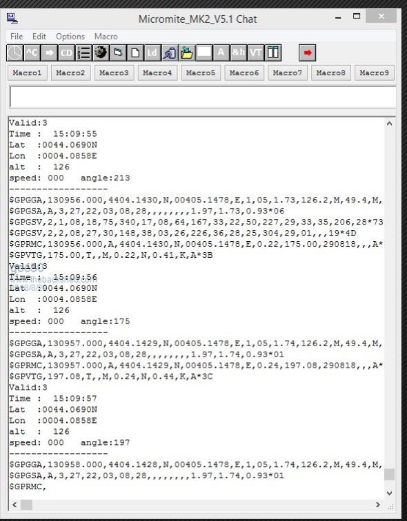 |
||||
