
|
|
Forum Index : Microcontroller and PC projects : Armmite - STM32H7: Developments
| Author | Message | ||||
TassyJim Guru Joined: 07/08/2011 Location: AustraliaPosts: 5879 |
Peter, The clock seems to loose 2 or 3 seconds every time I do a 'NEW' The RTC seems to be OK so a restart or reset bring the time back to correct. System clock not advancing when busy doing NEW? Jim VK7JH MMedit MMBasic Help |
||||
| matherp Guru Joined: 11/12/2012 Location: United KingdomPosts: 8566 |
Yes, interrupts have to be disabled when writing to flash. I'll put a call the read the RTC into the "NEW" command in the next release Bug There is a bug when you try and edit a program with a DEFINE FONT using the in-built editor. When you save the program the Armmite will lock up and need to be re-flashed. There is some difficult code in this area as the STM32H7 only lets you write to flash in 32-byte blocks which is different from the PIC and I clearly haven't got it fully sorted yet. |
||||
| geeken Newbie Joined: 13/01/2018 Location: United StatesPosts: 20 |
Peter Excellent project - appreciate you advancing it so fast ! With regard the display work done so far are you using either of the ; - LCD-TFT controller - Chrom-ART Accelerator (DMA2D) modules in the H7 ? On another note, it could be well worth getting VGA going as found on the Micromite MMX-144's / Maximites. Most folks have an old VGA screen lying around and they are way bigger than 5 or 8" - - - Maybe the above video-related modules could be used for that purpose, if that helps - it seems these items run independently of the CPU. Thanks geeken USA * * |
||||
| JohnS Guru Joined: 18/11/2011 Location: United KingdomPosts: 3649 |
It may well have the same CPU basics but quite different I/O etc, thus needing a lot of effort to create something at about the same cost but much reduced features, and using up scarce time to do the re-write. Have a go yourself, to save Peter's time? Alternatively, stick to an STM32 cpu and the job should be rather simpler as ST stick to roughly the same I/O etc. John |
||||
| isochronic Guru Joined: 21/01/2012 Location: AustraliaPosts: 689 |
my mistake - saw the M4 of both and overlooked the differences. |
||||
| matherp Guru Joined: 11/12/2012 Location: United KingdomPosts: 8566 |
Attached 5.04.18 2018-06-26_012447_Armmite.zip This fixes the issue with loadable fonts/Cfunctions (what a pig that was to diagnose!!!) and the time loss during NEW commands. Also, you can now reset memory and options by holding down the USER button on the Nucleo while pressing the RESET button - same as using "!!!!!!" on the MM and MM+. I've also been able to prove CFunctions work using an old one from the very original F4 Armmite. This was compiled on Coocox COIDE for the STM32F4 but works perfectly on the H7  CFUNCTION strrev 00000000 b085b480 6078af00 687b6039 60bb781b b2da68bb 701a683b 60fb2301 683ae00d 441368fb 68fa68b9 32011a8a 440a6879 701a7812 330168fb 68bb60fb 68fb1c5a d8ec429a 461a68bb 0300f04f 46194610 46bd3714 7b04f85d bf004770 END CFUNCTION 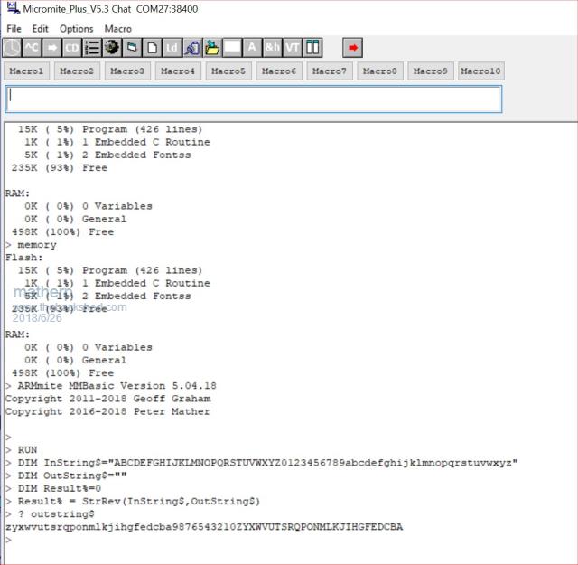 |
||||
| geeken Newbie Joined: 13/01/2018 Location: United StatesPosts: 20 |
Has anyone had experience with the ST 'C' compiler ; https://atollic.com/truestudio/ ?? ST made a very skilled decision to acquire this compiler from Atollic & make it free. I can tell its well created because it fired up in my Devuan based PC, without a hitch. Also, it's been around for a long time so I am assuming that its perfected for the STM L4 / F4 / H7, etc controllers. Feedback appreciated ! Thanks GeeKen |
||||
| matherp Guru Joined: 11/12/2012 Location: United KingdomPosts: 8566 |
Yes - hated it it  First, it is the same compiler and linker as everything else - The GCC compiler and linker Second, it is the same IDE as everything else - Eclipse The differences then are how it integrates them into a tool chain and I found it clunky and difficult compared to the (also free) "System Workbench for STM32" Installing it "bu...ed" up the SW install as it uses all the same extensions and if you import a project into it it "bu..ers" up the project for everything else. I never got the debugger to work properly over St-link. It doesn't create normal "release" and "debug" versions when you create a new project and the toolbar usage is bizarre compared to other eclipse implementations. |
||||
| geeken Newbie Joined: 13/01/2018 Location: United StatesPosts: 20 |
* Peter Goes to show - looks can potentially be very deceiving ! Thanks for giving it to us straight - appreciate your feedback. GeeKen |
||||
| matherp Guru Joined: 11/12/2012 Location: United KingdomPosts: 8566 |
Please find attached 5.4.19 2018-06-30_021248_Armmite.zip This implements analogue to digital conversion (this just leaves PWM of the basic MM capabilities) Valid analogue pins are: 13, 14, 15, 18, 19, 20, 21, 22, 26, 27, 28, 29, 34, 35, 36, 37, 42, 43, 44, 45, 46, 47, 49, 50, 53, 54 usage is as per the MM and as with the MM the voltages assume the chip is fed with 3.3V SETPIN n,AIN ? pin(n) In addition there are 6 "pseudo" pins (no SETPIN required) DAC1, DAC2, TEMP, BAT, IREF, SREF usage is: ? pin(DAC1) ' reads the voltage currently being output on DAC1 ? pin(DAC2) ' reads the voltage currently being output on DAC2 ? pin(BAT) ' reads the backup battery voltage input to the RTC ? pin(TEMP)' reads the die temperature of the chip in DegC ? pin(IREF)' reads the internal reference voltage given the current VDD ? pin(SREF)' reports the calibrated reference voltage at an accurate VDD of 3.3V The ratio SREF/IREF can be used to scale the readings for a VDD of other than 3.3V (not applicable to the Nucleo) |
||||
| TassyJim Guru Joined: 07/08/2011 Location: AustraliaPosts: 5879 |
Thank you Peter. Another big step forward. Jim VK7JH MMedit MMBasic Help |
||||
| matherp Guru Joined: 11/12/2012 Location: United KingdomPosts: 8566 |
I've started work on PWM which has caused some pin changes. There will be eight PWM channels, 4 on each of PWM 1 and PWM 2. I think the final allocation will be as follows: { GPIOE, GPIO_PIN_2, DIGITAL_IN | DIGITAL_OUT , NULL, 0}, // pin 1 SSD_D2 { GPIOE, GPIO_PIN_3, DIGITAL_IN | DIGITAL_OUT , NULL, 0}, // pin 2 SSD_D3 { GPIOE, GPIO_PIN_4, DIGITAL_IN | DIGITAL_OUT , NULL, 0}, // pin 3 SSD_D4 { GPIOE, GPIO_PIN_5, DIGITAL_IN | DIGITAL_OUT , NULL, 0}, // pin 4 SSD_D5 { GPIOE, GPIO_PIN_6, DIGITAL_IN | DIGITAL_OUT , NULL, 0}, // pin 5 SSD_D6 { NULL, 0, PUNUSED , NULL, 0}, // pin 6 VBAT { GPIOC, GPIO_PIN_13, DIGITAL_IN | DIGITAL_OUT , NULL, 0}, // pin 7 - Push Button { NULL, 0, PUNUSED , NULL, 0}, // pin 8 OSC32-IN { NULL, 0, PUNUSED , NULL, 0}, // pin 9 OSC32-OUT { GPIOF, GPIO_PIN_0, DIGITAL_IN | DIGITAL_OUT , NULL, 0}, // pin 10 COUNT1 { GPIOF, GPIO_PIN_1, DIGITAL_IN | DIGITAL_OUT , NULL, 0}, // pin 11 COUNT2 { GPIOF, GPIO_PIN_2, DIGITAL_IN | DIGITAL_OUT , NULL, 0}, // pin 12 COUNT3 { GPIOF, GPIO_PIN_3, DIGITAL_IN | DIGITAL_OUT | ANALOG_IN , ADC3, ADC_CHANNEL_5}, // pin 13 COUNT4 { GPIOF, GPIO_PIN_4, DIGITAL_IN | DIGITAL_OUT | ANALOG_IN , ADC3, ADC_CHANNEL_9}, // pin 14 IR { GPIOF, GPIO_PIN_5, DIGITAL_IN | DIGITAL_OUT | ANALOG_IN , ADC3, ADC_CHANNEL_4}, // pin 15 { NULL, 0, PUNUSED , NULL, 0}, // pin 16 VSS { NULL, 0, PUNUSED , NULL, 0}, // pin 17 VDD { GPIOF, GPIO_PIN_6, DIGITAL_IN | DIGITAL_OUT | ANALOG_IN , ADC3, ADC_CHANNEL_8}, // pin 18 { GPIOF, GPIO_PIN_7, DIGITAL_IN | DIGITAL_OUT | ANALOG_IN , ADC3, ADC_CHANNEL_3}, // pin 19 SPI5-CLK { GPIOF, GPIO_PIN_8, DIGITAL_IN | DIGITAL_OUT | ANALOG_IN , ADC3, ADC_CHANNEL_7}, // pin 20 SPI5-IN { GPIOF, GPIO_PIN_9, DIGITAL_IN | DIGITAL_OUT | ANALOG_IN , ADC3, ADC_CHANNEL_2}, // pin 21 SPI5-OUT { GPIOF, GPIO_PIN_10, DIGITAL_IN | DIGITAL_OUT | ANALOG_IN , ADC3, ADC_CHANNEL_6}, // pin 22 { NULL, 0, PUNUSED , NULL, 0}, // pin 23 RCC-OSCIN { NULL, 0, PUNUSED , NULL, 0}, // pin 24 RCC-OSCOUT { NULL, 0, PUNUSED , NULL, 0}, // pin 25 NRST { GPIOC, GPIO_PIN_0, DIGITAL_IN | DIGITAL_OUT | ANALOG_IN , ADC3, ADC_CHANNEL_10}, // pin 26 { GPIOC, GPIO_PIN_1, DIGITAL_IN | DIGITAL_OUT | ANALOG_IN , ADC3, ADC_CHANNEL_11}, // pin 27 SPI2-OUT { GPIOC, GPIO_PIN_2, DIGITAL_IN | DIGITAL_OUT | ANALOG_IN , ADC3, ADC_CHANNEL_0}, // pin 28 SPI2-IN { GPIOC, GPIO_PIN_3, DIGITAL_IN | DIGITAL_OUT | ANALOG_IN , ADC3, ADC_CHANNEL_1}, // pin 29 { NULL, 0, PUNUSED , NULL, 0}, // pin 30 VDD { NULL, 0, PUNUSED , NULL, 0}, // pin 31 VSSA { NULL, 0, PUNUSED , NULL, 0}, // pin 32 VREF+ { NULL, 0, PUNUSED , NULL, 0}, // pin 33 VDDA { GPIOA, GPIO_PIN_0, DIGITAL_IN | DIGITAL_OUT | ANALOG_IN , ADC1, ADC_CHANNEL_16}, // pin 34 PWM-2A { GPIOA, GPIO_PIN_1, DIGITAL_IN | DIGITAL_OUT | ANALOG_IN , ADC1, ADC_CHANNEL_17}, // pin 35 PWM-2B { GPIOA, GPIO_PIN_2, DIGITAL_IN | DIGITAL_OUT | ANALOG_IN , ADC1, ADC_CHANNEL_14}, // pin 36 PWM-2C // { GPIOA, GPIO_PIN_3, DIGITAL_IN | DIGITAL_OUT | ANALOG_IN , ADC1, ADC_CHANNEL_15}, // pin 37 PWM-2D { NULL, 0, PUNUSED , NULL, 0}, // pin 38 VSS { NULL, 0, PUNUSED , NULL, 0}, // pin 39 VDD { NULL, 0, PUNUSED , NULL, 0}, // pin 40 DAC1 { NULL, 0, PUNUSED , NULL, 0}, // pin 41 DAC2 { GPIOA, GPIO_PIN_6, DIGITAL_IN | DIGITAL_OUT | ANALOG_IN , ADC1, ADC_CHANNEL_3}, // pin 42 SPI-IN { GPIOA, GPIO_PIN_7, DIGITAL_IN | DIGITAL_OUT | ANALOG_IN , ADC1, ADC_CHANNEL_7}, // pin 43 SPI-OUT { GPIOC, GPIO_PIN_4, DIGITAL_IN | DIGITAL_OUT | ANALOG_IN , ADC1, ADC_CHANNEL_4}, // pin 44 { GPIOC, GPIO_PIN_5, DIGITAL_IN | DIGITAL_OUT | ANALOG_IN , ADC1, ADC_CHANNEL_8}, // pin 45 { GPIOB, GPIO_PIN_0, DIGITAL_IN | DIGITAL_OUT | ANALOG_IN , ADC1, ADC_CHANNEL_9}, // pin 46 Green-LED { GPIOB, GPIO_PIN_1, DIGITAL_IN | DIGITAL_OUT | ANALOG_IN , ADC1, ADC_CHANNEL_5}, // pin 47 { GPIOB, GPIO_PIN_2, DIGITAL_IN | DIGITAL_OUT , NULL, 0}, // pin 48 SPI3-CLK { GPIOF, GPIO_PIN_11, DIGITAL_IN | DIGITAL_OUT | ANALOG_IN , ADC1, ADC_CHANNEL_2}, // pin 49 { GPIOF, GPIO_PIN_12, DIGITAL_IN | DIGITAL_OUT | ANALOG_IN , ADC1, ADC_CHANNEL_6}, // pin 50 { NULL, 0, PUNUSED , NULL, 0}, // pin 51 VSS { NULL, 0, PUNUSED , NULL, 0}, // pin 52 VDD { GPIOF, GPIO_PIN_13, DIGITAL_IN | DIGITAL_OUT | ANALOG_IN ,ADC2, ADC_CHANNEL_2}, // pin 53 { GPIOF, GPIO_PIN_14, DIGITAL_IN | DIGITAL_OUT | ANALOG_IN ,ADC2, ADC_CHANNEL_6}, // pin 54 { GPIOF, GPIO_PIN_15, DIGITAL_IN | DIGITAL_OUT , NULL, 0}, // pin 55 { GPIOG, GPIO_PIN_0, DIGITAL_IN | DIGITAL_OUT , NULL, 0}, // pin 56 { GPIOG, GPIO_PIN_1, DIGITAL_IN | DIGITAL_OUT , NULL, 0}, // pin 57 SSD_RS { GPIOE, GPIO_PIN_7, DIGITAL_IN | DIGITAL_OUT , NULL, 0}, // pin 58 SSD_D7 { GPIOE, GPIO_PIN_8, DIGITAL_IN | DIGITAL_OUT , NULL, 0}, // pin 59 SSD_D8 { GPIOE, GPIO_PIN_9, DIGITAL_IN | DIGITAL_OUT , NULL, 0}, // pin 60 SSD_D9 { NULL, 0, PUNUSED , NULL, 0}, // pin 61 VSS { NULL, 0, PUNUSED , NULL, 0}, // pin 62 VDD { GPIOE, GPIO_PIN_10, DIGITAL_IN | DIGITAL_OUT , NULL, 0}, // pin 63 SSD_D10 { GPIOE, GPIO_PIN_11, DIGITAL_IN | DIGITAL_OUT , NULL, 0}, // pin 64 SSD_D11 { GPIOE, GPIO_PIN_12, DIGITAL_IN | DIGITAL_OUT , NULL, 0}, // pin 65 SSD_D12 { GPIOE, GPIO_PIN_13, DIGITAL_IN | DIGITAL_OUT , NULL, 0}, // pin 66 SSD_D13 { GPIOE, GPIO_PIN_14, DIGITAL_IN | DIGITAL_OUT , NULL, 0}, // pin 67 SSD_D14 { GPIOE, GPIO_PIN_15, DIGITAL_IN | DIGITAL_OUT , NULL, 0}, // pin 68 SSD_D15 { GPIOB, GPIO_PIN_10, DIGITAL_IN | DIGITAL_OUT , NULL, 0}, // pin 69 I2C2-SCL { GPIOB, GPIO_PIN_11, DIGITAL_IN | DIGITAL_OUT , NULL, 0}, // pin 70 I2C2-SDA { NULL, 0, PUNUSED , NULL, 0}, // pin 71 VCAP { NULL, 0, PUNUSED , NULL, 0}, // pin 72 VDD /// { GPIOB, GPIO_PIN_12, DIGITAL_IN | DIGITAL_OUT , NULL, 0}, // pin 73 COM3-RX (UART5) { GPIOB, GPIO_PIN_13, DIGITAL_IN | DIGITAL_OUT , NULL, 0}, // pin 74 COM3-TX (UART5) { GPIOB, GPIO_PIN_14, DIGITAL_IN | DIGITAL_OUT , NULL, 0}, // pin 75 Red-LED { GPIOB, GPIO_PIN_15, DIGITAL_IN | DIGITAL_OUT , NULL, 0}, // pin 76 COM1-RX { NULL, 0, PUNUSED , NULL, 0}, // pin 77 CONSOLE-TX { NULL, 0, PUNUSED , NULL, 0}, // pin 78 CONSOLE-RX { GPIOD, GPIO_PIN_10, DIGITAL_IN | DIGITAL_OUT , NULL, 0}, // pin 79 { GPIOD, GPIO_PIN_11, DIGITAL_IN | DIGITAL_OUT , NULL, 0}, // pin 80 { GPIOD, GPIO_PIN_12, DIGITAL_IN | DIGITAL_OUT , NULL, 0}, // pin 81 PWM-1A { GPIOD, GPIO_PIN_13, DIGITAL_IN | DIGITAL_OUT , NULL, 0}, // pin 82 PWM-1B { NULL, 0, PUNUSED , NULL, 0}, // pin 83 VSS { NULL, 0, PUNUSED , NULL, 0}, // pin 84 VDD { GPIOD, GPIO_PIN_14, DIGITAL_IN | DIGITAL_OUT , NULL, 0}, // pin 85 PWM-1C { GPIOD, GPIO_PIN_15, DIGITAL_IN | DIGITAL_OUT , NULL, 0}, // pin 86 PWM-1D { NULL, 0, PUNUSED , NULL, 0}, // pin 87 SD_CD { GPIOG, GPIO_PIN_3, DIGITAL_IN | DIGITAL_OUT , NULL, 0}, // pin 88 { GPIOG, GPIO_PIN_4, DIGITAL_IN | DIGITAL_OUT , NULL, 0}, // pin 89 { GPIOG, GPIO_PIN_5, DIGITAL_IN | DIGITAL_OUT , NULL, 0}, // pin 90 { GPIOG, GPIO_PIN_6, DIGITAL_IN | DIGITAL_OUT , NULL, 0}, // pin 91 { GPIOG, GPIO_PIN_7, DIGITAL_IN | DIGITAL_OUT , NULL, 0}, // pin 92 { GPIOG, GPIO_PIN_8, DIGITAL_IN | DIGITAL_OUT , NULL, 0}, // pin 93 { NULL, 0, PUNUSED , NULL, 0}, // pin 94 VSS { NULL, 0, PUNUSED , NULL, 0}, // pin 95 VDDUSB { GPIOC, GPIO_PIN_6, DIGITAL_IN | DIGITAL_OUT , NULL, 0}, // pin 96 { GPIOC, GPIO_PIN_7, DIGITAL_IN | DIGITAL_OUT , NULL, 0}, // pin 97 { NULL, 0, PUNUSED , NULL, 0}, // pin 98 SD_D0 { NULL, 0, PUNUSED , NULL, 0}, // pin 99 SD_D1 { NULL, 0, PUNUSED , NULL, 0}, // pin 100 USB_SOF { GPIOA, GPIO_PIN_9, DIGITAL_IN | DIGITAL_OUT , NULL, 0}, // pin 101 USB-VBUS { NULL, 0, PUNUSED , NULL, 0}, // pin 102 USB-ID { NULL, 0, PUNUSED , NULL, 0}, // pin 103 USB-D+ { NULL, 0, PUNUSED , NULL, 0}, // pin 104 USB-D- { NULL, 0, PUNUSED , NULL, 0}, // pin 105 SWDIO { NULL, 0, PUNUSED , NULL, 0}, // pin 106 VCAP { NULL, 0, PUNUSED , NULL, 0}, // pin 107 VSS { NULL, 0, PUNUSED , NULL, 0}, // pin 108 VDD // { NULL, 0, PUNUSED , NULL, 0}, // pin 109 SWCLK { GPIOA, GPIO_PIN_15, DIGITAL_IN | DIGITAL_OUT , NULL, 0}, // pin 110 { NULL, 0, PUNUSED , NULL, 0}, // pin 111 SD_D2 { NULL, 0, PUNUSED , NULL, 0}, // pin 112 SD_D3 { NULL, 0, PUNUSED , NULL, 0}, // pin 113 SD_CLK { GPIOD, GPIO_PIN_0, DIGITAL_IN | DIGITAL_OUT , NULL, 0}, // pin 114 { GPIOD, GPIO_PIN_1, DIGITAL_IN | DIGITAL_OUT , NULL, 0}, // pin 115 { NULL, 0, PUNUSED , NULL, 0}, // pin 116 SD_CMD { GPIOD, GPIO_PIN_3, DIGITAL_IN | DIGITAL_OUT , NULL, 0}, // pin 117 SPI2-CLK { GPIOD, GPIO_PIN_4, DIGITAL_IN | DIGITAL_OUT , NULL, 0}, // pin 118 COM2-DE { GPIOD, GPIO_PIN_5, DIGITAL_IN | DIGITAL_OUT , NULL, 0}, // pin 119 COM2-TX { NULL, 0, PUNUSED , NULL, 0}, // pin 120 VSS { NULL, 0, PUNUSED , NULL, 0}, // pin 121 VDD { GPIOD, GPIO_PIN_6, DIGITAL_IN | DIGITAL_OUT , NULL, 0}, // pin 122 COM2-RX { GPIOD, GPIO_PIN_7, DIGITAL_IN | DIGITAL_OUT , NULL, 0}, // pin 123 { GPIOG, GPIO_PIN_9, DIGITAL_IN | DIGITAL_OUT , NULL, 0}, // pin 124 COM4-RX (USART6) { GPIOG, GPIO_PIN_10, DIGITAL_IN | DIGITAL_OUT , NULL, 0}, // pin 125 SSD_WR { GPIOG, GPIO_PIN_11, DIGITAL_IN | DIGITAL_OUT , NULL, 0}, // pin 126 SPI-CLK { GPIOG, GPIO_PIN_12, DIGITAL_IN | DIGITAL_OUT , NULL, 0}, // pin 127 SSD_RESET { GPIOG, GPIO_PIN_13, DIGITAL_IN | DIGITAL_OUT , NULL, 0}, // pin 128 SSD_RD { GPIOG, GPIO_PIN_14, DIGITAL_IN | DIGITAL_OUT , NULL, 0}, // pin 129 COM4-TX (USART6) { NULL, 0, PUNUSED , NULL, 0}, // pin 130 VSS { NULL, 0, PUNUSED , NULL, 0}, // pin 131 VDD { GPIOG, GPIO_PIN_15, DIGITAL_IN | DIGITAL_OUT , NULL, 0}, // pin 132 { GPIOB, GPIO_PIN_3, DIGITAL_IN | DIGITAL_OUT , NULL, 0}, // pin 133 SPI3-CLK { GPIOB, GPIO_PIN_4, DIGITAL_IN | DIGITAL_OUT , NULL, 0}, // pin 134 SPI3-IN { GPIOB, GPIO_PIN_5, DIGITAL_IN | DIGITAL_OUT , NULL, 0}, // pin 135 { GPIOB, GPIO_PIN_6, DIGITAL_IN | DIGITAL_OUT , NULL, 0}, // pin 136 COM1-TX { GPIOB, GPIO_PIN_7, DIGITAL_IN | DIGITAL_OUT , NULL, 0}, // pin 137 Blue-LED { NULL, 0, PUNUSED , NULL, 0}, // pin 138 BOOT0 { NULL, 0, PUNUSED , NULL, 0}, // pin 139 I2C-SCL { NULL, 0, PUNUSED , NULL, 0}, // pin 140 I2C-SDA { GPIOE, GPIO_PIN_0, DIGITAL_IN | DIGITAL_OUT , NULL, 0}, // pin 141 SSD_D0 { GPIOE, GPIO_PIN_1, DIGITAL_IN | DIGITAL_OUT , NULL, 0}, // pin 142 SSD_D1 { NULL, 0, PUNUSED , NULL, 0}, // pin 143 PDR-ON { NULL, 0, PUNUSED , NULL, 0}, // pin 144 VDD |
||||
goc30 Guru Joined: 12/04/2017 Location: FrancePosts: 425 |
Hi all Hi Peter here new excel spreadsheet with update in "Cn" sheet I add 2 columns with remove/add infos You have change IR position ?? 2018-07-01_083725_NUCLEO-H743ZI-pinout3.zip |
||||
| matherp Guru Joined: 11/12/2012 Location: United KingdomPosts: 8566 |
Please find attached Version 5.04.20 2018-07-02_024859_Armmite.zip This includes full PWM and SERVO functionality Syntax is exactly as per the Micromite except there are four possible outputs on both channel 1 and channel 2 PWM 1, freq, 1A, 1B, 1C, 1D PWM 2, freq, 1A, 1B, 1C, 1D SERVO 1 [, freq], 1A, 1B, 1C, 1D SERVO 1 [, freq], 1A, 1B, 1C, 1D Minimum frequency is 1Hz, maximum is 20MHz. Duty cycle and frequency accuracy will depend on frequency. The frequency can be any value of 200,000,000/n. The number of bits (counts) of accuracy of the duty cycle is given by the algorithm prescale=0 do prescale= prescale+1 count=CINT(200,000,000/prescale/frequency) loop until count<65536 for a desired frequency of 192,000Hz this will give a prescale factor of 1 and a count of 1042. i.e. the actual frequency will be 200,000,000 /1042 = 191,938.6 Hz and the duty cycle will be accurate to 1 in 1042 Pins are: // PWM pin numbers PWM_CH1_PIN 81 //PD12 - PWM1A PWM_CH2_PIN 82 //PD13 - PWM1B PWM_CH3_PIN 85 //PD14 - PWM1C PWM_CH4_PIN 86 //PD15 - PWM1D PWM_CH5_PIN 34 //PA0 - PWM2A PWM_CH6_PIN 35 //PA1 - PWM2B PWM_CH7_PIN 36 //PA2 - PWM2C PWM_CH8_PIN 37 //PA3 - PWM2D Don't believe so - has anyone tested IR? I haven't had the chance so far. |
||||
| TassyJim Guru Joined: 07/08/2011 Location: AustraliaPosts: 5879 |
That might have been my spreadsheet at fault. You started of on pin 14 and are still there. I will try and source an IR receiver today and test the IR. Thanks again Jim VK7JH MMedit MMBasic Help |
||||
| TassyJim Guru Joined: 07/08/2011 Location: AustraliaPosts: 5879 |
I think pin 48 should be SPI3_OUT (That's what it was previously) Jim VK7JH MMedit MMBasic Help |
||||
| matherp Guru Joined: 11/12/2012 Location: United KingdomPosts: 8566 |
Correct - sorry |
||||
| matherp Guru Joined: 11/12/2012 Location: United KingdomPosts: 8566 |
Some more pinout changes { NULL, 0, PUNUSED , NULL, 0}, // pin 91 USB-POWER { GPIOA, GPIO_PIN_8, DIGITAL_IN | DIGITAL_OUT , NULL, 0}, // pin 100 { GPIOA, GPIO_PIN_9, DIGITAL_IN | DIGITAL_OUT , NULL, 0}, // pin 101 { GPIOA, GPIO_PIN_10, DIGITAL_IN | DIGITAL_OUT , NULL, 0}, // pin 102 I'm intending to support USB in host mode only. Pin 91 is used on the nucleo to apply power to the USB port so it is needed for that. USB pins ID, VBUS, and SOF are not needed in host mode so can be returned for general I/O. Current status is that USB keyboard operation is basically working for normal ascii lower case and shifted characters. Control characters, function keys and lock functions need work to understand how to implement them on the STM32. By default the USB keyboard will be disabled as it has a small performance impact. It will be enabled as per the MMX: |
||||
| Micro-80 Newbie Joined: 03/03/2017 Location: Russian FederationPosts: 26 |
Hi Peter! Reading one analog channel takes approximately 2 milliseconds. Is it possible to reduce the polling time? |
||||
| matherp Guru Joined: 11/12/2012 Location: United KingdomPosts: 8566 |
Please find attached V5.03.21 2018-07-05_040333_Armmite.zip This includes full support for a USB keyboard. Just plug into the CN13 connector using a suitable adapter and enable it in software. This release is also updated with Geoff's latest changes to the MMBasic core including the new STATIC keyword and increased performance. (Grainbench now giving 9312 up from 8808, 9280 with USB enabled) I've set the ADC up for maximum accuracy - 16-bit conversion with 16x oversampling and 387 clock cycles per sample. I can reduce this but everything I tried reduced accuracy. Maybe in a future release I'll include some level of user control for the conversion |
||||
