
|
|
Forum Index : Electronics : recycling those Aerosharp chokes
| Page 1 of 6 |
|||||
| Author | Message | ||||
| Tinker Guru Joined: 07/11/2007 Location: AustraliaPosts: 1904 |
In the three 3KW Aerosharp inverters I took apart there were three big chokes. Two were smaller than the one large one. While the coils on these are useless for the inverters being built here, the C- cores certainly are very useful as I found when testing some with inverter #4. The core is made from some very thin, sharp flaky material and requires caution when handling. I had written elsewhere how best to get these chokes apart to remove the existing coil but my last one refused to come apart by that method. So I slow cooked it at around 100 degrees C in an old oven, it softened the varnish and it disassembled easily. Anyway, I ended up making 5 different chokes for testing which one works best, and the result was surprising - to me. 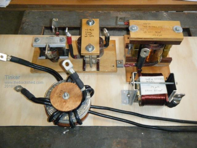 On the picture above, on the left, back row, is the usual E65 ferrite choke that was recommended by the original inverter builders. It has 4 turns of 63mm sq. L=53.8uH Left front row is a ferrite ring core with 2x3 turns of 40mm sq wire (2x20 in parallel). L=56.3uH for each coil. Center, back row, is a choke made from 2 sets of the smaller Aerosharp choke, the C cores arranged to form an E core. It has 9 turns of 45mm sq and a 2mm air gap. L=43.5uH. Right, back row, is a choke made from 2 sets of the larger Aerosharp choke, similarly arranged as above. It has 18 turns of 40mm sq and a 2mm air gap. L=174uH. Front row, right, is my latest choke, made from a single large Aerosharp choke. This one has 11 turns of 60mm sq, a 1mm air gap and L=74uH. First I tested each for the no load, idle power, of the complete inverter, running from the battery. Best was the big dual large Aerosharp C core which used just 10.9W but had small wiggles along the sides of the sine wave. With a 2KW load the sine wave was very good. Next came the single large C core version, 12.3W idle and best sine wave. With a 2KW load there was no observable change in the sine wave, Then the choke made from 2 sets of the smaller C cores, 14.22W idle and a clean sine wave. Under 2KW load the sine wave had a small kink at zero crossing. Second last test was the E65 ferrite core, 12.6W and clean sine at idle. At 2KW the sine wave had a kink at the downslope zero crossing and fuzz on the top & bottom peaks. Last test was the ferrite ring with each winding going to one side of the primary. This had the worst idle at 15.8W and wiggles at the zero crossing of the sine wave. Under a 2KW load there was a distinct kink at the zero crossing and a fuzzy wave at both peaks. So it seems (to me) that using that ferrite E65 core is not the best choice since a rewound single large Aerosharp C core gives better results and much more room for the wire (20 x 70 mm). This is what I will be fitting tomorrow into my large dual stack inverter, replacing the ferrite E core and dual small C core chokes that were in there. It appears that a single choke was better than the combination I had in there. We shall see how that performs under some bigger load. I had used a 1mm air gap which gives 170A (peak) saturation current. This can easily be changed by using a different air gap. If anybody is keen to replicate that choke making I can post some tips how I made mine. Klaus |
||||
renewableMark Guru Joined: 09/12/2017 Location: AustraliaPosts: 1678 |
I remember Poida showed some results to show the ferrite gets rid of some high frequency crap. I used a double stacked (4 pcs) E70 ferrite in series with a double big aerosharp c core. Do some series testing Klaus...... I'm actually surprised you didn't. Cheers Caveman Mark Off grid eastern Melb |
||||
| Tinker Guru Joined: 07/11/2007 Location: AustraliaPosts: 1904 |
I am, with the equipment I have here. Not everybody has a fancy digital oscilloscope that does screen shots. Have you tried your inverter 'without' that ferrite choke? Just the ex Aeroshearp rewound? Klaus |
||||
| renewableMark Guru Joined: 09/12/2017 Location: AustraliaPosts: 1678 |
Hahahahahaha, no bloody way! I have blown up enough crap for a lifetime on this build. There is a perfect wave, torroid and chokes are quiet at all loads tested so I'm going to leave it alone. I only have one inverter so far, so I'm reluctant to mess with something that works. Cheers Caveman Mark Off grid eastern Melb |
||||
| Warpspeed Guru Joined: 09/08/2007 Location: AustraliaPosts: 4406 |
Excellent advice Tinker. There is absolutely no substitute for having a real full sized non saturating choke with sufficient inductance, perhaps 100uH+ for a 48v inverter. Cheers, ĀTony. |
||||
Revlac Guru Joined: 31/12/2016 Location: AustraliaPosts: 961 |
Looks good Tinker  I'm not familiar with Aerosharp parts. Just curious, what is the cross section of the single large C core? (20 x 70 mm) is good room. I have found one C core but it is made from thin sheet like the toroid and I expect results would be different. Cheers Aaron Off The Grid |
||||
| Tinker Guru Joined: 07/11/2007 Location: AustraliaPosts: 1904 |
Aaron, that choke is now hidden inside my big inverter. But from memory, the air gap spacer measured 20x40 (or45)mm. This is, of course, the cross section. I think the reason why this material seems to work better than ferrite is the fine flaky core rather than sheet laminations. The only way to find out what works is to experiment - join the club  . .Klaus |
||||
| Warpspeed Guru Joined: 09/08/2007 Location: AustraliaPosts: 4406 |
The way to do all this is to understand the requirements and select the most suitable material for the job. The flakey sharp core is the silicon (glass like shards) that eat fingers. Its fine unless you try to cut or grind it, then it will turn really nasty and bite you. The reason silicon steel is vastly better than ferrite (for a dc choke) is simply it will take about 5 to 6 times as many ampere turns before it saturates. A second reason is that ferrite gets horribly expensive in the larger sizes, and it would need to be a truly huge piece of ferrite to compete with a much cheaper and smaller silicon steel core. Its difficult to find this information in a form that is easily presented on the Forum, but try this: https://magweb.us/free-bh-curves/ The first two materials on the list "GO" are the grain oriented silicon steels of two slightly different grades. This is what we use in our toroids, and what we SHOULD be using in our chokes as gapped U core halves. This material will work happily at typically 1.6 Teslas and goes into terminal saturation at around 2.0 Teslas. The last material listed is one particular "F" grade of ferrite. That is typically run up to 0.3 Teslas in most applications, and saturates at around 0.35 Teslas. So the Silicon steel will work up to at lest FIVE TIMES the flux density of ferrite before it finally saturates. Experiment all you want, but ferrite is always going to wimp out long before silicon steel in any dc choke. What we want here is enough cross sectional core area, that will give us both sufficient inductance and support sufficient ampere turns, there being a tradeoff between the two. So for a given core cross section, we will have a trade off between inductance and maximum current at saturation. One or the other, depending on the number of turns and the air gap. If we cannot reach both the required inductance and the required maximum dc current, at saturation, we need more core cross sectional area for the choke. ********************* How to come up with a choke that meets our requirements, assuming we are going to recycle some salvaged silicon steel U core halves. First thing is we need a specification for minimum inductance and required maximum continuous dc current. For a 5Kw 48v inverter that might be something like 100uH minimum at 100 dc amps minimum. Our inverter may see short surge loads well beyond 100 amps, so the minimum requirement is just that. Higher choke saturation limit is much safer and adds to the robustness of the inverter.... More inductance manly benefits idling power, but you will reach the point of diminishing returns. So once again, more is better regarding inductance. No hard and fast rules regarding the minimum specifications, but at least we need some idea of where we are headed. The first requirement is pretty easy. The wire must be able to carry 100 amps without melting or bursting into flames. Temperature rise is the key here. The length of the wire will not be huge, so voltage drop is not an important consideration. So we consult wire table like this one: https://www.bluesea.com/resources/529/Allowable_Amperage_in_Conductors_-_Wire_Sizing_Chart And we find that 25mm^2 wire will carry 106 amps at 75C temperature rise. Pretty hot, but not totally unreasonable. As a matter of interest, three metres of that wire will have a resistance of .0172 x 3m divided by 25(mm^2) = .002 ohms It will drop 200mV at 100 amps, bugger all at a 48v supply voltage. And it will dissipate 20 watts, or not much at a 5Kw inverter output. So although its going to get a bit hot, its not a great waste of power. So don't worry too much about the wire in the choke looking a lot thinner than the primary. If you can do it some other way and fit more copper and more turns into the core slot, that is a definite step in the right direction. But for us, it might be more practical to just use fat ugly round wire with much larger cores. Next we work out how many turns of that will fit through the slot in our U core halves, and that will fix our maximum possible number of turns for that physical core size. Next step is to assemble our cores with some known experimental air gap spacers (1.0mm ?) to try experimentally. Our saturation tester will be limited to its maximum design current before it blows up, and that may only be 40 amps peak for example. So to overcome that limitation, we put on a larger number of turns of thinner wire to play around with initially. Suppose we fitted on 30 turns of junk wire and we test the core with that. Suppose hypothetically it goes to 28 amps before it saturates, that is 30t x 28amps = 840 ampere turns. And we can also measure the inductance of those thirty turns from the applied dc voltage and rise time of the current up to its peak. Now lets assume we can only physically fit ten turns of the big 25mm wire on that particular core size. We know that 30 turns saturates at 840 ampere turns. That tells us that 10 turns will saturate at 84 amps, a bit short of what we would like. We know that inductance increases at the rate of turns squared. We tested with 30 turns, but can only fit 10 turns on our core. One third the turns would result in one ninth the inductance. Does that meet our goal of 100uH minimum ? Maybe not... Changing the air gap will change the relationship between saturation and inductance, you can have more of one by sacrificing the other. That may steer you in the right direction. We have 84 amps saturation, if we have way more inductance than we really need, we could increase the saturation limit by making the gap slightly wider. If we have both insufficient saturation and insufficient inductance, the whole core is too small and we need to either add more core halves, or find something larger. By trial and error you should be able to come up with something that is satisfyingly more than the original minimum requirement. Its definitely a case of more being better for both saturation threshold AND inductance. 150uH beats 100uH. And if you can do both 150uH and 150 amps break out the beer.... Cheers, ĀTony. |
||||
| Warpspeed Guru Joined: 09/08/2007 Location: AustraliaPosts: 4406 |
One further thought. Old microwave oven transformer cores might make a respectable inverter choke. I have never tried it. The welds would need to be cut away, possibly with an angle grinder with a very thin slitting disk, so you end up with separated E core and I core halves still welded as solid blocks. Not sure if that is even possible. The Es and Is may be interleaved as in normal transformer construction, and cutting it in half may not work. But knowing how cheap things are made these days, the Es and Is may be just butted together in a jig without interleaving, and welded up quick and dirty. The original windings should then be quite easy to remove with the core halves seperated. Not much room in there, five turns might be about the max. Fit it with an air gap, and see how that goes. The steel used in the core is not great, probably about 1.2 to 1.4 Teslas saturation. Way better than ferrite but not as good as the good silicon steel. But there is a lot of it there, and its free ! There is very limited space for a winding, but one or two microwave oven cores stacked side by side would have a super large core area. Another possibility might be to butt two E core halves together with an air gap,so its then wide enough for ten turns. Well worth a go I think... Cheers, ĀTony. |
||||
| Tinker Guru Joined: 07/11/2007 Location: AustraliaPosts: 1904 |
I quite agree with you there Mark, especially considering the trouble you had getting it going... Good to see that you left the option for another inverter(s). Now that you know what makes them tick the next one will be much easier. And you will be surprised at what these things can tolerate by way of a load if specced generously. Klaus |
||||
| Tinker Guru Joined: 07/11/2007 Location: AustraliaPosts: 1904 |
Thanks Tony for the excellent theory lesson. I'm more of a practical person and much happier to experiment physically rather than with a pencil on paper. So to continue my experiment I fitted the single large ex Aerosharp choke (silicon steel as you say) with 11 turns of 60mmsq wire into my big dual core toroid inverter. I set the gap at 0.8mm. I prefer bigger wire cross sections for the high currents even if the wire length is only from 2.5 - 3m. I wind these coils using three wires of 1.8mm dia. enameled wire, wound simultaneously and can fit 11 turns in the 70mm space available. There are 8 parallel layers of that, adding up to the total of 60mm sq. This makes max available space usage and could not be done with round insulated cable of the same specs. Besides, I have a stack of that wire left over from the original Aerosharp toroid just begging for a use .This choke measured 74uH and saturated at 120 Amp RMS. A bit low but still good for almost 6.5KW. This is the trace at idle. Idle being 35W of which 3W go to the displays of the V/A/W/KWh and the fan temperature controller. 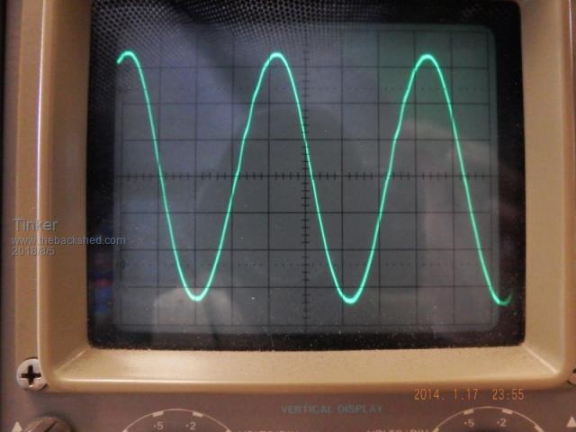 Note there is a small wiggle in the up slope but no zero crossing kink. If there were a ferrite choke as well it would have that zero crossing kink. And this is the trace with a 5.3KW load (100 Amps from my battery). 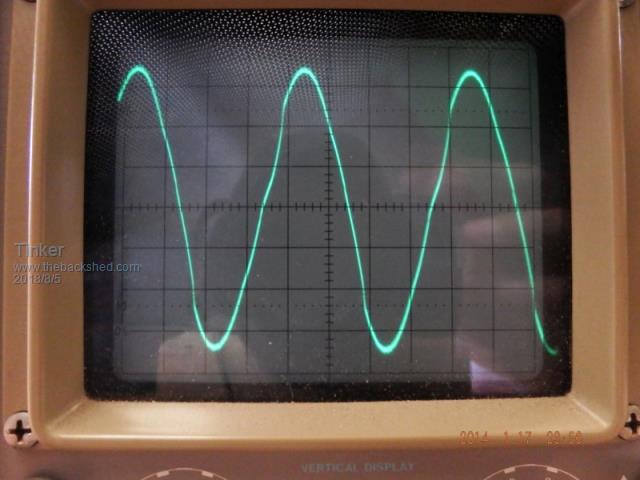 Note there again is no zero crossing kink. I had experimented with my dual large aero C core choke which has 18 turns of 40mm sq wire and a 2.5mm gap. It measured 174uH which is good but the trace from it was not so good looking. So I'm going to wind another coil for the dual large C with just 11 turns, 60 mm sq wire. Doing some testing with my 125 turn test coil for this core I can get the saturation RMS Amps up past 150 with a 1.5mm gap. If the inductance gets above 100uH with that it will get fitted in my dual toroid core inverter. The single C core choke can then fit into my spare single toroid core inverter. I got that choke coil winding sussed out by now too but making the rigid coil former takes more time than winding the 8 layers. Perhaps I should start selling these coils, the labor contend would have to be free though  . . No ferrite chokes any more for me. I suppose we had them because the pioneers of these inverter conversion found ferrite chokes good for reducing the very high idle current of the PJ inverters. And everybody seems to have followed that idea since... Klaus |
||||
| Warpspeed Guru Joined: 09/08/2007 Location: AustraliaPosts: 4406 |
I think that is about it Klaus. The original ferrite chokes were certainly found to considerably lower the idle current, but under reasonable load the inverters were still a lot more stressed than they should have been, if fitted with a much better non saturating choke. The other effect of fitting a much higher inductance choke is to isolate the transformer from the bridge. The transformer becomes decoupled from the PWM sine wave and the transformer starts to "do its own resonant thing". This decoupling is exactly what the choke is supposed to do. It turns the high frequency PWM into a nice clean 50Hz sine wave with very little high frequency ripple at the output. Paradoxically we don't need to design the choke for high frequencies. Skin effect and eddy currents in the core are not going to be a problem if the choke is large enough. So we can use solid copper wire and a steel core. All the high frequency evils are produced by high frequency current, and high frequency PWM current is what the choke is there to eliminate. So we don't need ferrite or fancy winding techniques for the choke. The choke and transformer only see 50Hz sine wave current with very little high frequency ripple that we can ignore. PROVIDED the choke is big enough to do the job. Many people saw the wiggles produced by fitting a larger choke, and just assumed that fitting a bigger choke was causing the problem, and was a backward step. Not so ! The wiggles and kink are introduced by the transformer itself and can only be fixed properly by changing things at the transformer. The kink can probably be fixed with an electrostatic screen, but that is difficult to do properly with a toroid and is not as effective as with a normal shell type E and I transformer. The wiggles can be fixed (or greatly reduced) by very careful resonant tuning of the transformer winding that has the largest number of turns. For a battery off grid inverter that will always be the secondary winding. Commercial grid tie inverters often place this tuning capacitor across a higher voltage primary winding, because it requires a smaller capacitor when connected to the highest inductance winding. Anyhow, its not all magic and voodoo, there are sound practical and theoretical reasons why some things work and other things things do not work out quite so well. All I can do is offer some advice and try to point people in the right direction. Magnetics design is a very deep subject, and I don't want to make it sound more complicated or difficult to do than it really is. The choke is just as important as the transformer in the great scheme of things, its not some added on optional luxury. People have built inverters without a choke and they appear to work. But its painful to think about what really might be going on in those inverters. If you want a sweet running reliable and robust inverter, a good choke is highly recommended. End of rant... Cheers, ĀTony. |
||||
| Tinker Guru Joined: 07/11/2007 Location: AustraliaPosts: 1904 |
Yes, I understand magnetics is a deep subject, one I possibly never will fully fathom. But thanks to your very helpful comments (not a "rant" at all to me)I might be able get this inverter thing working the best I can. And having fun doing it. After all there are now 4 working inverters here, three of which can and have run my house. About that "kink", my large double core inverter does have a good electrostatic screen. That might explain why its not present on this inverter but 'is' visible on my smaller test inverter which has no such screen. I just was not aware what could have caused it. About the "wiggles", my large double core was very carefully tuned to 75 Hz resonance. This was much more obvious to see here than on the smaller test core. I fitted 4.6uF, had to improvise with what caps I had on hand. 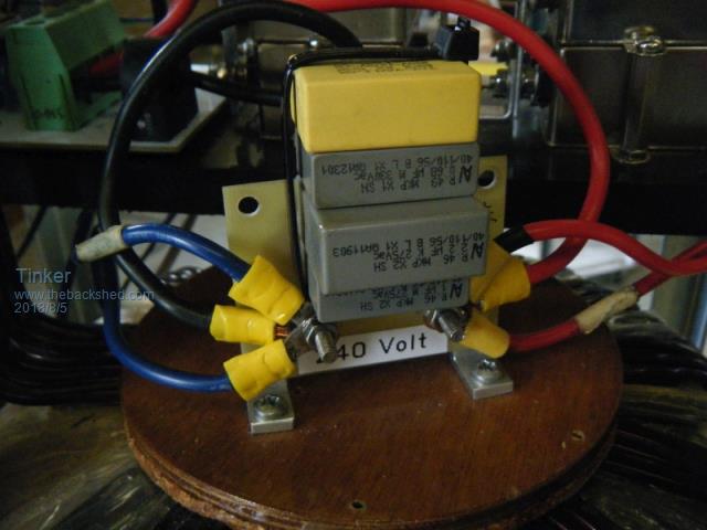 From what little of the "wiggles" is left now under load, I can live with that. So all that's left is to find the optimal inductance for the choke. From my test coil I know I'll have to use at least a 1.5mm gap to get the saturation high enough with the double C core. My winding method allows 11 turns of 60mm sq or 16-18 turns (have to do a trial fit first)of 40 - 45 mm sq. Do you think I'll be better off to do the 16-18 turn first? There is wire enough to do both BTW. I'm still making a strong former to wind it on, the last one had a plastic core and it was hard to get the finished coil off it. I'm now making them from aluminium with a very slight taper so it can slide off easily. Klaus |
||||
| Warpspeed Guru Joined: 09/08/2007 Location: AustraliaPosts: 4406 |
The rule of thumb for getting the most out of any choke core is to fill it right up with as many turns as will fit of minimum sized wire that is not going to dangerously overheat. Then just adjust the air gap for the required balance of inductance and saturation limit. I would use the smaller wire with the 16-18 turns, as that will easily carry the required dc current. Then just tweak the air gap. Cheers, ĀTony. |
||||
| johnmc Senior Member Joined: 21/01/2011 Location: AustraliaPosts: 282 |
Thanks you both Tinker and Warpspeed for effort required to produce the information about the choke, which helps me further understand the operation of the inverter. cheers john johnmc |
||||
| Warpspeed Guru Joined: 09/08/2007 Location: AustraliaPosts: 4406 |
I suppose anyone that has used a couple of those large Aerosharp toroids also has a pair of the larger U core chokes that go with them. That should make an excellent basis for making a suitable choke. Cheers, ĀTony. |
||||
| Tinker Guru Joined: 07/11/2007 Location: AustraliaPosts: 1904 |
You are welcome John, just keep asking until you are confident about what makes these inverters tick. Its the key to success you know Klaus |
||||
| Tinker Guru Joined: 07/11/2007 Location: AustraliaPosts: 1904 |
With regard to that choke 'magic' it might be worth while to re read warpspeed's excellent post. Perhaps a little addition about terms like "saturation" and "air gap" might be helpful for some. From the above link we see what the choke in our inverters is supposed to do. Current flowing through the choke turns creates a magnetic field, the strength of which depends on the number of Amps flowing and on the number of turns the wire makes around the core. Increasing either or both increases the magnetic field. But there is a limit on just how tightly those magnetic lines (flux) can be packed into a given cross section of core material. If trying to create more flux by increasing the Amps beyond a certain point the core "saturates", it can no longer accommodate that extra flux. The result being the choke no longer does its job to smooth excessive current demand spikes if the saturation A/t's are exceeded, putting strain onto the mosfets which have to handle this. What to do? One way is to increase the core cross section area but this is not often practical. But there is a neat other trick to get around that. It so happens that the magnetic flux travels about 10,000 times easier through the core material than through air. So just a very small (relatively) air gap greatly increases the saturation point, allowing for the choke to do its job for a higher current. We measure saturation in Ampere turns (A/t), meaning a one turn coil saturates at so many (100s, 1000s) of Amps. A ten turn coil saturates at 10 times less current, and so on. Now "air gap" can mean that literally but that means shortening the center leg of an E core - not always convenient and not adjustable. But we can fill the gap with material that can take clamping pressure. Of course that means 3 spacer shims for an E core. The requirement for this gap material are: It must be non magnetic (obviously )It must be non conductive (to stop eddy currents heating it up) It must be flat, rigid and able to withstand the temperatures inside an inverter (~60 deg. C) without deforming. In the picture below I show how I arranged the two C core halves, bedded in epoxy, to make a rigid E core so the lot can be clamped together easily. In the foreground are the various gap spacers I selected for different gap sizes. From left to right, 0.9mm bakelite, 1.2mm plastic, 1.5mm plastic, 1.9mm model aircraft ply, 2.4mm (3 layers of formica superglued together. Many other materials might be suitable, I used what I had in my shed. 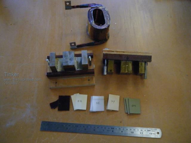 In the background is that 18 turn coil I mentioned earlier in this thread. I'm going to make another one as this one has the connecting lugs arranged so it won't fit into my inverter. So here are my test results for the pictured choke which might give a good ball park figure to those who do not have a suitable test coil nor the required saturation test equipment. Dual large C core choke (cores ex Aerosharp) Core X area 33x45 = 1485mm sq. Area available for the coil 20 x 70 mm Saturation occurred with no air gap: 625A/t 0.9mm gap: 1562.5A/t 1.2mm gap: 1875A/t 1.5mm gap: 2625A/t 1.9mm gap: 3125A/t 2.5mm gap:3750A/t Keep in mind that I had read these values off the graduations on my oscilloscope screen, alas it has no fancy digital value display. Also, it applies *only* to that particular core material, other cores, even if the same cross section, are likely quite different. These currents are the peak values. For the equivalent RMS power calculation divide the A/t by 1.414. Example: 1.5mm gap, 2625A/t, 18 turn coil = 2625/18 = 145.83A peak = 103.3A RMS. 103.3A RMS at 55V battery voltage means at 5672W RMS power draw from the battery the choke begins to saturate. As there are losses involved I would limit that inverter for a steady 240V 5.5KW power draw. If things like fridges, motors etc are plugged in the steady draw should be quite a bit less since the start up current of motors can be 10 times higher (briefly) than the running current. Next post is the same test with two C cores of the smaller Aerosharp choke. As there are two of these in each Aerosharp it might be useful for the single toroid inverter builders. I plan to have one of each arrangement with max # of turns & optimal copper cross section. Testing of these later. Klaus |
||||
| Warpspeed Guru Joined: 09/08/2007 Location: AustraliaPosts: 4406 |
Pure gold Klaus. As a matter of interest, Mark's choke used two sets of those larger Aerosharp cores with about a 1.0 to 1.1mm gap. Difficult to measure exactly as it was all glued together into a solid lump. Anyhow, that would fall about mid way between your 0.9m and 1.2mm measurements. Assuming that can reach about 1,670 ampere turns, with 12 turns that works out to around 139 amps saturation for Marks choke. Those twelve turns produced 125uH. It used 25mm^2 single insulated marine/automotive fine stranded cable of just under 10mm OD. In theory 14 turns should have just fitted into the 20mm x 70mm slot, but in practice 12 turns was the absolute limit. It required I think about 3m of cable. We only had one go at this, and by sheer luck it all worked out very well indeed having pretty well an optimum balance between saturation and inductance with the gap the core already had. A very few extra turns with a slightly larger gap may have been better, but that would have required using something other than the straight off the spool round plastic insulated cable which we already had, and was very easy to try. One winding technique you guys may like to think about would be to cut up some sheet copper into a long strip, maybe 1mm thick and 50mm wide. Wrap that plus a sheet of mylar insulation 70mm wide around the core. The slot is 20mm high, so at least 15 to 18 turns should be possible of 50mm^2 copper. If the copper is first annealed with a blow torch it should become very soft and very easy to work with, especially if each turn is gently hammered flat with a soft hammer where it has to pass through the slot in the core. Cheers, ĀTony. |
||||
| Tinker Guru Joined: 07/11/2007 Location: AustraliaPosts: 1904 |
Interesting idea, that sheet copper winding. It would need to be quite long, 2.5m+ when I look at the new coil former I made today. Then there is the challenge of how to connect to the start of the winding... I have now finished a new winding former for that twin large C core choke, the old one gave me trouble extracting the finished coil. Anyway, from my calculations I should just fit 17 turns of twin 1.8mm dia enamel wire on it. Also 10 layers of that, so 5mm sq x 10 gives me the same 50mm sq area than the copper sheet idea. 2 wires side by side is about the minimum that can be securely clamped at the start. The last coil had 3 wires side by side which clamped nicely. A single wire would result in 34 turns at 25mm sq with this method but clamping the start would be difficult. Its not enough to wrap the start around something, it must be clamped very well for to wind a tight coil on the lathe a fair bit of toolpost 'brake' is required. The new coil will take a while, can only do one layer a day. It should have above 150uH, I'm planning to use the 1.9mm core gap. Klaus |
||||
| Page 1 of 6 |
|||||
