
|
|
Forum Index : Electronics : nanoverter build
| Author | Message | ||||
renewableMark Guru Joined: 09/12/2017 Location: AustraliaPosts: 1678 |
How come we don't do it this way? Cheers Caveman Mark Off grid eastern Melb |
||||
| poida Guru Joined: 02/02/2017 Location: AustraliaPosts: 1389 |
On the second nanoverter board I am building (one for spare #2 for me, one for a friend) I have tested the voltage regulation of the 7812 and 7805. This board has a 7812 that I am almost certain came from RS Components. When one or the other or both fans switch on, the 12V output is a straight line!!! Perfect. And of course the 5V rail is a straight line. Dodgy components bites me again. When will I stop posting all this alarming stuff here. The parts not from RS are not able to do the 1A specified. The RS parts romp it in. Oh Brother. the under performing one is marked L7812CV The reg that works is marked 7812CT (an OnSemi part, from RS) This is getting curious. I checked my Aliexpress order history and I have not bought 7812 regs from them at all. So that rules that out. My other sources are Jaycar, RS and Alltronics I don't want to point the finger at anyone. I think it's more an experience that teaches me to test things before I go full on with the project. Edited 2019-10-22 20:49 by poida wronger than a phone book full of wrong phone numbers |
||||
| renewableMark Guru Joined: 09/12/2017 Location: AustraliaPosts: 1678 |
yeah I thought something must be up as mine has run fine for half a year. Don't forget I gave you some chinese parts from ali xpress smoke. My jcar unit has CDIL LM7812 K7 T JS spec So re power supply to nano, is it better to give it 12v? I still can't calibrate my DC volts on the house machine. Mad's explanation would cover why. Edited 2019-10-22 21:25 by renewableMark Cheers Caveman Mark Off grid eastern Melb |
||||
| poida Guru Joined: 02/02/2017 Location: AustraliaPosts: 1389 |
time for some mug shots the culprit: 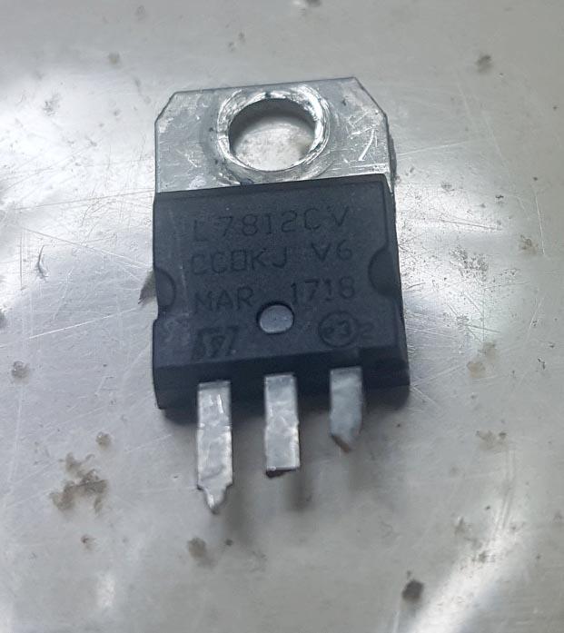 The RS part, with the bag it came in (a 7812 that can produce 0.8A easily) 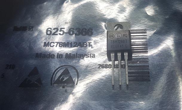 side by side, different package types for sure. The good one is on the right. 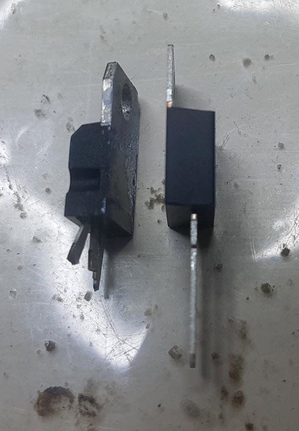 I probably lost sleep over this last night. It's just not worth it for a $2 part from ??? or $0.75 ea in a bag of 5 from RS. The spare nanoverter with the good 7812 still has the 10uF caps on the output of both the 7812 and the 7805. The outputs are good for the loads being 0.8A on the 12V output and about 50mA on the 5V. Straight lines with fans on or off. Edited 2019-10-22 21:31 by poida wronger than a phone book full of wrong phone numbers |
||||
| renewableMark Guru Joined: 09/12/2017 Location: AustraliaPosts: 1678 |
That culprit one you have was one of the Ali exp ones we found were getting too hot. Then we both switched to the jaycar units. You must have got it mixed in with decent parts and used it again. Ali is great for it's pricing but you really can't tell if the part is total rubbish unless some testing is done on every single item which isn't feasible. You could have a bag of 10 and three are good, if you used two good ones from the bag it would be easy to assume the rest were ok, then 12 months down the track you pull out another from that bag and get a dud one. Leaving you chasing your tail on a new build. I stopped buying electro caps from there too after many popped their lid. That's going back to the ozinverter build days. I wonder how many problems were caused by crap parts, I'll never know. Cheers Caveman Mark Off grid eastern Melb |
||||
| renewableMark Guru Joined: 09/12/2017 Location: AustraliaPosts: 1678 |
Now getting back to the power supply for the nano. Currently it's fed with 5v. As Mad pointed out they are recommended to be powered by 12v (diagram at top of this page) Is this something that should be addresses? Cheers Caveman Mark Off grid eastern Melb |
||||
| poida Guru Joined: 02/02/2017 Location: AustraliaPosts: 1389 |
Mark, here is the relevant part of the nano schematic. 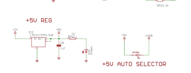 It differs from the UNO board. Vin will pass through a linear regulator to produce 5V. If USB 5V is higher + diode drop, then the USB 5V line will power it. The nanoverter uses the 7805 to produce 5V with is fed into the 2 nano boards via pin 27. When I measure this voltage, I see 4.99V according to the Fluke 87. The schematic shows that the USB 5+ supply has to pass through the diode D1 which will take a bit off the top of the USB 5V should it want to conduct into the 5V supply. And it won't because the 4.99V on pin 27 will be more than the USB 5V minus the diode drop. I measure 5.20V on the USB 5V supply. This is from a powered USB hub. On the other end of the diode I measure 4.81V. The voltage drop through this particular diode is 0.4V So we should expect 1/2 of nothing much to happen to the 5V supply to the nanos (on pin 27) when we plug in the USB connector when the nanoverter board is powered up. And this is confirmed when I probe the 5V on the 7805 output and pin 27 on nano2 when I plug the (powered) USB connector into it. A straight line, even when I turn the vertical gain right up on the DSO. Now, both nano boards have a bootloader running at all times. This will detect when you connect to the nano using a serial console and when you first connect, it will force the nano to reboot. Just plugging in a USB cable will not force a reboot, you need to then connect to the nano via a serial console. I have had no problem with this behavior, even when the inverter is running. What happens when I first connect with a running inverter, to nano2 is it stops immediately (just like the EG8010, when you stop it.) No problem. wronger than a phone book full of wrong phone numbers |
||||
| poida Guru Joined: 02/02/2017 Location: AustraliaPosts: 1389 |
So I did a few tests: First, I bought a 7812 from Jaycar. Then I located the bad 7812 from the Little Box O Horrors* and soldered 3 legs on it. And I found a 7812 sourced from RS Components. A simple test was set up on the bread board, with 10uF caps on input and output and I had the 12V output lead to the DC load I built. (I can't even now accept how useful the DC load is and was) All tests were done with large heat sinks on all 3 7812 linear regulators. Results are in. The RS components part could deliver 1.0 Amp easily and it could deliver it into a sharp load increase, from zero to 1A. It signed off, saying "it's all too hard" under a load of 1.1A or so. It could not get to 1.2A without dropping the voltage to about 2V. The part that gave me lots of trouble (probably some bulk buy from Aliexpress that MArk made and I got to have a few spares) could get to 0.4A and then puke and die, dropping output to less than 3V. Transient load application even at 0.5A resulted in less than 3V output. This is not in spec. The 7812 in TO-220 package should do 1.0A. This one does not even get to 1/2 way there. The Jaycar part was inserted into the test board next. No problems at 1.0A. I could drive it to about 1.4A or so before it signed off, taking it's output voltage down to less than 3V. Transient load applications of well over 1 Amp were fine with this part. The bottom line? Get your commodity parts from proper sources. Clearly, if I wanted 7812 regs, its Jaycar for me. Then RS if I need more than one. I tested the 7812 alternative, when given 15V in and 12 out as the problem... 4 1N4007 diodes in series as suggested by noneyabusiness. Under 1A load they do get warm alright. But something about this suggests to me "bullet proof" and I think I will do this from now on in my new builds. There are two new builds, a spare for me and the first one for a mate of mine. I found a good dc-dc converter to do the job of 60V+ to 15V. The aliexpress links are quite a good one - it's adjustable output.. and this one which might not have enough grunt - fixed output voltages The specified converter is no longer available or you need to contact the supplier to get the 15V output. Too hard. Just buy something else. The Madness powerboard/nanoverter inverter of mine is still running the house. I placed it into service about 31 August and this is a good long test so far. * The Little Box O Horrors is a place where I put all the failures and blown parts. I must have 15 IR2004 gate drive chips there. And bad caps. MOSFETS by the dozen. Blown EGS002 modules. And a very badly dead solid state relay my mate had. And a way overloaded aligator clip lead I smoked. It's wonderful to smell it when you open the box to put the next dead thing inside. It smells of Victory. NO. It smells of Education. That's it. Education. Edited 2019-11-01 18:09 by poida wronger than a phone book full of wrong phone numbers |
||||
| renewableMark Guru Joined: 09/12/2017 Location: AustraliaPosts: 1678 |
Well this hot spell brought out the gremlins. The Jaycar 7812 did handle my setup just fine until recently when everything started to get hotter than normal. Winter running, no problem running the fans, but added heat gave me the dreaded light flicker.............. grrrrrr. I had seen that before, when the voltage regs sh*t themselves the inverter produces unstable voltage and the lights flicker. So..... hell yeah... redneck style I just wired all the fans flat knacker to a spare deep cycle 12v battery. I'll sort out something with a transformer later, priority 1 is to keep the machine running. So, what appeared to be a rock solid combo was proved to be not so solid when the hot weather came. Cheers Caveman Mark Off grid eastern Melb |
||||
| poida Guru Joined: 02/02/2017 Location: AustraliaPosts: 1389 |
Temperature monitoring and control is important and the nanoverter gives us the 2 channels (heat sink and toroid temperature) I like it. Just need to get reliable fan DC supply.. wronger than a phone book full of wrong phone numbers |
||||
| Warpspeed Guru Joined: 09/08/2007 Location: AustraliaPosts: 4406 |
Its a bit crude, but good enough for fans... How about a simple source follower using an HY4008 or some other large mosfet with a decent power dissipation figure. For 12v output, the gate will need a zener about 3.5 volts higher than that down to ground, and a resistor up to the incoming supply. The advantages are that the HY4008 will survive 80v, a three terminal regulator only about 30v. If you need a much more closely regulated output than that, replace the zener with a TL431 with feedback to it coming from the regulated output through a voltage divider of 91K and 24K resistors. Edited 2019-11-01 21:16 by Warpspeed Cheers, �Tony. |
||||
| renewableMark Guru Joined: 09/12/2017 Location: AustraliaPosts: 1678 |
Tony, what do you think about just placing two 7812's in the hole? like here Failing that, Mad has a standalone fan controller. here I have 4 of these Poida if you want one. 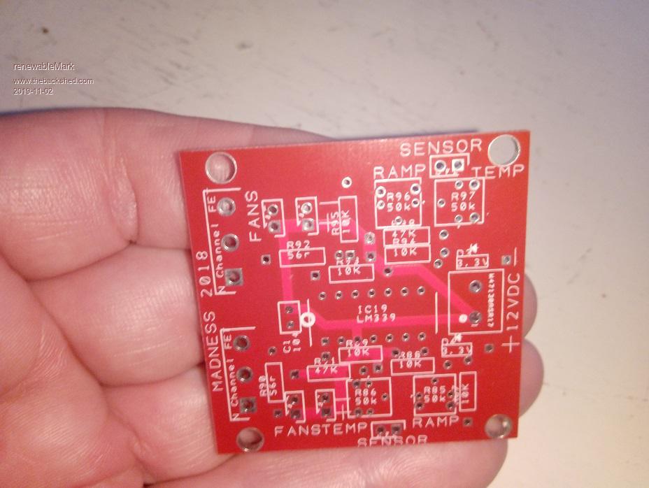 Cheers Caveman Mark Off grid eastern Melb |
||||
| Warpspeed Guru Joined: 09/08/2007 Location: AustraliaPosts: 4406 |
It should be fine if you can find a proper 7812, not some Chinese fake rubbish. And bolt it down onto a man sized heatsink. Cheers, �Tony. |
||||
| wiseguy Guru Joined: 21/06/2018 Location: AustraliaPosts: 1000 |
Poida I was getting set to test my inverter at the weekend and during some final pre-testing I found an issue with the over-current latched shutdown on pin 9 (D6) of my nano1. I am using the nano1 stand alone (no nano2). My over current is an opamp latch driving pin9 (D6), which only achieves 0.6V when trying to drive it high. I had a look at the code to search for anything D6 related and found the following: If I had to guess it would be put a // at the beginning of line 2 and then remove// from line 4. Would this enable the scr shutdown to work and stop it from drawing high current? If not what needs to happen to make it work ? Do I need to also use a statement ie pinMode(6,INPUT); Lastly as there does not seem to be a declaration for D6 why does it become an output (I assume that is why I am having issues, trying to drive an output high when it wants to be low ?) If at first you dont succeed, I suggest you avoid sky diving.... Cheers Mike |
||||
| wiseguy Guru Joined: 21/06/2018 Location: AustraliaPosts: 1000 |
Sorry Mark, just realised I accidentally placed this on your thread instead of Poidas nano thread Do I leave it here or copy it to a more appropriate place ? If at first you dont succeed, I suggest you avoid sky diving.... Cheers Mike |
||||
| poida Guru Joined: 02/02/2017 Location: AustraliaPosts: 1389 |
Mike, it has been a while since I've looked at your project. I assume you are using the code "nano_1_v7_no_bessel_mike.ino" Yes, you probably need to add pinMode(6,INPUT) If you still can not drive D6 HIGH then there is a problem. When not using the SCR shutdown input, you can use if (((PINB & 0x01) == 0) ) � instead of if (((PINB & 0x01) == 0) || ((PIND & 0x40) == 0x40)) When using the former, we only are using D8 as the run/stop command. If it's high, the inverter runs. Using the latter will stop the inverter when D6 goes high OR D8 goes low. The code (PINB & 0x01) is the same as but much faster than digitalRead(8) (PIND & 0x40) is the same as digitalRead(6) (edit) I just checked a few things. I made no pinMode() statements in a program and after booting, the Arduino Nano has about 0.1mA output on a pin. 0.1V. I suppose that is tristate? After I placed the pin to INPUT, the same current and voltage. INPUT_PULLUP applies an internal pull up resistor to the pin's output and I saw 15mA and 5V With pinMode(x,OUTPUT) I saw 80mA which seems a bit high but no worries Edited 2019-11-04 22:26 by poida wronger than a phone book full of wrong phone numbers |
||||
| renewableMark Guru Joined: 09/12/2017 Location: AustraliaPosts: 1678 |
I'm not really fussed about sorting this out right now as the Warpinverter will be the main unit soon, but has anyone used the nanoverter control card to backfeed from a GTI? My setup is a Mad 8Kw power board with nano control card. Latronics edge GTI, (these are the low voltage torroid type) I have two units that are proven to work on mains, but trip with grid fault when used with the nanoverter setup. Actually they work fine when pumping in upto 5 amps DC into the GTI, anything past that and they grid fault. Connected to the grid and they can accept full max power no prob at all. But they will not play ball with the nano card. I have no idea if a different GTI would work or not. So is any one else backfeeding with a GTI and nano? Cheers Caveman Mark Off grid eastern Melb |
||||
mason Regular Member Joined: 07/11/2015 Location: CanadaPosts: 86 |
Hi Mark, is there a how to diagram on connecting the toroid up to the nano board and the power board somewhere on the site, I've been looking but can't find anything. Any help on that would be appreciated. Thanks, Neil |
||||
| renewableMark Guru Joined: 09/12/2017 Location: AustraliaPosts: 1678 |
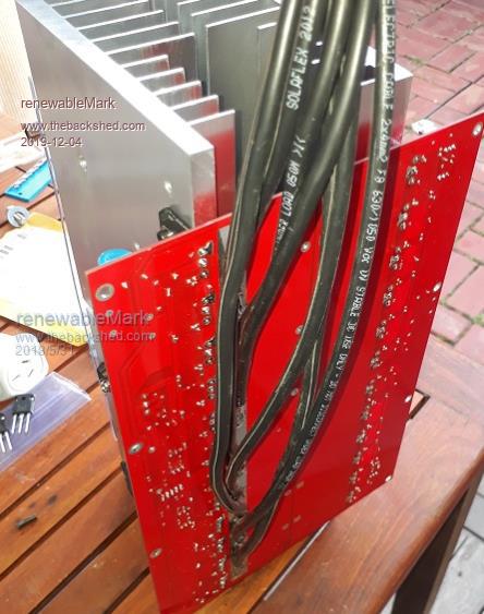
 Wires are different size of course in a proper one, but this is shown to mock up how it goes together. The two wires from the torroid going to the small heat sinks are the primary wires, the lower one needs a choke fitted, (bigger the better) I haven't shown any secondary (240v) connections from the torroid, they will go to the filters and to your output. Pos battery bolts to large heat sink (maybe in two or more places to spread load). Neg battery connects to strip on bottom, you'll need to solder on a few wires and connect them together to spread the load around. Yell out if anything isn't clear Cheers Caveman Mark Off grid eastern Melb |
||||
| renewableMark Guru Joined: 09/12/2017 Location: AustraliaPosts: 1678 |
 Cheers Caveman Mark Off grid eastern Melb |
||||
