
|
|
Forum Index : Electronics : nanoverter build
| Author | Message | ||||
Ralph2k6 Senior Member Joined: 24/09/2017 Location: AustraliaPosts: 129 |
Brilliant work there Mark! Another great build thread, following with interest yet again  Ralph |
||||
renewableMark Guru Joined: 09/12/2017 Location: AustraliaPosts: 1678 |
Thanks Ralph, just remember I haven't got anything to actually work yet. Tinyt, on the build notes item 14 had bat46 for d17,d18. On the silkscreen it has 4148, which one is meant to go there? Cheers Caveman Mark Off grid eastern Melb |
||||
| tinyt Guru Joined: 12/11/2017 Location: United StatesPosts: 431 |
Poor memory, forgot to update the silkscreen, use bat46. It has a lower forward voltage drop than the 1N4148. |
||||
| renewableMark Guru Joined: 09/12/2017 Location: AustraliaPosts: 1678 |
 Thanks Tinyt, all fixed, I initially assembled from the silkscreen, then noticed I hadn't used the bat 46's. Cheers Caveman Mark Off grid eastern Melb |
||||
| renewableMark Guru Joined: 09/12/2017 Location: AustraliaPosts: 1678 |
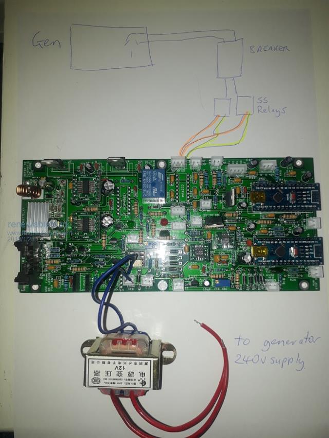 Just checking I am understanding the proposed gen sync connections. Is this drawing correct? And are these relays fit for the purpose here And with the breaker is this OK? Cheers Caveman Mark Off grid eastern Melb |
||||
| tinyt Guru Joined: 12/11/2017 Location: United StatesPosts: 431 |
The transformer connection looks OK to me. J3 only provides mechanical switching signals coming from the on board relay K1. The solid state relays you picked require 3-32vdc to turn it on. So, as connected they will not turn on. If you want them turned on by the code (if the code supports K1 turn on), you will need to modify the PCB slightly. This is bottom side of the PCB. 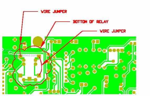 Here is the connection of the solid state relays (input). This will apply +12vdc to the SSRs when the on board relay K1 is turned on. This is top side of the PCB. 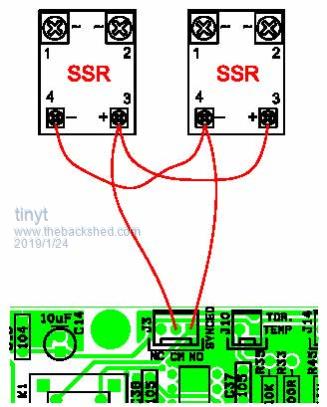 I am not familiar with what you want to happen when the code turns on relay K1. I have not checked the code. Maybe poida can help on this one. |
||||
| renewableMark Guru Joined: 09/12/2017 Location: AustraliaPosts: 1678 |
Thanks again Tinyt, you are a big asset. Cheers Caveman Mark Off grid eastern Melb |
||||
| tinyt Guru Joined: 12/11/2017 Location: United StatesPosts: 431 |
Oops, I made a mistake on the mod drawing, I forgot to mirror the gerber for the bottom view of the pcb. It should look like this: 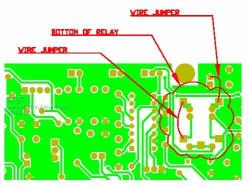 Sorry. |
||||
| poida Guru Joined: 02/02/2017 Location: AustraliaPosts: 1389 |
Mark, thanks for dropping off a bag of components (spares from your build). These will be a great help. The mains sync function: once the inverter output is in phase with the "mains/generator" sync input, D4 on Nano1 will go high, driving the relay K1 to close a normally open terminal to it's common terminal. One use of this might be to add the inverter output to a generator's output. The way I see it working is the generator is already running, with a load on it, taking it's output voltage down a bit. The inverter fires up and syncs, then we can parallel the inverter with the generator. The voltage will now come up a bit thanks to the added current from the inverter. How to wire it: First need to make sure of the phase of the "mains" or generator sync input. The inverter will sync up and we need to see if we guessed the phase wiring of the 240V-12V transformer correctly. I posted before how to find out safely. It will be 180 deg out or less than 2 degrees out. We need to have it less than 2 deg Assuming we have the inverter and the 240V source for the 240V-12V transformer, we can now consider connecting the inverter output to the generator. I would connect neutral of both generator and inverter together. I would connect the inverter active to the generator active via a contact breaker and then a SSR or normal relay. (I still don't believe it will work..) This idea of sync to another source is just experimental. Please be careful out there. wronger than a phone book full of wrong phone numbers |
||||
| poida Guru Joined: 02/02/2017 Location: AustraliaPosts: 1389 |
Mark, I have at last made a start on a board. First get power supply going, then passives around nano1 and the 2 Vfb opamps, put the opamps on to the 0.1" breakout boards you thoughtfully supplied me. Maybe tomorrow I apply power, first without opamps and nano1, then fit those 3 items and see if it lives. I need to get to Jaycar for 15K and other resistors tho. 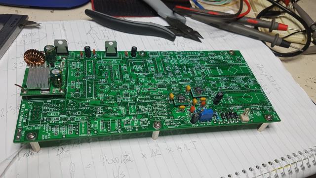 wronger than a phone book full of wrong phone numbers |
||||
| renewableMark Guru Joined: 09/12/2017 Location: AustraliaPosts: 1678 |
Good stuff Poida, I was hoping to finish off my 2nd Mad inverter on the weekend, but it was 36c, then 39c, I can only work outside under the pergola now, so it was just too bloody hot. When that's all confirmed running it will be a good recipient for this board. It would be great to have a checklist of things to go through when powering up the control card. I know you have had a hectic schedule, so just when you have free time, no pressure. Cheers Caveman Mark Off grid eastern Melb |
||||
| poida Guru Joined: 02/02/2017 Location: AustraliaPosts: 1389 |
it lives!, Igor, it lives! 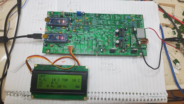 bare minimum: 5V and 12V regs inverter "RUN" green LED nano 5v supply, ADC Vref the two AC Vfb opamps the two IR 21844 sockets and charge pump, decoupling caps I2C A few 2 pin connectors The pic shows calibrated DC V supply at 28V from the bench PS. Later I run it in anger.. wronger than a phone book full of wrong phone numbers |
||||
| renewableMark Guru Joined: 09/12/2017 Location: AustraliaPosts: 1678 |
Good stuff Poida, are you able to post the sketches required for nano and lcd? Cheers Caveman Mark Off grid eastern Melb |
||||
| poida Guru Joined: 02/02/2017 Location: AustraliaPosts: 1389 |
And I have it running the test inverter now. It was a fiddle getting Vfb right. My Vfb transformer is a 9V, not a 12V as specified. I attach the most recent code. I changed the AC output setpoint, to a smaller value to reflect my 9V transformer. When anyone here builds one of these boards, we will need to talk about how to get a reasonable setting for R31, Vfb adjustment trimpot. There is ample scope to try running the inverter with Vfb trimpot set to output 300V and that will blow stuff up. It is best to have it set to about 180V and when running, adjust it up to the desired output voltage. The first attempt was without the shutdown transistor network in place. This permitted the gate drive ICs to float their shutdown pins. Naturally, the inverter was unhappy. But after putting Q1-4 and the resistors in place, it runs really well. The Gate drive output is disabled upon power up to the DC-DC converter. Also they are disabled until you switch the board ON. This is perfect. No spurious gate drive during DC supply ON or OFF. The output waveform, zero load, 27.4V DC supply. 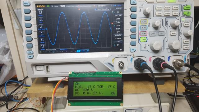 Here is the transient response when I switch 150W incandescent light on. (my standard test load for the bench setup) This is very good transient response to my mind. It is very similar to my previous 2 prototype boards. 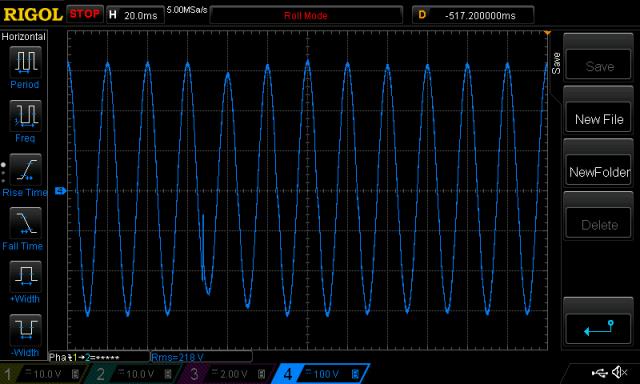 Here it is with the same transient test, on the same inverter, but using a EGS002 to drive it. How they get it to respond so fast, I have no idea. I can change from the nanoverter to an EGS002 in about 60 seconds. 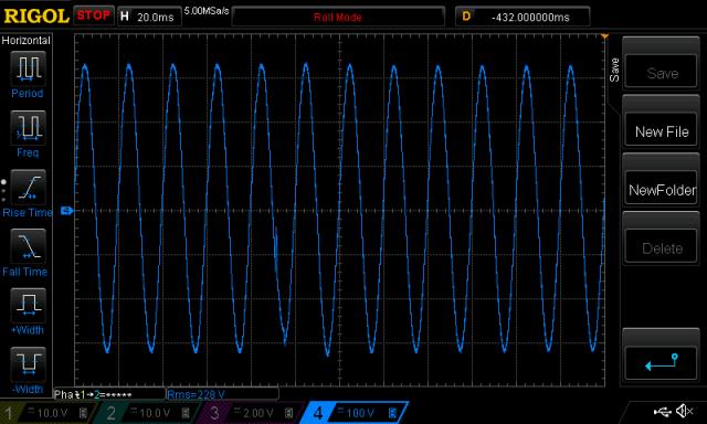 Tinyt: The board has zero errors in the areas I have built. This is a credit to your efforts and skills. Thank you for your work and keen attitude in this project, I know I could not design and build this circuit board in a million years. renewablemark: Thanks heaps for the bag of goodies. Your dropping it off to my house was the kickstart I needed to get building and testing. The latest code: 2019-02-10_230241_Archive.zip Note that this code expects about 10V out of the transformer, not 12 or 13V. Using a 12V transformer will be fine. It's just a matter of the trimpot setting. I successfully uploaded to both nanos by connecting to one, uploading it's code, then connecting to the other... The cheap Chinese clones are a little different to genuine items. I needed to choose under "processor" ATMega328P (Old Bootloader) for the upload to work. This is due to the choice of USB chip they installed. On my imac, no drivers are needed. Just download the arduino program, install a library "LiquidCrystal PCF8574" and it should work. On a PC, you will need to get the latest CH340C drivers (USB chip). It's not a drama. Later I will build a zip file with the needed library and drivers. wronger than a phone book full of wrong phone numbers |
||||
| tinyt Guru Joined: 12/11/2017 Location: United StatesPosts: 431 |
It was not me alone, It was the contribution of everybody here that did the "PDR and CDR and everything in between" of the schematic that made this possible. Thanks to you for sharing your code. Now others can have a hardware platform to use it. |
||||
| poida Guru Joined: 02/02/2017 Location: AustraliaPosts: 1389 |
I have mains sync working too. It's nice to see the LED light up and hear the relay click when sync is obtained. Blue is AC output from nanoverter Yellow is external mains as applied to J2. 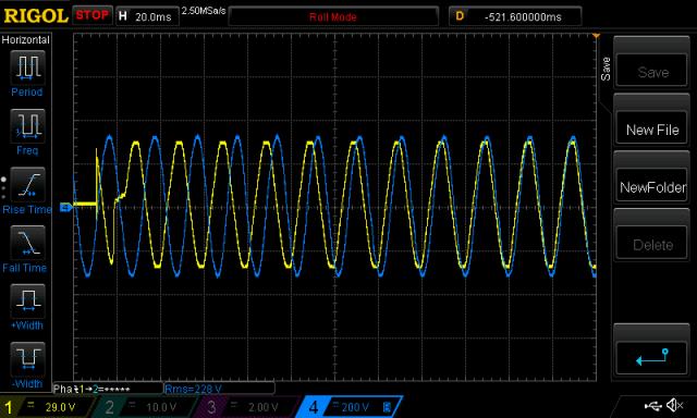 It only needed 11 cycles to shift the output nearly 180 degrees. My external mains isolation transformer is not 12V it's 30V. And so I applied 30V to the 680R + 1N4007 + TLP523 opto. What was that smell? No harm done. I added a 1K in series to reduce the current. All good. wronger than a phone book full of wrong phone numbers |
||||
mackoffgrid Guru Joined: 13/03/2017 Location: AustraliaPosts: 460 |
Poida, looks really good. Regarding transient response, since its the same hardware suggests to me that the egs002 must be do intra-cycle correction? Or could it be the using a different mode of driving the H-bridge? Cheers Andrew |
||||
| johnmc Senior Member Joined: 21/01/2011 Location: AustraliaPosts: 282 |
Good day Poida, Thanks for the pics, it really is looking great. cheers john johnmc |
||||
| poida Guru Joined: 02/02/2017 Location: AustraliaPosts: 1389 |
Mackoffgrid, I do suspect the EGS002 is doing it different. The transient response is not a big deal to me at this stage. I have yet to see any problems that must be dealt with due to this. It's also my way to avoid the issue. wronger than a phone book full of wrong phone numbers |
||||
| poida Guru Joined: 02/02/2017 Location: AustraliaPosts: 1389 |
I have made a change to the mains sync code which brings much better tracking. "Better" in this case is smaller changes to the output waveform during changes in output frequency. I can do it with better resolution. Compared with the v3 code, the oscilloscope trace looks beautiful. Once I test and possibly refine it further, I will post v4 code for nano1. wronger than a phone book full of wrong phone numbers |
||||
