
|
|
Forum Index : Electronics : Poidas "Inverter Software Control" Topic.
| Author | Message | ||||
| poida Guru Joined: 02/02/2017 Location: AustraliaPosts: 1389 |
I can show primary circuit current on the DSO easily. Since the DSO can do maths on trace data, would the integral of the current over time be of any use? I think so, assuming similar response from the core from +ve and -ve current. (But to me, that is a big assumption, I suspect some cores have a little remanence one way or the other) Putting a HE sensor in there is also possible, but I would end up using an EI transformer where you can put a gap in one of the outer slabs of the E with an angle grinder, large enough for the HE sensor. wronger than a phone book full of wrong phone numbers |
||||
| Warpspeed Guru Joined: 09/08/2007 Location: AustraliaPosts: 4406 |
This is yet another reason why I get a bee in my bonnet about designing inverter transformers to have an abnormally low design flux density. It not only reduces idling power and removes the massive turn on surge you often see with these large toroids, it gives a bit more head room if the remnant flux starts to wander around a bit. As mentioned earlier, the switch mode power guys know all about this particular problem, and the simple fix is either to use a series capacitor in the primary, or to use current mode control which is now pretty standard for for new designs of forward converters. None of which helps us with OUR problem. With a purely hardware design, a very fast cycle by cycle current limit should work, which is what current mode control actually does. With software its not quite so easy to be fast enough to do it that way, but I suppose its possible. I get around the problem in the Warpverter by hard switching my transformers direct from a very low impedance power rail. If the mosfet switching times are identical between half cycles the transformers will take care of themselves (pretty much) with identical volt microseconds swing either way. This works, even if the loading on the secondary is highly asymmetrical. With high frequency PWM the necessity for a choke to isolate the switching bridge from the transformer, solves a great many problems, but also creates a few new ones. The microseconds may be the same, but the volts may not be if there is any significant series impedance and voltage drop involved between power rail and primary. The only practical solution I can think of right now, might be to use a flip flop connected to the shutdown pin on the IR21xx isolated gate driver chip. set the flip flop at the leading edge of every PWM cycle, and use a fast current sensor and flip flop reset to cut the PWM cycle short if peak current into the transformer primary is ever reached. That will flat top the sine wave on the high current half cycles and hopefully slew the flux swing away from the saturated condition. Cheers, �Tony. |
||||
| poida Guru Joined: 02/02/2017 Location: AustraliaPosts: 1389 |
I just completed a little test. I think it's quite interesting, relating to the unbalanced load issue. I refer you to the nanoverter modulation scheme, where one 1/2 bridge output does a 1/2 wave, while the other stays at ground, then vice versa.  I try, with some success to ensure that both V1 and V2 outputs are the same magnitude in the development of the code. They are within about 1 part in 500, in my case of the test inverter on the bench. I modified nano1 code to permit the addition of a bias to the magnitude of V1 and also to apply the negative of this bias to V2, via a potentiometer. This now permits me to simulate a very small 1/2 wave diode effect. Not a complete diode, just maybe 5% of a diode effect on one half wave. What happens? Time for more DSO captures, they really tell a story. Light Blue is bias, zero = centered on screen. Pink is primary current. Dark Blue is AC output voltage. The trigger point is the same in all images, a negative zero crossing of the AC output. First is zero bias, showing a nice AC output and the typical leading current. 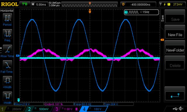 Next is 5 counts of bias, so that means V1 is now (485 + 5) in power and V2 is (485 - 5) power. this is approx. 1% more for V1 and -1% for V2. 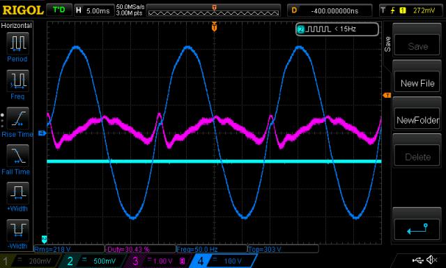 Immediately you can see the effect. A clear increase in primary current on one 1/2 cycle. Note: These DSO captures are under a steady state, which persisted for as long as I wanted/needed to obtain the data. Next is 10 counts bias. Huge. This is what +/- 2% does.  Here is 15 counts or +/- 3% unbalance in AC waveform. 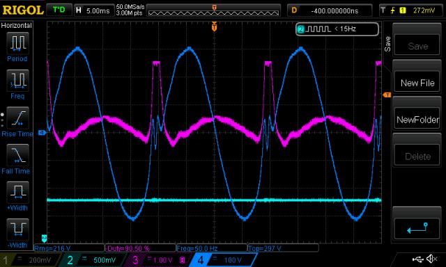 The primary current sensor maxes out at 80A and it's maxed out now. Imagine what 1000W pulled from 1/2 wave would mean.... This is when the wife's hair dryer is running. And I went the other way. We see practically identical results, but on the other 1/2 wave. -5, -10 and -15 bias... 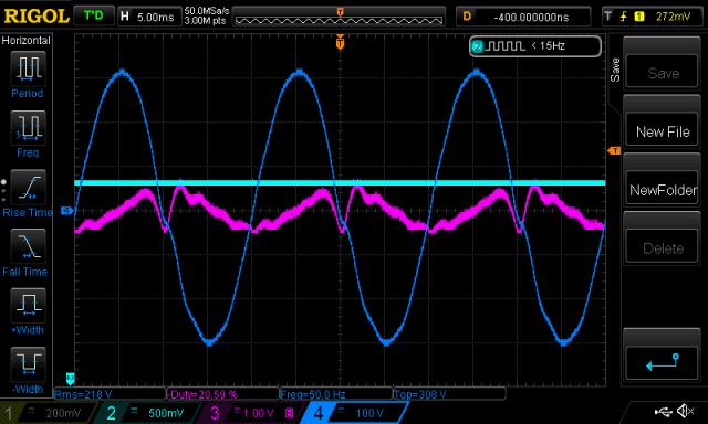   DC supply current: 0 bias, 0.31A @ 27V 5 bias, 0.37A 10 bias, 0.45A 15 bias, 0.83A The same for negative bias. The magic number 485 is the number of clocks the duty cycle would be ON, when at the peak of the 1/2 sine wave. I have a primary winding on the toroid such that I only need this much duty cycle to obtain 230V AC output. Maximum power is 800 clocks. I measure the primary winding is running at about 12.6V RMS from a 27V DC supply. wronger than a phone book full of wrong phone numbers |
||||
renewableMark Guru Joined: 09/12/2017 Location: AustraliaPosts: 1678 |
What would happen if you doubled or quadrupled the caps on the power board with the same tests? Cheers Caveman Mark Off grid eastern Melb |
||||
| Warpspeed Guru Joined: 09/08/2007 Location: AustraliaPosts: 4406 |
Mark, it would probably make the nasty current spike even larger. What I find fascinating is the kink in the voltage waveform, but only on one side. That kink looks awfully familiar from many of the inverter output waveforms we have seen posted here. If the kink is on both sides, its probably more likely due to capacitive coupling between primary and secondary when using unipolar drive. But I could never figure out how it can only occur on only one side. Now we know ! One thing seems particularly strange. The spike on the pink waveform reverses direction. It goes positive on the negative current half cycle, and negative on the positive current half cycle. I would not have expected that reversal. What to do about it is another matter entirely. Cheers, �Tony. |
||||
| Warpspeed Guru Joined: 09/08/2007 Location: AustraliaPosts: 4406 |
I have no idea if this would work, but how about an ordinary current transformer in the primary, with the CT secondary connected directly across a fairly large capacitor. Current flow from the CT would alternately charge and discharge the capacitor each half cycle, and if the half cycle current integrals were identical, the net dc voltage on the capacitor would be zero, with perhaps just a slight ripple. This would be extremely sensitive, and the voltage on the capacitor could possibly staircase upwards to an inconveniently high voltage when driven from a pure current source such as a CT. The capacitor voltage would probably need to be clamped to some safe maximum value, but it might(?) potentially be useful to steer Poida's symmetry software. Cheers, �Tony. |
||||
| wiseguy Guru Joined: 21/06/2018 Location: AustraliaPosts: 1001 |
Poida - what can I say ? brilliant ! That is what I saw in my mind without the CRO pictures to back it up though. That is why I stopped the variac at 120V (heading for 240V) when the idling current rapidly increased by a factor of ~ 10 times - I didnt want to have stuff go bang in my face. This is also why we need to get the feedback right so there can be no unidirectional racheting of the magnetising current. It might also help to explain some of the sine wave distortions that we have seen but not totally understood. I am wondering if a true RMS rectifier/feedback might work better, for our inverters and also to slow down the response. If we try to correct too quickly for a momentary turn on surge or similar there is a possibility for the feedback to over correct, and if driving something with a half wave component, the feedback could ratchet the drive in one direction. I guess I am saying perhaps it isn't really the load that is the problem per se, is it misleading feedback information of VFB that is lying to the micro about what it needs to do and when to restore equilibrium, and in some cases can tend towards the opposite direction ? An inverter is not really like an overgrown Class D audio amplifier with feedback to stabilise it, where the worst that can happen is you have to go look for the voice coil after a serious overload, a toroidal is a much nastier load than some big arse speaker........ If at first you dont succeed, I suggest you avoid sky diving.... Cheers Mike |
||||
| Solar Mike Guru Joined: 08/02/2015 Location: New ZealandPosts: 1127 |
Poida, excellent work there. Perhaps we could use two feed back mechanisms or loops. 1: use the DC battery voltage in a fast response per cycle loop. 2: use the rectified, LP filtered AC output in a slower response loop over tens of mains cycles. Cheers Mike |
||||
| wiseguy Guru Joined: 21/06/2018 Location: AustraliaPosts: 1001 |
Poida, could you please run an experiment and publish the results here if you have the time ? Can you please set up a test where the inverter does not have any feedback and is running open loop at say 230 or 240V. Then load it at 25% 50% 75% and 100% of max (dont over load it, just to some safe value) ? What I am looking for is the input VDC measurement and the corresponding output ACV for the above % loadings. I dont have a feel yet as to the amount of droop the output has under load. I would expect the toroidal secondary impedance and the primary choke to be the 2 x biggest contributors to droop, followed by FET's and then input impedance. Please measure input volts as close to the output FETs as possible to be more meaningful and the AC Volts as close to the toroidal output winding as possible. I have some ideas but need this info to form & shape them better. It will be at least 3 to 4 weeks before I can do these tests on my own inverter.... sigh. If at first you dont succeed, I suggest you avoid sky diving.... Cheers Mike |
||||
| wiseguy Guru Joined: 21/06/2018 Location: AustraliaPosts: 1001 |
This is along the lines of my thinking. VFB is needed as it enables us to set the output voltage at say 240VAC. This may be with the secondary unloaded or loaded to some arbitrary value say 50%. I am beginning to think that the inverter output voltage accuracy is not at all important in the scheme of things once initially set up - as Poida rightly points out, the real mains is horrible and I know first hand it can easily be up or down 10 volts at any given hour of the day, some times within minutes it can vary that much. So to have a reasonable accuracy, perhaps near instantaneous response is maybe not a great feature, especially for difficult loads (ie Marks air conditioner) having no feedback and an arbitrary output setting at say 230V might have better stability and a nicer waveform than with fast responding feedback applied. Yes feed-forward from the battery voltage could probably work quite well. It should be sensed close to the FETs and I don't think minute adjustments are required and possibly might cause problems too, it could probably adjust quite well with discrete steps of 0.1V or even 0.25V. Input current is also another available indicator of output load and therefore voltage. Of course VFB is the most accurate method to set output voltage but I think an RMS chip with a slow response of say 100mS or 250mSec might be a lot more stable than a fast response. Lastly Warps idea of looking at the toroidal primary current with a suitable current transformer has some attraction. If we put 2 comparator circuits to detect the beginning of saturation in both directions we could steer the toroidal drive to stay reasonably centred. Perhaps a test program could be run to purposely find the + & - limits, once we know the count difference, whenever a comparator is triggered we can recentre the the drive by adding or taking half the total count from the drive PWM as required, bringing the 50Hz flux back near the centre ? I know it sounds a bit too much like a flux capacitor..... Just throwing some more ideas out there to think about. If at first you dont succeed, I suggest you avoid sky diving.... Cheers Mike |
||||
| Warpspeed Guru Joined: 09/08/2007 Location: AustraliaPosts: 4406 |
The Warpverter uses no voltage feedback, only direct input voltage correction every second mains cycle (at 25Hz). The dual slope analog to digital converter I used says in the application notes that the maximum conversion rate is 30 per second, so that is how I built the prototype. I have played around with this a bit, and there are a few potential difficulties in measuring the dc voltage. The first is noise, and the best (hardware) solution was the integrating type of a/d converter that averages out any noise over the measurement period. Its fast and accurate, and pretty much immune to random glitches and spikes on the dc, especially as it runs synchronously with the inverter. The second problem is that many types of a/d converters have a one bit ambiguity. Its possible that the LSB annoyingly random toggles, causing the inverter output to bounce up and down. Not by much, and you would probably never notice it unless looking at the output with a CRO. I get out of that by using a 12 bit converter and only using the highest 9 bits. The first three LSBs remain unused and they can bounce around all they like. The inverter output remains rock solid and steps up and down through the lookup tables as required, very positively without any hesitation or jumping around. It all now works so well, I never even bothered trying to force it up to 50 conversions per second, which it may actually be quite capable of doing. Final output voltage adjustment, is by giving the voltage divider that measures the incoming dc voltage some small adjustment range. No need to do anything at all in software. Just step change the gain at the zero crossing point every cycle or second cycle, and input voltage correction will be total, and can never take longer than 20mS or 40mS. Typical correction times should be about half that. My static load droop is very close to 2 volts per Kw of loading, and that too has proved to work sufficiently well in practice. I just cannot justify the extra components and complication to add a slow corrective voltage feedback for no really obvious advantage. By keeping things very simple, there is far less to go wrong ! All of the above would be applicable to a PWM software program, and should work pretty much exactly the same as with a Warpverter. Both are just single stage very high power direct digital to analog conversion. Anyhow, with regard to the current transformer idea, it should work as long as the main toroid goes into saturation before the current transformer core goes into saturation. The way to ensure that never happens is to clamp the maximum output voltage of the current transformer with a pair of back to back series zeners, or better still a transient voltage suppressor, or something similar. Current transformers always have a specified maximum output voltage which is usually between about one and ten volts, and that is to guarantee some kind of quoted accuracy. It should safely go a fair bit higher than that, before it actually falls flat on its face from terminal core saturation. The current rating of a CT has to do with the number of turns and how much current the secondary wire can continuously carry. For example, a 100 amp CT with 1,000 turns will have a secondary winding capable of carrying 100mA continuously without overheating. It will happily and accurately measure current spikes that are vastly higher than that, its the wire heating in the CT we need to be aware of. Another thing to watch out for is that many CTs that have fewer turns are designed for monitoring switching power supplies up in the Khz region and do not work at all well at 50Hz. They use an inferior core material, that gives far less inductance, and are designed to have sub microsecond response to over current events, rather than low frequency accuracy. The better type of CT will have 1,000 turns, be made to work with a high measurement accuracy at 50Hz and will usually be be physically larger. If trying out this current transformer idea, its fairly important to use a current transformer that is suitable, as many of the Chinese cheapies are just not going to be up to the job. I have bought quite a few of these at different times from e-bay, and the specifications cannot always be relied upon. They sometimes say suitable for 50Hz when they definitely are not, or say nothing at all about the frequency range or the inductance. Having an odd selection of CTs on hand to choose from here, can be very useful, and I can usually find something that works much better than the others for a particular purpose. So if trying out these ideas, and the results do not turn out so well, it could be that the CT is unsuitable, and a different CT will give completely different results. One final thought. If our CT output current is say +/- 100mA, its going to take a mighty large capacitor to integrate out the 50Hz ripple voltage. Trying to find a CT with more than 1,000 turns may be difficult. I see no reason why we could not stack two CTs in series, say 100 turns and 100 turns to have an overall ratio of 10,000 or more. That way, we should be able to get away with a more sane integrating capacitor value. There is a second advantage in doing this. The first CT would be looking into almost a dead short, and that would be excellent for minimising the core saturation problem in the first CT. Cheers, �Tony. |
||||
plover Guru Joined: 18/04/2013 Location: AustraliaPosts: 302 |
Members are building chokes, toroidal transformers so would building a current transformer be a possible option?. Hardly knowing anything practical about CTs myself I am just curious if it is too hard? |
||||
| Warpspeed Guru Joined: 09/08/2007 Location: AustraliaPosts: 4406 |
Possible, yes. Practical, no. You would have to buy a new core, because a good low frequency current transformer requires a very high inductance for best results. Its not likely you can salvage a suitable junk core from anything other than another current transformer. Winding on a thousand turns plus, of extremely fine wire is also something I would rather leave to a high speed machine. As you can probably buy a real current transformer for less than twenty dollars, why even bother ? Just quickly skimming through e-bay, there is this : https://www.ebay.com.au/itm/Precision-AC-current-transformer-coil-100A-20mA/273706319521?hash=item3fba2afea1:g:a0EAAOSwq pFcaQi5 100A/20mA (5,000 turns) and its the low frequency type (20Hz). Cannot guarantee it will work, but looks promising. Cheers, �Tony. |
||||
| poida Guru Joined: 02/02/2017 Location: AustraliaPosts: 1389 |
no problem. See attached excel file. I performed it at 2 input voltages. 60V was supplied by a 1500VA EI transformer with unregulated output. There was some ripple on this, as can be seen below. Maybe +/- 0.7V Light Blue is DC in, from the unreg supply. Dark Blue is AC out, Pink is primary current (inverted, sorry)  I also did it at 27.6V, with 2 x 6A regulated supplies, plus my hacked up 5A regulated supply. Input voltage could be maintained for the duration of the testing at all 4 power levels. I buffered the supply with 100Ah 24V SLA battery. AC loads were derived from 4 x Phillips "100W" floodlights. (I went to Bunnings to get the 4 globes, 4 sockets, a 4x light switch, cable, etc. Bolted it together on a board, screwed it under the workbench. Now I have my new and improved test load. Thanks for the needed push in that direction!) Loads were 0, 87W, 166W, 239W and 304W. When at 239W, it was running at 92% efficiency, according to the DC supply current sensor fitted to the nanoverter. Not too bad. Testing notes: nanoverter board, running the current versions. The toroid is one of the two fitted to a Victron 3000VA inverter. I used a Power-Mate Lite meter to obtain AC voltage and AC current. DC supply voltage from a Fluke 87, set to DC. How to obtain meaning from a DC supply, carrying some AC component? The Fluke 87 when set to DC and given a 4V DC signal with 2V peak to peak AC displays 4.00V. Switched to AC input and it shows 0.724V AC RMS. This is close enough, it should be 0.707 (1/square root(2)). So the meter can show either all the DC or all the AC. It does not mix the two. 2019-06-01_135830_wiseguys_test.xls.zip wronger than a phone book full of wrong phone numbers |
||||
| wiseguy Guru Joined: 21/06/2018 Location: AustraliaPosts: 1001 |
I have an excess quantity of brand new current transformers with a 300mm flying lead connection from an earlier project. The make is Taehwatrans the model is TLS76L1. Their rated current is 300A, the max current is 432A and they are a 2500:1 ratio. I think they should be very suitable for experimentation along the lines being discussed here - and a lot cheaper than $12.50 each for the 100A units on ebay. I am happy to make them available at a very discounted rate to any of the back shed members who wants some. I reckon 1 for $10, 2 for $15 or 4 for $25 including postage. Sorry for the one off price - its the nuisance value..... Their dimensions are 37mmOD 13mmID 13.5mm deep weight 40gm.  Graphs for various burden resistors @ various currents for related output voltages 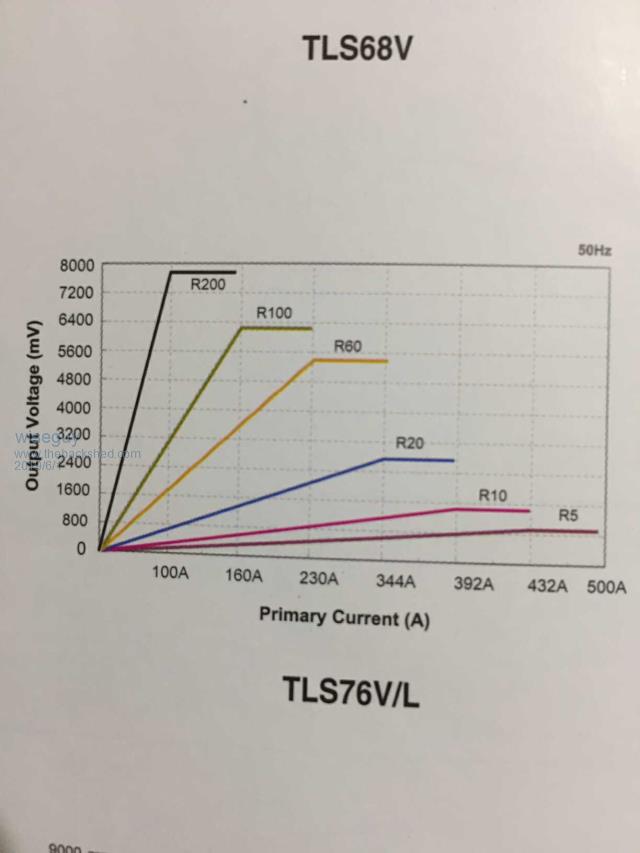 Ignore the asterix for the TLS77 type in the pdf below, you want the second one below it, the TLS76 2019-06-01_142023_Scanbot_1_Jun_2019_13.39_s.pdf If at first you dont succeed, I suggest you avoid sky diving.... Cheers Mike |
||||
| wiseguy Guru Joined: 21/06/2018 Location: AustraliaPosts: 1001 |
Poida, thanks for the test results - they are very revealing. The first glaringly obvious detail is the output droop when there is no correction applied - regulation is much worse than I expected at around 13% at 27.6V and 13.3% at 60V (input variation at 27.6V was ~ 2% and ~ 8% at 60v). I note that the current increase in both cases was of the order of 300% and the magnitude of current in the 60V test was half that in the 27.6V test so resistive losses contribution would appear to be quite minor in the scheme of things. The next interesting detail is the primary current at no load - 10ARMS, yet the actual battery DC input current is no doubt very small. I believe what we are seeing is the charging up current for the AC capacitor on the rising voltage waveform and then recovering that energy back into the supply for the falling part of the wave form. It appears there is ~ 300W of circulating energy not doing any real work yet. I invite professor Warp to head me back in the right direction if I have made a wrong assumption/s here. I think the light blue waveform is also inverted (it may be just the input ripple - not sure), the "furriness" every second cycle I guess is switching noise from the primary side that the sensor is attached to, where every second 180 degrees the other side does the switching so the furriness goes during that part. There definitely needs to be a compensation correction for the output droop but what form will give us the best results is the nagging question and a work in progress. With the high circulating currents (even unloaded) in the toroidal primary I am not confident that sensing current there will help us as much as I hoped. Going back to fundamentals, the transformer simply wants to see an ac waveform with an amplitude p-p that does not cause saturation. If the 50Hz p-p drive to the Toroidal is balanced with no net DC component and the voltage correction feedback does not introduce any unintended p-p offset then we should not have a problem - I invite comments ? If at first you dont succeed, I suggest you avoid sky diving.... Cheers Mike |
||||
| Warpspeed Guru Joined: 09/08/2007 Location: AustraliaPosts: 4406 |
[quote] The next interesting detail is the primary current at no load - 10ARMS, yet the actual battery DC input current is no doubt very small. I believe what we are seeing is the charging up current for the AC capacitor on the rising voltage waveform and then recovering that energy back into the supply for the falling part of the wave form.[/quote] This effect has always fascinated me too. The inductive part of the transformer just circulates reactive energy back and forth without very much net loss. If the transformer is tuned with a fearsomly large capacitor to 75Hz (or some other frequency), that too has a much smaller effect in idling power than might be expected. I think we can assume that reactive power is pretty harmless in itself, as long as it has somewhere to go. If it has a return path back to the dc bus there will be very little real energy loss. The inductance tester is a classic example of that, where you can see repetitive current peaks of many tens of amps, but the dc supply may be only a couple of amps of make up current to cover the conduction losses. [quote]With the high circulating currents (even unloaded) in the toroidal primary I am not confident that sensing current there will help us as much as I hoped.[/quote] I have my doubts too. But reactive circulating power is always going to by symmetrical on both half cycles, whatever the phase relationship. What a current transformer may hopefully reveal, is any tendency towards asymmetry caused by flux walking towards saturation. If the current spikes are as violent as Poida's earlier test indicate, those may be detectable and usable before the situation becomes too extreme. I really do not know. Just tossing a few random thoughts into the wind. Cheers, �Tony. |
||||
| BenandAmber Guru Joined: 16/02/2019 Location: United StatesPosts: 961 |
I was told one time it was like pushing someone on a swing Once you get them swinging you can just barely push and make them go higher and higher be warned i am good parrot but Dumber than a box of rocks |
||||
| poida Guru Joined: 02/02/2017 Location: AustraliaPosts: 1389 |
wronger than a phone book full of wrong phone numbers |
||||
| poida Guru Joined: 02/02/2017 Location: AustraliaPosts: 1389 |
I think sensing AC output current is much more meaningful than primary circuit current. wronger than a phone book full of wrong phone numbers |
||||
