
|
|
Forum Index : Microcontroller and PC projects : Armmite F4: programming the firmware
| Author | Message | ||||
| cdeagle Senior Member Joined: 22/06/2014 Location: United StatesPosts: 261 |
Thanks Brian |
||||
| Canada_Cold Newbie Joined: 11/01/2020 Location: CanadaPosts: 23 |
Hi All, I�m a bit new to the Micromite programming, so please excuse me if the question is stupid or redundant. I�m looking for the connections (would be nice if it was a list) for connecting a 7� SSD1963Q LCD to the Armmite F4 black board. I loaded the board, and have it running MMBasic (ARMmite MMBasic Version 5.05.09). Thanks to matherp, your post was excellent on getting it loaded with MMBasic . I�ve run pgms to check the I/O ports and have had the Comm ports working. However I don�t understand how to connect the LCD. If someone could give me the connection list or point me to where I can find it that would be a big help. Also what command you used to config the LCD. The current info in the board is �OPTION LCDPANEL ILI9341_16, RLANDSCAPE� which I will need to be changed. Thanks, Don |
||||
| matherp Guru Joined: 11/12/2012 Location: United KingdomPosts: 8569 |
Attached is the wiring for the SSD1963 adapter I did Disable the ILI9341 with OPTION LCDPANEL DISABLE then enable the SSD1963 with OPTION LCDPANEL SSD1963_n_16,orientation n should be 4, 5, 5A, 7, 7A, or 8 (same as the MM+) orientation should be L, RL, P, or RP Then setup touch if required OPTION TOUCH PB12, PC5 GUI CALIBRATE 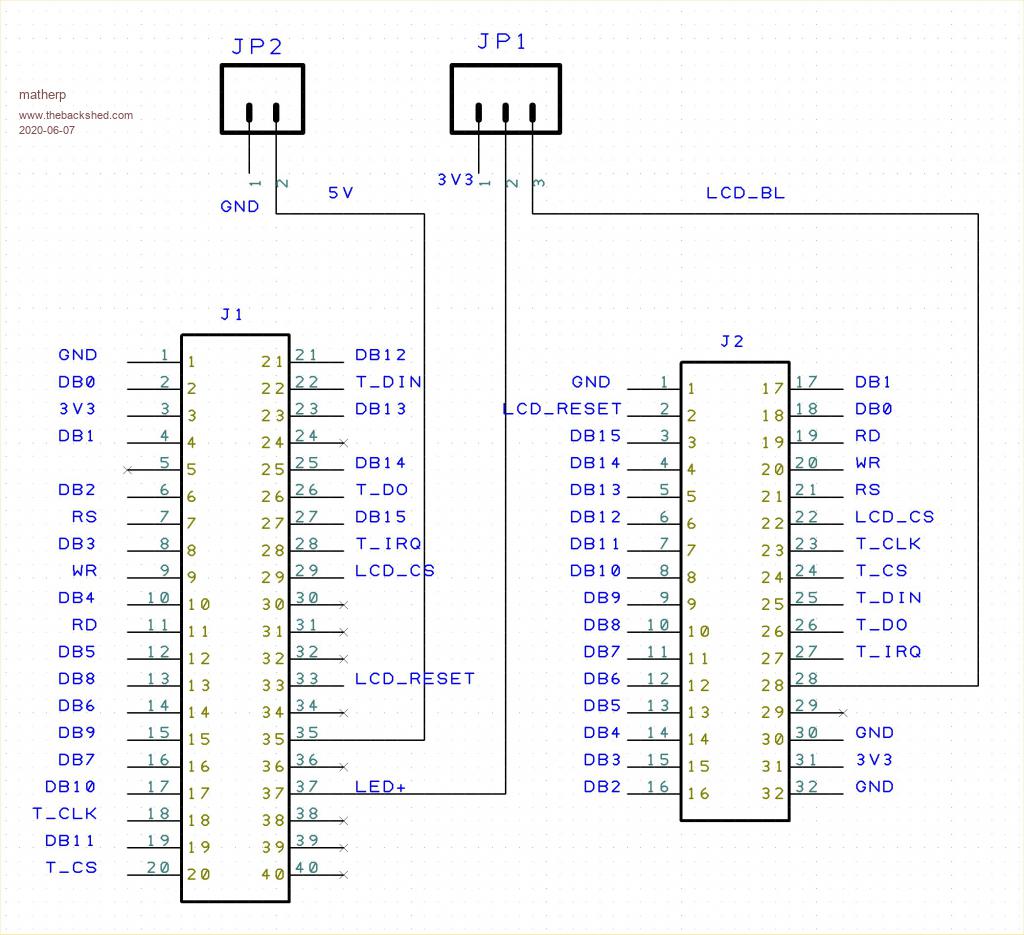 |
||||
| circuit Senior Member Joined: 10/01/2016 Location: United KingdomPosts: 226 |
I know that most of the focus has gone onto the CMM2, but a manual for this board would be welcomed enormously. I have piled through the fourteen pages of bulletin board and gleaned a lot of the minutiae, as well as trying to find the relevant information in the H7 manual and so forth but a consolidated manual for this great little board would be fantastic. This is a fabulously useful and very powerful little board and available at such a low price. Peter, I very much appreciate the work that you put into porting MMBASIC into this board - it is extremely versatile at such low cost; currently only �10 on Amazon. I can hardly believe that I can buy a board with a 32bit ARM processor, an SD card interface, a USB interface, a Winbond flash chip ...and a battery-backed real-time clock all for a tenner! Is there any hope of a consolidated manual anytime soon? ...please? |
||||
| JohnS Guru Joined: 18/11/2011 Location: United KingdomPosts: 3649 |
Sorry I can't help with your actual query but did you find the thread here? John |
||||
| Volhout Guru Joined: 05/03/2018 Location: NetherlandsPosts: 3496 |
To be honest, I would also like a comprehensive manual, not only for the F4 but for anything beyond the MM+. It is absolutely possible to find all information in what is written, but it is a bit distributed over documents. Few weeks ago I had to look something up on the MM extreme board, and could not find it in the MMextreme doc. Looked in the MM2 document, and finally found it in the MM+ documentation. Similar for the F4, information is distributed in 14 page threads, and an H7 manual that only lists what is added over the MM series. And part of the H7 manual is about features not in the F4, and the F4 has features not in the H7. If...Geoff and Peter would share the source files, I am offering to put in the sweat to combine the info for the F4 into ONE document. Few evenings of cut-and-paste should do it. My contribution to the forum....;) Volhout Edited 2020-07-15 05:18 by Volhout PicomiteVGA PETSCII ROBOTS |
||||
| matherp Guru Joined: 11/12/2012 Location: United KingdomPosts: 8569 |
Happy to share the source - send me a PM with your email address. However, just type LIST commands and LIST functions and that tells you what is there. Then by reference to the various threads you should be able to piece things together |
||||
| Decoy Senior Member Joined: 02/08/2019 Location: DenmarkPosts: 109 |
Hi guys I have several of these boards lying around - I was thinking, would it be possible to ever get something like a VGA or even composite output on them, and maybe a keyboard input? I really like the idea of a self-contained unit...like the MM :) Thanks! Nicholas |
||||
| Canada_Cold Newbie Joined: 11/01/2020 Location: CanadaPosts: 23 |
Hi Guys, I too have a couple of these boards, programmed with ARMmite MMBasic Version 5.05.09. I sure could use a list that showed the mapping of the pins on the board (by name PE0, PA2,,, etc) to the functions (COMx, I2Cx,,, etc) in MMBasic. Any help would be great. Don |
||||
| lizby Guru Joined: 17/05/2016 Location: United StatesPosts: 3010 |
This is what I made up for my use: 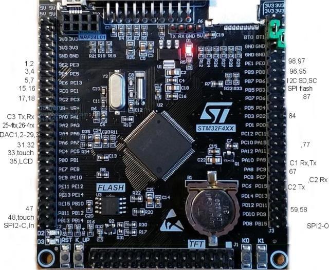 Also this from I'm not sure who: F4 Pin Functions.zip Edited 2020-07-16 22:34 by lizby PicoMite, Armmite F4, SensorKits, MMBasic Hardware, Games, etc. on fruitoftheshed |
||||
| Canada_Cold Newbie Joined: 11/01/2020 Location: CanadaPosts: 23 |
Hi lizby, That is Excellent, thank you so much. Don |
||||
| CaptainBoing Guru Joined: 07/09/2016 Location: United KingdomPosts: 1985 |
I am fairly certain the Arm versions of MMBasic can use the name of the pin as well as the number can you try Setpin PC13,DIN |
||||
| matherp Guru Joined: 11/12/2012 Location: United KingdomPosts: 8569 |
Here is the "official" mapping, and yes you can use the pin name whenever you need to specify a pin as the Captain says { NULL, 0, PUNUSED , NULL, 0}, // pin 0 { GPIOE, GPIO_PIN_2, DIGITAL_IN | DIGITAL_OUT , NULL, 0}, // pin 1 IR { GPIOE, GPIO_PIN_3, DIGITAL_IN | DIGITAL_OUT , NULL, 0}, // pin 2 Count 3/KEY1 { GPIOE, GPIO_PIN_4, DIGITAL_IN | DIGITAL_OUT , NULL, 0}, // pin 3 Count 4/KEY0 { GPIOE, GPIO_PIN_5, DIGITAL_IN | DIGITAL_OUT , NULL, 0}, // pin 4 PWM-3A { GPIOE, GPIO_PIN_6, DIGITAL_IN | DIGITAL_OUT , NULL, 0}, // pin 5 PWM-3B { NULL, 0, PUNUSED , NULL, 0}, // pin 6 VBAT { GPIOC, GPIO_PIN_13, DIGITAL_IN | DIGITAL_OUT, NULL, 0}, // pin 7 { NULL, 0, PUNUSED , NULL, 0}, // pin 8 OSC32_IN { NULL, 0, PUNUSED , NULL, 0}, // pin 9 OSC32_OUT { NULL, 0, PUNUSED , NULL, 0}, // pin 10 VSS { NULL, 0, PUNUSED , NULL, 0}, // pin 11 VDD { NULL, 0, PUNUSED , NULL, 0}, // pin 12 OSC8_IN { NULL, 0, PUNUSED , NULL, 0}, // pin 13 OSC8_OUT { NULL, 0, PUNUSED , NULL, 0}, // pin 14 NRST { GPIOC, GPIO_PIN_0, DIGITAL_IN | DIGITAL_OUT | ANALOG_IN , ADC1, ADC_CHANNEL_10}, // pin 15 { GPIOC, GPIO_PIN_1, DIGITAL_IN | DIGITAL_OUT | ANALOG_IN , ADC2, ADC_CHANNEL_11}, // pin 16 { GPIOC, GPIO_PIN_2, DIGITAL_IN | DIGITAL_OUT | ANALOG_IN , ADC3, ADC_CHANNEL_12}, // pin 17 { GPIOC, GPIO_PIN_3, DIGITAL_IN | DIGITAL_OUT | ANALOG_IN , ADC1, ADC_CHANNEL_13}, // pin 18 { NULL, 0, PUNUSED , NULL, 0}, // pin 19 VDD { NULL, 0, PUNUSED , NULL, 0}, // pin 20 VSSA { NULL, 0, PUNUSED , NULL, 0}, // pin 21 VREF+ { NULL, 0, PUNUSED , NULL, 0}, // pin 22 VDDA { GPIOA, GPIO_PIN_0, DIGITAL_IN | DIGITAL_OUT | ANALOG_IN , ADC1, ADC_CHANNEL_0}, // pin 23 COM3-TX/COUNT-0/WK_UP { GPIOA, GPIO_PIN_1, DIGITAL_IN | DIGITAL_OUT | ANALOG_IN , ADC1, ADC_CHANNEL_1}, // pin 24 COM3-RX { GPIOA, GPIO_PIN_2, DIGITAL_IN | DIGITAL_OUT | ANALOG_IN , ADC1, ADC_CHANNEL_2}, // pin 25 COM4-TX // { GPIOA, GPIO_PIN_3, DIGITAL_IN | DIGITAL_OUT | ANALOG_IN , ADC1, ADC_CHANNEL_3}, // pin 26 COM4-RX { NULL, 0, PUNUSED , NULL, 0}, // pin 27 VSS { NULL, 0, PUNUSED , NULL, 0}, // pin 28 VDD { NULL, 0, PUNUSED , NULL, 0}, // pin 29 DAC-1 { NULL, 0, PUNUSED , NULL, 0}, // pin 30 DAC-2 { GPIOA, GPIO_PIN_6, DIGITAL_IN | DIGITAL_OUT | ANALOG_IN , ADC1, ADC_CHANNEL_6}, // pin 31 PWM-1A +LED-D2 { GPIOA, GPIO_PIN_7, DIGITAL_IN | DIGITAL_OUT | ANALOG_IN , ADC1, ADC_CHANNEL_7}, // pin 32 PWM-1B +LED-D3 { GPIOC, GPIO_PIN_4, DIGITAL_IN | DIGITAL_OUT | ANALOG_IN , ADC2, ADC_CHANNEL_14}, // pin 33 { GPIOC, GPIO_PIN_5, DIGITAL_IN | DIGITAL_OUT | ANALOG_IN , ADC2, ADC_CHANNEL_15}, // pin 34 T_IRQ { GPIOB, GPIO_PIN_0, DIGITAL_IN | DIGITAL_OUT | ANALOG_IN , ADC1, ADC_CHANNEL_8}, // pin 35 PWM-1C/F_CS { NULL, 0, PUNUSED , NULL, 0}, // pin 36 LCD_BL { GPIOB, GPIO_PIN_2, DIGITAL_IN | DIGITAL_OUT , NULL, 0}, // pin 37 { NULL, 0, PUNUSED , NULL, 0}, // pin 38 FSMC_D4 { NULL, 0, PUNUSED , NULL, 0}, // pin 39 FSMC_D5 { NULL, 0, PUNUSED , NULL, 0}, // pin 40 FSMC_D6 { NULL, 0, PUNUSED , NULL, 0}, // pin 41 FSMC_D7 { NULL, 0, PUNUSED , NULL, 0}, // pin 42 FSMC_D8 { NULL, 0, PUNUSED , NULL, 0}, // pin 43 FSMC_D9 { NULL, 0, PUNUSED , NULL, 0}, // pin 44 FSMC_D10 { NULL, 0, PUNUSED , NULL, 0}, // pin 45 FSMC_D11 { NULL, 0, PUNUSED , NULL, 0}, // pin 46 FSMC_D12 { GPIOB, GPIO_PIN_10, DIGITAL_IN | DIGITAL_OUT , NULL, 0}, // pin 47 I2C2-SCL { GPIOB, GPIO_PIN_11, DIGITAL_IN | DIGITAL_OUT , NULL, 0}, // pin 48 I2C2-SDA { NULL, 0, PUNUSED , NULL, 0}, // pin 49 VCAP { NULL, 0, PUNUSED , NULL, 0}, // pin 50 VDD // { GPIOB, GPIO_PIN_12, DIGITAL_IN | DIGITAL_OUT , NULL, 0}, // pin 51 T_CS { GPIOB, GPIO_PIN_13, DIGITAL_IN | DIGITAL_OUT , NULL, 0}, // pin 52 SPI2-CLK { GPIOB, GPIO_PIN_14, DIGITAL_IN | DIGITAL_OUT , NULL, 0}, // pin 53 SPI2-IN { GPIOB, GPIO_PIN_15, DIGITAL_IN | DIGITAL_OUT , NULL, 0}, // pin 54 SPI2-OUT { NULL, 0, PUNUSED , NULL, 0}, // pin 55 FSMC_D13 { NULL, 0, PUNUSED , NULL, 0}, // pin 56 FSMC_D14 { NULL, 0, PUNUSED , NULL, 0}, // pin 57 FSMC_D15 { GPIOD, GPIO_PIN_11, DIGITAL_IN | DIGITAL_OUT , NULL, 0}, // pin 58 Drive_VBUS_FS { GPIOD, GPIO_PIN_12, DIGITAL_IN | DIGITAL_OUT , NULL, 0}, // pin 59 PWM-2A { NULL, 0, PUNUSED , NULL, 0}, // pin 60 FSMC_A18 { NULL, 0, PUNUSED , NULL, 0}, // pin 61 FSMC_D0 { NULL, 0, PUNUSED , NULL, 0}, // pin 62 FSMC_D1 { GPIOC, GPIO_PIN_6, DIGITAL_IN | DIGITAL_OUT, NULL, 0}, // pin 63 COM2-TX { GPIOC, GPIO_PIN_7, DIGITAL_IN | DIGITAL_OUT, NULL, 0}, // pin 64 COM2-RX { NULL, 0, PUNUSED , NULL, 0}, // pin 65 SDIO_D0 { NULL, 0, PUNUSED , NULL, 0}, // pin 66 SDIO_D1 { GPIOA, GPIO_PIN_8, DIGITAL_IN | DIGITAL_OUT , NULL, 0}, // pin 67 { GPIOA, GPIO_PIN_9, DIGITAL_IN | DIGITAL_OUT , NULL, 0}, // pin 68 COM1-TX { GPIOA, GPIO_PIN_10, DIGITAL_IN | DIGITAL_OUT , NULL, 0}, // pin 69 COM1-RX // { NULL, 0, PUNUSED , NULL, 0}, // pin 68 CONSOLE-TX // { NULL, 0, PUNUSED , NULL, 0}, // pin 69 CONSOLE-RX { NULL, 0, PUNUSED , NULL, 0}, // pin 70 USB-DM { NULL, 0, PUNUSED , NULL, 0}, // pin 71 USB-DP { GPIOA, GPIO_PIN_13, DIGITAL_IN | DIGITAL_OUT , NULL, 0}, // pin 72 SWDIO { NULL, 0, PUNUSED , NULL, 0}, // pin 73 VCAP { NULL, 0, PUNUSED , NULL, 0}, // pin 74 VSS { NULL, 0, PUNUSED , NULL, 0}, // pin 75 VDD // { GPIOA, GPIO_PIN_14, DIGITAL_IN | DIGITAL_OUT , NULL, 0}, // pin 76 SWCLK { GPIOA, GPIO_PIN_15, DIGITAL_IN | DIGITAL_OUT , NULL, 0}, // pin 77 KBD_CLK { NULL, 0, PUNUSED , NULL, 0}, // pin 78 SDIO_D2 { NULL, 0, PUNUSED , NULL, 0}, // pin 79 SDIO_D3 { NULL, 0, PUNUSED , NULL, 0}, // pin 80 SDIO_CK { NULL, 0, PUNUSED , NULL, 0}, // pin 81 FSMC_D2 { NULL, 0, PUNUSED , NULL, 0}, // pin 82 FSMC_D3 { NULL, 0, PUNUSED , NULL, 0}, // pin 83 SDIO_CMD { GPIOD, GPIO_PIN_3, DIGITAL_IN | DIGITAL_OUT , NULL, 0}, // pin 84 KBD_DATA { NULL, 0, PUNUSED , NULL, 0}, // pin 85 FSMC_NOE { NULL, 0, PUNUSED , NULL, 0}, // pin 86 FSMC_NWE { GPIOD, GPIO_PIN_6, DIGITAL_IN | DIGITAL_OUT , NULL, 0}, // pin 87 { NULL, 0, PUNUSED , NULL, 0}, // pin 88 FSMC_NE1 { GPIOB, GPIO_PIN_3, DIGITAL_IN | DIGITAL_OUT , NULL, 0}, // pin 89 SPI_CLK { GPIOB, GPIO_PIN_4, DIGITAL_IN | DIGITAL_OUT , NULL, 0}, // pin 90 SPI_IN { GPIOB, GPIO_PIN_5, DIGITAL_IN | DIGITAL_OUT , NULL, 0}, // pin 91 SPI-OUT { GPIOB, GPIO_PIN_6, DIGITAL_IN | DIGITAL_OUT , NULL, 0}, // pin 92 I2C-SCL/NRF_CE { GPIOB, GPIO_PIN_7, DIGITAL_IN | DIGITAL_OUT , NULL, 0}, // pin 93 I2C-SDA/NRF_CS { NULL, 0, PUNUSED , NULL, 0}, // pin 94 BOOT0 { GPIOB, GPIO_PIN_8, DIGITAL_IN | DIGITAL_OUT , NULL, 0}, // pin 95 PWM-2B { GPIOB, GPIO_PIN_9, DIGITAL_IN | DIGITAL_OUT , NULL, 0}, // pin 96 PWM-2C { GPIOE, GPIO_PIN_0, DIGITAL_IN | DIGITAL_OUT , NULL, 0}, // pin 97 { GPIOE, GPIO_PIN_1, DIGITAL_IN | DIGITAL_OUT , NULL, 0}, // pin 98 COUNT 1 { NULL, 0, PUNUSED , NULL, 0}, // pin 99 VSS { NULL, 0, PUNUSED , NULL, 0}, // pin 100 VDD |
||||
| Canada_Cold Newbie Joined: 11/01/2020 Location: CanadaPosts: 23 |
Thanks, Don |
||||
| RonnS Senior Member Joined: 16/07/2015 Location: GermanyPosts: 120 |
hello, i want to know which pins are 5volt tolerant i want to count pulses from a brushless motor driver thanks |
||||
| matherp Guru Joined: 11/12/2012 Location: United KingdomPosts: 8569 |
Try the datasheet for the chip |
||||
| Spoth Newbie Joined: 11/01/2021 Location: FrancePosts: 2 |
Hello, Is it possible to have the source code for ArmmiteF4. I'd like to adapt to this board https://www.aliexpress.com/item/4000602517153.html?spm=a2g0s.9042311.0.0.1ec64c4d70rbZZ and I think it will only be a small amount of work to adapt only for the pins. Thanks |
||||
| matherp Guru Joined: 11/12/2012 Location: United KingdomPosts: 8569 |
I've passed the source to Geoff to make available through MMBASIC.COM when he has a chance. You must understand the licencing conditions through - it is for your own use only and firmware generated from the source may not be distributed. There is also no support for source or how to compile/build it. |
||||
| Spoth Newbie Joined: 11/01/2021 Location: FrancePosts: 2 |
Thanks for the answer. I got the source code from MMBASIC.COM but only for STM32H7. I'll have a closer look |
||||
| matherp Guru Joined: 11/12/2012 Location: United KingdomPosts: 8569 |
I've just sent him the F4 source - but you will need to wait for him to have a chance to post it UPDATE Now posted - thanks Geoff Edited 2021-01-12 22:58 by matherp |
||||
