
|
|
Forum Index : Windmills : visual effect of capacitors
| Page 1 of 25 |
|||||
| Author | Message | ||||
| GWatPE Senior Member Joined: 01/09/2006 Location: AustraliaPosts: 2127 |
Hi readers, PS edit:3/12/08 An important consideration that should be noted, is that the capacitor coupling arrangements are charge pumps, and as such, these should not be left unloaded. An unloaded system, even if the mill is only producing a few ACvolts, has the potential to still produce hundreds of DC volts on the output over time. Due care should still be taken and treat all connections as lethal. I have helped Dennis with some recording of CRO outputs of an 80SP in star configuration at 350rpm. I have arranged the pics as comparisons. 200uF was placed between each set of windings. readings were taken unloaded and supplying a 24V battery at a constant voltage. All vertical scales are 10V/div. this pic is the unloaded output waveform without and then with capacitors before the rectifier from the star point as reference. 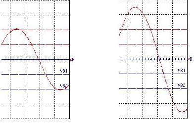
this pic is the loaded output waveform without and with capacitors before the rectifier from the star point as a reference. 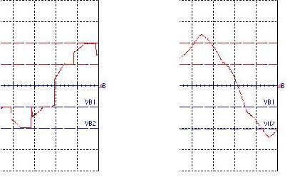
this pic is the loaded output that the battery sees. This is between bat -ve and the winding. this is across the bridge rectifier. 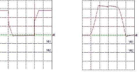
The results show clearly the voltage gain. The loaded current at 350rpm increased from 3A to 11A with capacitors. The capacitors do significantly reduce the cutin speed. This will allow a particular windmill with a high cutin to produce current at approx 2/3 the rpm. cheers, Gordon. become more energy aware |
||||
oztules Guru Joined: 26/07/2007 Location: AustraliaPosts: 1686 |
Gordon, Nice to see some clarification of what happens. The best feature of this it to allow larger blades to take advantage of lower winds. I guess that changing the capacitors values will allow fine tuning to get out of stall much like a resistor does,... but without the loss. This perhaps should attract more positive attention than has been attributed thus far. It may allow others to avoid the gearing thing,if the prop size allows for a 2/3 compromise to achieve close to the same thing. The non-linear response of the diode has been cleaned up quite a bit, this may help those who wish to track rpm via frequency. Usually diodes under load make so much hash, that filtering is very important/tricky. The input line looks clean enough to read with a normal digital volt meter. (freq range)... handy. Usually, once cut in is achieved, the meter goes haywire. (no filter). All in all, thanks to you and Dennis for these results. ..........oztules Village idiot...or... just another hack out of his depth |
||||
| KiwiJohn Guru Joined: 01/12/2005 Location: New ZealandPosts: 691 |
Gordon, when you say the current increased from 3A to 11A at what point in the circuit are you measuring this? |
||||
Gill Senior Member Joined: 11/11/2006 Location: AustraliaPosts: 669 |
Gordon, Certainly it implies an advance yet "The loaded current at 350rpm increased from 3A to 11A with capacitors" is of no benifit if the power drawn from the motor is 4 times as much at that rpm.... As commented with Brucedownunder's test bed, power OUT has no valid reference for comparison without an accurate power IN comparison. Without that data I can only say the wave form is pretty, but does pretty charge batteries better? was working fine... til the smoke got out. Cheers Gill _Cairns, FNQ |
||||
| GWatPE Senior Member Joined: 01/09/2006 Location: AustraliaPosts: 2127 |
Hi Gill & KiwiJohn, I think you will realize that I have in the past been critical about the effects of capacitors and windmill loading also. The currents stated above were battery load currents. This means that at the 350rpm level, a F&P 80SP stator, is only just above cutin to produce the 3A. The capacitors allow the mill to produce a higher voltage and hence at the same 350rpm, more current, 11A, can be produced. I have not mentioned anything re efficiencies. I have merely pointed out that capacitors can be used to better match the windmill output to the load. In this example, the same stator would cutin at a lower rpm with the capacitors. It is obvious that if this was a real windmill and not a test bench that more power would need to be extracted from the wind and this would result in a slower rpm and hence the current gained may not be as much as the test bed at constant rpm. This purely highlights a way of producing power from a lower rpm, without the need of rewiring. .. Gordon. become more energy aware |
||||
| KiwiJohn Guru Joined: 01/12/2005 Location: New ZealandPosts: 691 |
Looks good Gordon! I dont have any problem with capacitors as I fully recognise the need to match source to load. |
||||
| oztules Guru Joined: 26/07/2007 Location: AustraliaPosts: 1686 |
Gill, Perhaps we need to stand back and see what we have done here. If we currently have a well matched system (blade diam and tsr to alternator), capacitors will have no benefit at all, and will only serve to stall the blades so that they cannot work at all.... so where to next? If we wish to take advantage of low winds (as an example), we could carve out some 4m blades, with a tsr of around 5. This is easy to carve to get this tsr, and will be quiet as well. If we did this, to get our 350rpm, we would need a 34 mph wind to get 3A out of the stator Gordon and Dennis were testing(@24v) ie 75watts. We would have available some 7000watts to play with at the shaft, so efficiency is not the problem.... cut in speed is. Now we add the capacitors, now at 34mph, 350 rpm, we are getting 11A @24v . So we have gained some advantage. The capacitors were giving the "system" a marked gain. We still have 7000 watts available so power is a non-issue. Now it is clear that this example is both unlikely and silly in the component match, but it gives an indication of how the cap loading effects performance. In less extreme cases say 3m prop tsr 5, we get our 350 rpm @22mph. Without caps, we get 3A@24v (about 75watts), or with caps we get 11A@24v or approx 260watts. Now shaft power is about 1300 watts, so there is plenty to spare. In this system you need either gearing to speed the mill up (messy and lossy), increase the tsr considerably (harder and noisier), add caps, or some workable form of mppt (or Maximiser). In this instance the caps are the best practical course of action. We have 5 times the power available to use if we can, so efficiency is of no consequence. We have power to burn, just difficulty in getting the revs to use the stator effectively (matching it). Thats where this capacitor system has some serious advantages to "no caps, higher rpm, smaller blades (to achieve those higher rpm), lower low wind performance (because we need smaller blades to get cutin)". But, we can't use it to improve a matched system, because your concerns now take precedence. (where is the extra power coming from). So I guess it is like everything else in the world, different horses for courses. In some cases it will be a clear winner, in others, will be burdensome. One other advantage which seems to be available, is that the cleaner waveform should improve power factor some, and reduce circulating currents in the alternator, as the harmonics from rectification are reduced significantly. I am blindly guessing that with the improved wave form, efficiency will be better than original anyway into a rectifier/battery scenario (and it could be bollocks too... your "power in /power out" testing is required here) Just my take on it, it has a place in the scheme of things I feel, particularly if you want more power from low winds by increasing blade diam, but without rewinding/rewiring the stator. ..........oztules Village idiot...or... just another hack out of his depth |
||||
| Gill Senior Member Joined: 11/11/2006 Location: AustraliaPosts: 669 |
Gordon, otules, The application is not jumping out at me right now. I'll give it more thought later. Certainly noting and applying such characteristics to our advantage is how things are improved. was working fine... til the smoke got out. Cheers Gill _Cairns, FNQ |
||||
| GWatPE Senior Member Joined: 01/09/2006 Location: AustraliaPosts: 2127 |
Hi Gill, If you already have obtained a match between the blades, the generator and the load, then adding capacitors may reduce output. I suspect this may be the case for hydro, or a vegy diesel, but I doubt this would be the case for a windmill. If you already had achieved maximum power across a wide wind power range, you would not need to build an electronic MPPT. .. .. Gordon. become more energy aware |
||||
| GWatPE Senior Member Joined: 01/09/2006 Location: AustraliaPosts: 2127 |
Hi all, I am not sure how may windmill owners have tested the effects of capacitors on a mill in the wind. I know that Bryan has had success and Bushboy Bruce has not. I have just tried 110uF and 220uF on my 100S in star. Power output dropped and more significantly mill rotor speed ran away at higher windspeeds. Power output increased with windspeed up to 5A output and then decreased to 0 with further increasing windspeed for both capacitors values tested. I was wondering if anyone has recorded this problem as well. I will test my machine in delta with caps when it stops raining to see if Bryans results can be replicated. Gordon. become more energy aware |
||||
| Gizmo Admin Group Joined: 05/06/2004 Location: AustraliaPosts: 5012 |
Thats interresting Gordon. It's as though something was throwing the tuning out as the windmill RPM increased. Like some sort of canceling of the resonance, sort of thing, you know what I mean. I wonder if the cap location is important, like connected across the F&P terminals or further away at the bottom of the tower. Could it be something down the line from the rectifiers, like a different battery internal resistance to those used in the earlier tests. Glenn The best time to plant a tree was twenty years ago, the second best time is right now. JAQ |
||||
| GWatPE Senior Member Joined: 01/09/2006 Location: AustraliaPosts: 2127 |
Hi Gizmo, This has been only a prelim investigation. This is the only way possible to do realistic testing on a mill in operation, ie add caps to mill at bottom of the tower before rectification. There is probably an LwC interaction. An engineer may have an explanation. The LC combination appears to prevent current flow above a certain frequency. The current returned to the battery load increased and then decreased as the mill slowed down. Very strange to see the currrent increase as the rpm decreased. When the caps were removed at the high rpm, the mill loaded normally to the full amps, so the load was not a problem. The emf diminished above a certain rpm. The cap effectively loaded the coil to a point that the output emf was below the battery voltage. I cannot explain why the mill rpm increased. maybe the current developed an emf in the wiring and this effectively unloaded the mill, like placing resistance in the line. I want to test this stator in delta again with caps. I am sure the pole twisting has changed the output waveform from a pure sine wave. This will probably mean independent rectification of each phase and a cap across the winding, effectively across the rectifier. This will have to be on the mill head. Luckily there is plenty of room inside the yaw box. I will not be able to use the chinese mill controller to do this. I will have to use a normal diversion load controller as mill and battery protection. I have a heap of 470uF 180WV electro caps that I will back to back configure to be non polarised, approx 235uF. I will make some quick connects with flex to the stator. Solder or blue point connections will have to wait. I have zero loss type connects that will save me a heap of time doing mods with the mill lowered. I was unable to do much today. Rain, and strong winds not much fun with live windmill testing. High pressure system will kill the wind for a while, so OK to leave as is for a while. I am still in 2 minds re caps. I will need to talk to Dennis about a series 80 to rewire, to allow me to direct compare previous testing he has done. I have seen an increase in power with caps. The test rig had much shorter wiring runs. It may be that the wiring and component placement may be critical aspects of a successful use of capacitors on a windmill. This is likely the tip of an iceburg, so I will press on. Gordon. become more energy aware |
||||
Haxby Guru Joined: 07/07/2008 Location: AustraliaPosts: 418 |
I have not seen high value non-polarised caps on the market before. What caps are you using? Most caps I have seen have a ripple rating. If you reverse their polarity as you are doing, I believe they will fail very quickly. Also, the faster the mill goes, the more the capacitor conducts (short circuits the winding) due to the higher charge/discharge frequency, and higher mill frequency. |
||||
| GWatPE Senior Member Joined: 01/09/2006 Location: AustraliaPosts: 2127 |
Hi haxby, this has been discussed elsewhere on another thread. I believe oztules was a contributor. The caps are back to back 470uF@180WV giving an effective 230uF non polarised equivalent. These are 25mm x 35mm cans, with high ripple rating. I checked for heating, none! Use at least a x5 system voltage rating on the caps. Good luck with your testing. Gordon. become more energy aware |
||||
| KiwiJohn Guru Joined: 01/12/2005 Location: New ZealandPosts: 691 |
I think it should be recognised that the introduciton of capacitors is a form of 'tuning' and that the effects will not be the same under all conditions. If my meagre understanding is at all correct adding capacitors will give a peak improvement around a particular RPM and might even give a decrease in output at other speeds. |
||||
| GWatPE Senior Member Joined: 01/09/2006 Location: AustraliaPosts: 2127 |
Hi kiwijohn, You have hit the nail on the head. There may be only one useful reigime where capacitors make an improvement. I intend to try and replicate bench testing results on a mill. A windmill flying has much more driving potential to a bench test. In the test conditions I explored, the wind energy was many kW at the top end of the power range. This would probably be hard to replicate on a test rig. I suspect that bryan has a possible lucky streak. He should try and measure some other components, ie windspeed and rpm, degree of furling etc, at the same time. A comparison without caps in similar conditions would be useful. The parallel arrangement of capacitors with the output windings should be a low pass filter. the capacitor should present an increasing load as the frequency increases. This is what I found in my testing. The loading increased with frequency until the rectified output voltage was less than the battery voltage. Placement in the wiring may be critical. The placement of the capacitors in my test was probably wrong. More testing will clarify things. Gordon. become more energy aware |
||||
| KiwiJohn Guru Joined: 01/12/2005 Location: New ZealandPosts: 691 |
Gordon, I doubt there is a truer statement than yours when you say placement of the capacitors in the circuit may be critical! 
There are two aspects, I think, where capacitors could bring improvement. One is where the addition of capacitance brings the current phase into exact synchronisation with the voltage phase as presented to the rectifiers. I say this because if I understand correctly the diodes are actually not conducting between the point where the voltage is -0.6V and until it rises about +0.6V. Now this would not be much of an issue if there was no current flowing during that time but as in an inductive circuit current lags voltage I assume current is abruptly cut off when the diodes stop conducting and current is slow to get going again when the diodes turn on again. Presumably this is what causes the strange step shapes we see in the various current waveforms that have been posted. Now the second aspect, which I fully admit may actually be the same, is that the current through the inductive coils will be slow to rise in reaction to the changing magnetic flux and I presume if there was capacitance to counter this inductive reactance the current would rise faster. The watts we can get out of the alternator is the multiple of amps times volts and because this is alternating current we also have a 'power factor'. Power factor is always less than one except when current is in phase with voltage. Presumably when we have a power factor of less than one we need more current to get the same watts and more current means more resitance (i.e. heat) losses. Now, and I apologise for being so long winded, it appears what we really need to get from the addition of capacitors is a power factor of one in the AC part of our system. I think someone with just a little more knowledge than me could find the inductance of the various coil configurations and could calculate the ideal size capacitors for a particular RPM. |
||||
| Haxby Guru Joined: 07/07/2008 Location: AustraliaPosts: 418 |
The issue of power factor is an important one to consider when you are doing your measurements. If the power factor is badly out, and the batteries and cable hook up has some inductance, then you might be measuring many amps at the zero crossing of the sine wave. You might then be tricked into thinking the batteries are charging because you simply multiply amps x volts that you see on your bench meter, but in actual fact because the amps are trailing the volts, you are getting less power than you think. A dual input scope will show the **instantaneous** relationship between amps and volts and will give an insight into the true power produced. |
||||
| Haxby Guru Joined: 07/07/2008 Location: AustraliaPosts: 418 |
Or if you dont have a dual input scope, at least run the output through a large parallel capacitor before the batteries, and measure between this cap and the batteries. Also, has anyone used caps back to back for a long period of time successfully? The higher the capacitance the lower the frequency required before the capacitor starts to act like a wire link in the system. While the cap might not be getting hot, it is shorting out all the lines to the mill (at a point on the sine wave). The better the ESR (equivalent series resistance) of the cap the better it will handle the shorts, but I don't believe caps were designed for this type of torture. |
||||
| KiwiJohn Guru Joined: 01/12/2005 Location: New ZealandPosts: 691 |
Um...... shouldnt there be DC on the battery side of the rectifiers? We could put capacitors on the DC side of the rectifiers to smooth out the ripple but I dont think that would do much for the power factor on the AC side of the rectifier would it? |
||||
| Page 1 of 25 |
|||||
