
|
|
Forum Index : Windmills : visual effect of capacitors
| Author | Message | ||||
Downwind Guru Joined: 09/09/2009 Location: AustraliaPosts: 2333 |
Hi Niall, I fail to see how that can work?? You also imply a 6 phase input from what i can make of it. Pete. Sometimes it just works |
||||
| VK4AYQ Guru Joined: 02/12/2009 Location: AustraliaPosts: 2539 |
I'm dumb to this. I wait in expectation Bob Foolin Around |
||||
niall1 Senior Member Joined: 20/11/2008 Location: IrelandPosts: 331 |
i,m not fully sure about the diagram...i,m trying to rembember it but probabely getting it wrong....nothing new there then.... its something to do with adding dc voltages through capacitors  .. ..
the input is three phase Pete , each start and end are brought out and rectified independently then the dc voltages are linked (added ?) through the caps , i think some people used it on fieldlines with car alts to get higher voltage from an existing stator without doing a rewind .... the way i look at is , its kind off like charging three small batteries in series then taking the sum of all three as an output .....maybe i,m just losing it... 
i rembember playing around with it a long time ago and think it did work in some form i try to find that old link....that should help niall |
||||
| niall1 Senior Member Joined: 20/11/2008 Location: IrelandPosts: 331 |
bugger...i knew i was raving...sorry about the failed auto cad experiment Bob pic from wooferhound on fieldlines and a link 
http://fieldlines.com/board/index.php/topic,143290.0.html edit...this topic came up much further back as well but its tricky to find it looking at the circuit now ....it doesent look like a conventional cap doubler circuit...the boost is on the dc side...??..  niall |
||||
| turnymf Regular Member Joined: 04/10/2008 Location: AustraliaPosts: 84 |
I found this animation usefull for getting my head around 3 phase http://www.youtube.com/watch?v=gm7d1lwPPno This is a huge thread, any chance of an abridged version? cheers |
||||
| GWatPE Senior Member Joined: 01/09/2006 Location: AustraliaPosts: 2127 |
Testing of my windmills with caps is continuing. Current setup can change windmill behaviour from underloaded of optimum to overloaded of optimum with a switch click. caps do reduce the maximum rpm my windmills attain during a wind gust, with a smoothing of the output power. The windmill is no where near as lively. The broader range of power output make the windmill more productive most of the time. The few hundred watts lost from the peak power, during the peak of a wind gust, is made up in spades by the windmill producing power at half the rpm the rest of the time. I don't have time at present to present any data. The analyzer program I am making is a multi dimensional array and writing the program to get all components to work together is taking plenty of time. Would be good if other readers could submit some comparison data from there own windmills to have a look at. Gordon. become more energy aware |
||||
| VK4AYQ Guru Joined: 02/12/2009 Location: AustraliaPosts: 2539 |
Hi Gordon I tried a 3 cap on my Chinese mill with 3 caps connected to the three phase points {+} and the three {-} joined in a star formation and it brought the volts up 5 volts on the output rectifier is this what you had in mind? All the best Bob Foolin Around |
||||
Steve9R Regular Member Joined: 24/01/2006 Location: AustraliaPosts: 72 |
Are we ever going to see this mystic 3 cap method or are we just wasting our time ?? |
||||
| Downwind Guru Joined: 09/09/2009 Location: AustraliaPosts: 2333 |
I think Gordon has been waiting for some good winds to be able to test and see the full results of the new cap mods, before posting what could be considered a waste of time without proof of it all working effecently. It takes time to be able test things. Be patient and wait for the results. No information is better than bad information. Pete. Sometimes it just works |
||||
AMACK Senior Member Joined: 31/05/2009 Location: AustraliaPosts: 184 |
Gordon, I have sent you a PM for some advise on caps. I could not send a photo so I thought I might as well post it here so all can see. I still have trubble getting my head around the cap doubler but here goes. I have 36 X 330 uf 250volt caps 2 X 50 amp recs and 1 X 100 amp rec and the recs are three phase. I heed some help to work out the wiring as I have not worked with 3 phase recs before. From what I can gather I was going to run the 100 amp as the main from the Gen and use the 50 amps with the caps. There is some wiring on the caps and I have posted a photo. As you can see the caps are in groups of 12. 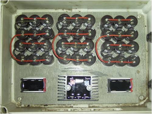
AMACK *Note to self 1. Make it thick 2.Make it heavy. 3.Make it stronger than it should be. 4. Don't rush the first job as the second job will cost more and take mor |
||||
fillm Guru Joined: 10/02/2007 Location: AustraliaPosts: 730 |
Hi Amack , If you lay out your bridge recs like this the wiring flows a bit better 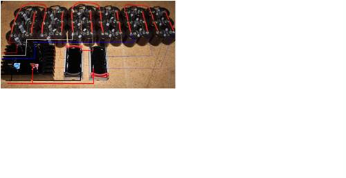
I will send it to you by email as well as it might be a bit small and you can use zoom to enlarge it PhillM ...Oz Wind Engineering..Wind Turbine Kits 500W - 5000W ~ F&P Dual Kits ~ GOE222Blades- Voltage Control Parts ------- Tower kits |
||||
| GWatPE Senior Member Joined: 01/09/2006 Location: AustraliaPosts: 2127 |
Hi Bryan, I took this extract of yours from one of the other threads, and think this part belongs here. I think that if you read through this "visual effect of capacitors" thread that you will see that I have credited yourself and Dennis for original testing of caps, in parallel and a series aspect on a F&P windmill alternator. I continued my own testing, firstly with a F&P windmill and later with an AxFx windmill. fillm has also assisted with component testing. Early "Real life" testing was done on my own windmills. I had found that in certain conditions my own windmill using parallel caps caused premature windmill runaway. Series caps alone on a windmill were a significant component and the sizing was proportional to the windmill power. This was a major drawback and some comments were made along the lines of truckloads of caps would be needed. I continued along another tack and started exploring capacitor diode combinations, now lumped together simply as cap voltage doublers. These arrangements resulted in smaller components and lower power requirements needed by the capacitors and diodes. I will take credit for finding the benefits a 3phase parallel/series cap doubler has to the load matching properties that are offered to a windmill that was wound for high cut in and power optimized for top end wind performance into a battery. The windmill would of course normally miss significant power harvest in low wind conditions. I will remember the path that has resulted. I think that sometimes people who played a part in a process may be lost in time. If I was continuing with just series caps, then I am sure that I would not be entitled to take any credit, but I feel that any credit I am now given to the cap arrangements that are now presented in an article on this site is justified. I was reluctant to add any more to this monumental thread. I have been unable to get any meaningful data from testing of other ideas I had. I am finalizing my testing now and summing up that the arrangement in the cap article will stand. Gordon. become more energy aware |
||||
| turnymf Regular Member Joined: 04/10/2008 Location: AustraliaPosts: 84 |
Hi Gordon Are you referring to the cap arrangement on page 15? Cheers for that btw I have constructed that diagram using electric fence caps and was impressed with the results 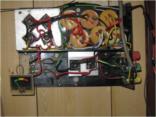
The caps are 30uf at around 900v The meter is looking at the cap arrangement current I tried several configs on a small hand powered jig as I am vawt so low rpm Once I get a few more caps I'll go back to testing again Once I screwed this to the wall and hooked it up the wind instantly stopped cheers |
||||
| GWatPE Senior Member Joined: 01/09/2006 Location: AustraliaPosts: 2127 |
Hi readers, I have had the opportunity to test my 48V wound stator on a 24V battery system. The rotor was stalled heavily by the alternator with this loading. I was able to get the mill working well with 3300uF of back to back series caps in each phase lead. There is a down side in that the caps do not load adequately at higher power levels, and it is necessary to have windmill rpm/output voltage sensing, to activate a diversion loading, to prevent windmill overspeeding. It looks like the best arrangement is the voltage doubler to load the windmill at low rpm, rather than to unload a windmill that has stalled behaviour. Gordon. PS: will be making a new stator with half the turns, as this will allow the direct 24V connection with a cap doubler to pick up low wind power. It is still best to get the turns close to right for the system voltage and optimum rotor rpm for cutin. become more energy aware |
||||
| GWatPE Senior Member Joined: 01/09/2006 Location: AustraliaPosts: 2127 |
Hi readers, The stator mentioned above was originally 215 turns per phase, with 75 turns per coil. I could not get it to work aceptably on 24V. I opted to rewire, rather than make a new stator. This stator had appreciable hum when producing power. I separated one coil from each phase and rewired the remaining coils in star. The separated coils were reconnected to the interconnection points of the 2 coils on each phase, to make a parallel set of coils. I kept the star points separate. The output connections were just to the ends of each phase wire from the 2 series coils. I connected a cap doubler and main rectifiers to the system. The performance is per this link The dot curve that follows the green line is with the cap doubler, compared to the more straight dot curve that is without the cap doubler. As it turns out, the windmill is now almost silent, and the output follows the wind energy. There is a dull hum only, but nothing like it was. The caps have changed the loading significantly, and have allowed current to flow through the windings for a longer percentage of the time, even though still connected to the battery. The clipping of the AC waveform that normally occurs with rectifiers and a battery is softened by the effects of the AC coupled caps. The rewire is not a traditional arrangement, as I wanted to use as much of the original copper as possible. The output is still appears very sinisoidal, and there is no drag when spun unloaded. The winding was tested in delta originally for 24V operation, and there was considerable drag when spun unloaded, indicating circulating currents in delta. Individual phase rectification was considered and rejected as it would have required rectifiers on the mill. It turns out that the cap doubler and a rewire has allowed me to reuse this stator, and I will not need to make a new one. Gordon. PS: the caps were 4700uF and 35V, low ESR. At full power, approx 1000W windmill, and 4-5A through the doubler, the SMD rectifiers rose approx 20deg above ambient, and the caps rose 18deg. If I had 3300uF @ 63V, low ESR, these would have worked as well. become more energy aware |
||||
| turnymf Regular Member Joined: 04/10/2008 Location: AustraliaPosts: 84 |
thanks for the update Gordon How long was the doubler running for the temp increase? cheers |
||||
| VK4AYQ Guru Joined: 02/12/2009 Location: AustraliaPosts: 2539 |
Hi Gordon It tracks the power curve very well with that arrangement, I notice that it has a few dots in the high side of the curve, is this the doubler or the combination with the through rectifier.? How will it perform further up the power curve with the winding reconfiguration, also could you do a mud map of your coil configuration so I can get my head around it. Also your delta connection as tried,as I think there was an impedance loop between unequal coil turns causing the internal loading. All the best Bob Foolin Around |
||||
| Xmaswiz Regular Member Joined: 14/04/2011 Location: United StatesPosts: 69 |
Hi all, have what might be a stupid question; can motor caps be used in place of electrolytic? I can find relatively cheap ones, or is the farad rating too high on those? thanks Noel Santa Maria, CA. Noel |
||||
| fillm Guru Joined: 10/02/2007 Location: AustraliaPosts: 730 |
Noel, AC motor start caps can be used as they are not polarised, so you need half the amount for a doubler . I think you will find their uF to small and will need to series quite a few to get meaningfull results . I have found a min of 300 to 600uF is a good start. PhillM ...Oz Wind Engineering..Wind Turbine Kits 500W - 5000W ~ F&P Dual Kits ~ GOE222Blades- Voltage Control Parts ------- Tower kits |
||||
| Xmaswiz Regular Member Joined: 14/04/2011 Location: United StatesPosts: 69 |
Hi, I found these 110-125 Volt Start Capacitor - 1290-1548 Mfd from www.globalindustrial.com, and for the cost they are slightly cheaper than using 2 DC caps of roughly the same values. Do you think these would be a suitable? (I am including the cost of shipping with the total number of caps for comparison). thanks  Santa Maria, CA. Noel |
||||
