
|
|
Forum Index : Electronics : Nano Power Inverter - Roll Your Own Style
| Author | Message | ||||
| Warpspeed Guru Joined: 09/08/2007 Location: AustraliaPosts: 4406 |
Yup, that is pretty much what I was seeing. In my case the required dc was +15v, and under no load conditions would reach about +20v. I just added a 16v zener, and problem solved. I would probably still be doing it that way if those little Chinese two dollar postage stamp power supplies had not become available. Cheers, �Tony. |
||||
| BenandAmber Guru Joined: 16/02/2019 Location: United StatesPosts: 961 |
Hey warp speed if you get a chance could you put a link to the little postage stamp size power supply that you used I would like to buy 5 or 10 of them just to have around I've been Gathering up stuff for future projects And another question do you use these kind of power supplies in your warp speed inverter be warned i am good parrot but Dumber than a box of rocks |
||||
renewableMark Guru Joined: 09/12/2017 Location: AustraliaPosts: 1678 |
If 65A will do these ar a lot cheaper Cheers Caveman Mark Off grid eastern Melb |
||||
| Warpspeed Guru Joined: 09/08/2007 Location: AustraliaPosts: 4406 |
These are the supplies Ben: https://www.ebay.com.au/itm/New-AC-DC-Power-Supply-Buck-Converter-Step-Down-Module-5V-12V-3-3V-9V-24V-500mA/262807265342 ?ssPageName=STRK%3AMEBIDX%3AIT&var=561802963756&_trksid=p2060353.m1438.l2649 Cheers, �Tony. |
||||
| BenandAmber Guru Joined: 16/02/2019 Location: United StatesPosts: 961 |
The one that's a lot cheaper is a bolt down fastener And unless I missed it the others are 24 volt DC or a hundred volts DC didn't say anything that will work with 48volts I've looked pretty hard before I could have missed them but they're hard to find 48 volt ones I picked a few wall warts up at the thrift store that works on DC but would like to find a cheap alternative I plan on building one here soon if I find a good circuit diagram just to say I've done it before and for the experience be warned i am good parrot but Dumber than a box of rocks |
||||
| Warpspeed Guru Joined: 09/08/2007 Location: AustraliaPosts: 4406 |
Those bolt down high current connectors look like really good stuff. I have never used them myself, but only because I did not know about them. They open up a lot of possibilities to run aluminium busbars raised above board level that can pass over the top of other tracks and even components. Getting back to thermal design. One idea I have used successfully, is to first bolt mosfets onto a copper block, then bolt the copper block onto the heatsink. That is probably of very limited value if the back of the heatsink is really thick, say 10mm thick or more. But if the heatsink is something like a very large flat sheet of 3mm aluminium, the thermal gradient right around the mosfet can be rather high. Something like a 50mm x 25mm x 3mm block of copper under the mosfet tab can make a significant difference to the heat flow path. This is the last remains of a very old project that shows the idea: 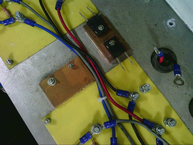 Cheers, �Tony. |
||||
LadyN Guru Joined: 26/01/2019 Location: United StatesPosts: 408 |
Instead of bolting directly to aluminum, using copper intermediary is to help dissipate heat better? (Copper has a higher thermal conductivity) How much of a change does this have on the life/performance of the MOSFET? |
||||
| Warpspeed Guru Joined: 09/08/2007 Location: AustraliaPosts: 4406 |
Without the copper, all the heat concentrates into a very small area of some fairly thin aluminium. With a copper plate, the heat is spread over a far wider area into the aluminium. [quote]How much of a change does this have on the life/performance of the MOSFET? [/quote] Probably not much, unless you are really pushing the absolute limits of junction temperature. I suppose it depends on your appetite for risk. Cheers, �Tony. |
||||
| BenandAmber Guru Joined: 16/02/2019 Location: United StatesPosts: 961 |
God bless Australia a big thanks to all you guys down under I was reading somewhere that the legs of a mosfet got the hottest Warpspeed could probably fill us in on that one And another silly thing I've been thinking about is putting the whole board in Transformer oil be warned i am good parrot but Dumber than a box of rocks |
||||
| BenandAmber Guru Joined: 16/02/2019 Location: United StatesPosts: 961 |
Sorry if I've gone off topic be warned i am good parrot but Dumber than a box of rocks |
||||
| kentfielddude Regular Member Joined: 09/05/2019 Location: United StatesPosts: 89 |
Silver is the best thermal conductor. This heat sink should ensure you don't run into any overheating issues. 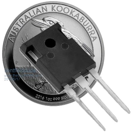 |
||||
| Warpspeed Guru Joined: 09/08/2007 Location: AustraliaPosts: 4406 |
Everyone should own some silver............................ Cheers, �Tony. |
||||
| wiseguy Guru Joined: 21/06/2018 Location: AustraliaPosts: 990 |
Hi Mark, Thanks for your interest and suggestion, I did a complete survey of Ali when I chose the connectors. For the Battery & Choke connectors I am going to use tinned red copper solderable lugs they are 1.5mm thick, the ones you suggested are 0.8mm tinned brass and they worried me a bit for higher currents, but I welcome suggestions like this ! If at first you dont succeed, I suggest you avoid sky diving.... Cheers Mike |
||||
| wiseguy Guru Joined: 21/06/2018 Location: AustraliaPosts: 990 |
I agree the copper suggestion would draw in and spread out heat the best, but in the past I have found it difficult to tap. Is it easy to buy in bar form and I imagine fairly expensive? If it ever comes to immersing my electronics into transformer oil to keep it cool I'll take up another interest, that doesn't even rate as a last resort. I might consider a radiator and circulating liquid through tubes and a thermal exchanger with FETs on it but that would be my last resort. Its no coincidence that the standoffs are all inline (~10mm high) I already pictured a long copper or aluminium bar from end to end, tap them in the centre for M5 or 6 and bolt the power inputs directly to the middle of the bus, lots of options. If the HY4008's are happy in parallel without oscillations they can be bolted direct onto aluminium Bar I have lengths of 25 x 10mm xsection with one long and 2 shorter pieces. The long one is the + connection, the shorter ones are the choke connections again if tapped you could bolt directly to them. Then with strips of silicon pad bolt the Bars to a heatsink (with insulation for the bolts) and we have better thermal behaviour than individual pads on the FETs. All this fun still to be had...... If at first you dont succeed, I suggest you avoid sky diving.... Cheers Mike |
||||
| wiseguy Guru Joined: 21/06/2018 Location: AustraliaPosts: 990 |
I prefer the bigger FETs when dealing with lots of energy & current. There are some pretty amazing TO220 mosfet specs but it doesnt sit comfortably with me when you put them alongside a TO247 package - cause they look tough! I have not used any electronic engineering data to back this up, consider this a gut feel or anecdotal assessment! I also like the mounting of TO247 and the surface area for heat transfer and yes the legs are much more substantial - If I have the space I will use TO247 any day. If at first you dont succeed, I suggest you avoid sky diving.... Cheers Mike |
||||
| BenandAmber Guru Joined: 16/02/2019 Location: United StatesPosts: 961 |
That gut feeling means a lot coming from you WiseGuy By the way I appreciate the advice you gave me a when I first came on here And I've read a few post that you commented in I can see you definitely do not need to have a board in your hand or even see a board for that matter to know how it works be warned i am good parrot but Dumber than a box of rocks |
||||
| wiseguy Guru Joined: 21/06/2018 Location: AustraliaPosts: 990 |
Ok now for some transformer discussion on my ebay purchase. The ad reads "5000W 240AC to 38V 80A toroidal transformer" 2 available. Here is a picture from the AD. 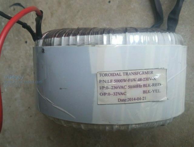 Other text from the ebay posting read: Transformer removed from working device (LF 10000W off-grid inverter). 230VAC to 32VAC/80A 240VAC to 38VAC/80A or 32VAC to 230VAC/16A 38VAC to 240VAC/16A Size: D170 x H100 mm Weight: 10 kG I emailed him suggesting there is an issue with the text in the ads. There are 2 wires for primary and 2 for secondary - no taps. It cant be 230-32 & also 240 - 38, they are different ratios. I also pointed out that ot cant be 5kW and also 32V x 80A as that is only 2.56kW. Also 230 x 16A = 3.6kW. The transformer finished dimensions are actually closer to OD 160mm, ID 55mm, H 90mm. Weight is ~ 9.7kG Compared to an Aerosharp I have is OD 195mm x ID 55mm x H 70mm. weight 11.2 kG. I suggest that the sticker is either 5kW for both transformers or a peak value for 1 transformer it just doesnt feel like a 5kW toroidal. The cost was $180 for the 2 delivered. I ask for comments, the transformers arrived yesterday I brought 2 hoping for the 10kW in the AD but I have a gut feel these are only good for 2 - 3 kW each. I will post the test data soon which is excellent. But do I complain about them or just let it slide and accept them for what they are ? I am disappointed but also know the value I paid is probably about right even if they are only good for say ~ 6kW in parallel ? Test data posted shortly. If at first you dont succeed, I suggest you avoid sky diving.... Cheers Mike |
||||
| renewableMark Guru Joined: 09/12/2017 Location: AustraliaPosts: 1678 |
how much were they? Cheers Caveman Mark Off grid eastern Melb |
||||
| wiseguy Guru Joined: 21/06/2018 Location: AustraliaPosts: 990 |
Hi Mark I edited it after you read the post as I realised I forgot to say, $180 delivered for the 2 toroids. If at first you dont succeed, I suggest you avoid sky diving.... Cheers Mike |
||||
mackoffgrid Guru Joined: 13/03/2017 Location: AustraliaPosts: 460 |
Mike, I think you did fine, as long as you don't have to modify them. 2 x 9.6kg wound transformers for $180 -  Yes, I'd agree that you've got 2500ish VA. Do your testing with them and if you need to do larger, sell them off to someone who really can't handle the transformer winding. |
||||
