
|
|
Forum Index : Electronics : Chinese Inverter Board - voltage feedback and other ?'s
| Author | Message | ||||
| Davo99 Guru Joined: 03/06/2019 Location: AustraliaPosts: 1578 |
Bought all mine there although I have got a few now I was assured worked but did not. Also bought a Lot of panels off that site although so many people are just plain stupid about the prices they want for them. Getting so many for free now I'm giving them away to other people! :0) |
||||
| FFTandMe Newbie Joined: 11/10/2019 Location: CanadaPosts: 32 |
Hey all! Sorry for the long absence. Life and the pandemic made me take some time away from hobby projects. Anyhoo, I ordered that toroid from Ebay a couple of months ago rated for 3000va as I wanted to try my hand at winding a core. From what I found on ampacity of wires a 10AWG (5.3mm^2) wire would carry 30 amps no problem and surge to 50 amps when needed. Since my house power is 120v I figured this would be more than adequate. However, on arriving and trying to wind it onto a shuttle and subsequently onto my core it turned out to be an utter disaster. I just do not have the finger/hand strength to adequately tighten the windings around the core and keep them straight. I made two attempts and after about 15 or so windings of that super-stiff wire the core looked horrible and was heading toward disaster. Expensive mistake I suppose. From what I can see on various charts I can get sufficient amperage by using 16AWG (1.3mm^2) 3 in hand. Engineering Toolbox says this (single core) wire can carry 15 amps maximum so it would be loosely equivalent to a the 10AWG i wanted to use (I chose the 10 AWG because I wanted to be able to handle surge currents and not deal with the complexity of winding multiple wires in hand- found out the hard way that this was not the easier way to wind). In any event trying to wind 5.3mm^2 wire was an expensive mistake that I would really prefer not to repeat. So I'd appreciate advice on a good way to wind this core rated for 3000VA so that when I am done experimenting with this smaller board I can seamlessly move the core to a bigger board that can utilize its size. Should I go 3 in hand 16AWG (1.3mm^2)? Two in hand 14AWG (2.1mm^2)? Thanks! |
||||
| Warpspeed Guru Joined: 09/08/2007 Location: AustraliaPosts: 4406 |
About the thickest wire a real hero could deal with might be around 2mm diameter or 3.14mm squared, and it would end up being a pretty lumpy winding. Anything thinner than that becomes a lot easier very quickly. Huge difference between winding with 1.8mm versus 2.0mm diameter for instance. The best way to do it (at least for higher voltage windings) is to wind in layers, one wire at a time, and then finally parallel up as many layers as needed. A conservative rule of thumb for current density in a large transformer, would be four amps per mm squared. Temperature rise goes up square law with current, so every 40% increase in current doubles the temperature rise. That gets high really quickly. I would not be planning to push more than 20 amps continuous through 5.3mm squared, thirty amps for maybe a few minutes at a time perhaps. Fifty amps.... I don't think so, at least not in a transformer. A straight run of 5.3mm squared cable is a very different thing to closely packed turns that end up being a solid lump, where the heat generated cannot readily escape from deeply buried turns. Cheers, ĀTony. |
||||
| FFTandMe Newbie Joined: 11/10/2019 Location: CanadaPosts: 32 |
Hi Warpspeed, I appreciate the response both for the information and for doing it a way that didn't kick me when I was already down lol :) My plan for 50 amps was solely for heavy inductive load startup, not for any significant period of time. To make sure I understand what you're saying, your plan is to wind one wire completely around the toroid, and once I make it around, start a second winding completely around the toroid once. After I've done my X number of windings then put them together in parallel. Did I understand this correctly? If so, wouldn't you use slightly more wire in the 2nd winding versus the first, and hence cause an imbalance in the output where the inner winding carries slightly more current due to internal resistance? If its not a significant factor then I would love to do that method as my frustration level with winding wire would be orders of magnitude less with thinner wire. Also, if I need more than one complete revolution around the toroid to get the number of turns I need, do I start a second layer to complete the number of turns I need and then "pick up where I left off" to start the next coil I'll parallel in? I have about 2.5-3kg left of 18 gauge (0.82mm^2) wire from other projects (I bought in bulk because "you never know"- this time it might have paid off!). I could use that to start winding the coil while I get more ordered in. If I used this easy to wind material, then my math says 3000va at 120v means I can ballpark 25amps continuous. Using your rule of thumb of 4amp/mm^2 then I would need 7.6 so we'll round to 8 complete coils worth to carry the continuous load I want. Based on how malleable the 18 gauge wire I have is, I have much higher confidence in being able to coil that up and since I already have some on hand I can see just how neat and pretty and I can start making layers. Thanks again for your advice. I appreciate it. |
||||
| BenandAmber Guru Joined: 16/02/2019 Location: United StatesPosts: 961 |
There is a S3 power jack Transformer on ebay I think it is 69 bucks that includes shipping In 2014 powerjack used the s4 in 8000 watt inverter Thay now use the S4 for the 8000 watt inverter Warpspeed "one of the greats"would tell you that that S3 is good for somewhere around 2,000 Watts continuous I have seen the s3 run at over 3000 Watts If you love your family I would go with warpspeed He was designing inverters before I was born "unimaginable wisdom" That Transformer is listed as 24 volt low side primary is easy Maybe you could use it in your first smaller inverter it could be your back up inverter I put two large 18000uf caps on mine and built up the traces It has had no problems it is suprising what it will start! It would be asome if you could get another 3000 watt core and stack them together for your next primary inverter It will be a little easier to wind that 10g wire My wife had to help me I have very little filling in left hand and it is weak You take it outside and wind by pulling wire through without a shuttle it takes a while and lots of walking but it is easy to get it straight and tight It can be spread out little at a time over several days so you dont get burt out on winding Less or no solder joints also!! Once you get fist one done you will be ready to build a bigger one This stuff is addictive and with these prebuilt boards you don't have to be a expert As long as you can get some advice for a great when you need it Cant wait to read about your success I have lots of Parts if I can do anything for you just let me know!! be warned i am good parrot but Dumber than a box of rocks |
||||
| BenandAmber Guru Joined: 16/02/2019 Location: United StatesPosts: 961 |
 Edited 2020-04-13 10:16 by BenandAmber be warned i am good parrot but Dumber than a box of rocks |
||||
| Warpspeed Guru Joined: 09/08/2007 Location: AustraliaPosts: 4406 |
The starting point of any transformer design will be knowing the physical dimensions of the toroidal core. From that we initially work out how many secondary turns will be required to produce our target flux density (1 Tesla or 10,000 Gauss). Once we know the inner circumference and the required number of turns, we can start looking at different wire gauges that will be a nice convenient fit into the available space, and not too thick to work with. This usually all works out pretty well for a 220v transformer. For a 110v transformer the wire will end up being far too heavy to fill one layer with so few turns. So we wind two 110v windings, each occupying slightly less than half the circumference for one layer. So first layer we get two separate 110v windings. We keep adding layers one above the other until we have used up half of the available area through the original toroid hole. At that point the hole remaining should theoretically be 70.17% of what the original hole diameter was in the original bare toroid. We don't need to worry about different layers having different lengths of wire, there will not be exact current sharing, but the difference will not be enough to cause concern. The turns count of each layer absolutely must be exact, and we test out transformer at the completion of each layer to make absolutely certain that we are never one turn short or one turn extra. We base all our design on the inner most layer which will have the shortest circumference. Whatever turns will fit there sets the turn count for all the layers that went on previously. So we need to plan ahead. That is not as difficult as it sounds, because the magic of geometry tells us that for each layer, the space shrinks by exactly six turns for each subsequent layer. So we work out the number of turns that will fit onto the inner tightest layer, and how many layers will fit onto 29.83% of the original toroid hole diameter. So knowing the wire gauge, how many layers and the 4 amps per mm squared, that gives us our final safe transformer rating. So to start the ball rolling, I need to know all of the dimensions of the bare toroid, and I will assume this is for 110v 60Hz. Cheers, ĀTony. |
||||
| FFTandMe Newbie Joined: 11/10/2019 Location: CanadaPosts: 32 |
Hi BenandAmber, Thanks for the info and the feedback. Part of this is the learning process for me and getting a better understanding of things. I also like the idea of accomplishing a transformer wind myself. I have a good feeling its something in my capabilities so I want to give it a shot. If I lived a little further south I might give doing the winding without a shuttle a go, but here the weather is still pretty bad. We had our warmest day of the year so far and I think it only hit 9C (48F). We're also at that time of the year where getting consistent good weather has low chance. We had a sunny day today but not before having 3 days of clouds and light rain, and tomorrow will start another 3 day stretch of clouds/rain before another sunny day. I just dont have good enough, consistent weather to unwind 90-100m of wire and walk it through the core. I'm also solo on this project complicating making tight winds with this ungodly thick 10ga wire. If the idea presented by the guru Warpspeed is viable my success both from a practical and aesthetic perspective will increase dramatically if I can use multiple lighter gauge winds in parallel. As for parts, I'll keep that in mind. For smaller parts (caps, mosfets, etc) its not going to be crazy expensive to ship to Canada. Thanks for the offer! |
||||
| FFTandMe Newbie Joined: 11/10/2019 Location: CanadaPosts: 32 |
Hi Warpspeed, I read through your post a couple of times and I think I need to read it again to get a better understanding, but to answer your questions: 1) House voltage here is 110-120v. ĀUsually as voltage sags on the battery so will voltage, so I was shooting for 120V on my transformer (most electronics here in North America work just fine on 110V. ĀMy house current right now is hovering at 119V). 2) The frequency is 60Hz 3) The toroid dimensions are: ĀID - 91.5mm, OD - 183mm, H - 51mm (or if you prefer the Queen's language: ĀOD - 7.2", ID - 3.6", H - 2") based on the material used and the calculator the seller provided, the TPV is 2.2. Thanks a ton for your help! Edited 2020-04-13 10:49 by FFTandMe |
||||
| FFTandMe Newbie Joined: 11/10/2019 Location: CanadaPosts: 32 |
Hello again warpspeed! I think I dig where you're going with the calculations. Let me know if I am on the right path. This is a bunch of thinking out loud so I am probably going to go down wrong paths.... If we are starting with the diameter that is ID/sqrt(2) (I think that's where you were going with the 70.71% thing) then I get the innermost wind being wrapped around a diameter of 64.7mm which is a circumference of 203.26mm. If we want a 120v winding and have a TPV of 2.2 then we need to be able to fit 264 winds round that circumference. So, 203.26/264 = 0.77mm dia wire. Here 18 gauge is 0.82mm so it might be close enough to use 18 gauge wire and it would make it around the innermost diameter one revolution. The problem might come we wont get an entire fill with that gauge. 91.5-64.7 = 26.8/2 = 13.4, so to get the fill desired with that gauge wire we would need 13.4/0.82 = 16.34 so round down to 16 individual coils in parallel of 18 gauge wire. That may not be so bad as that would more than handle the amperage that I want to put through it. We could go with thicker wire to start but it would be impossible to wind the entire coil in one layer so we would have to use some of the other ideas you presented. How'd I do? Cheers! |
||||
| FFTandMe Newbie Joined: 11/10/2019 Location: CanadaPosts: 32 |
Warpspeed - I forgot to mention I did wrap another layer of insulating tape (rated to 500C) on the core in addition to the layer provided by the seller, so the ID may have shrunk a couple of mm, but the bare iron itself is the dimensions I listed. |
||||
| Warpspeed Guru Joined: 09/08/2007 Location: AustraliaPosts: 4406 |
O/k, starting point is core cross sectional area which is 45.75mm x 51mm = 2,333mm sq. Or 23.3 cm square. Now we go to an online flux calculator program https://www.electricaltechnology.org/2014/02/maximum-flux-density-bmax-calculator.html Enter the following values: V rms 120v Frequency .00006Mhz (four zeroes) Turns 193 Core area 23.3cm sq That gives us a result of 1.0017 Teslas. To get that, we use trial and error for the turns until we get close to 1 Tesla (its not critical). So 1.6 turns per volt will do us very nicely in this design. So we want to end up with roughly equal copper areas through our hole for primary and secondary, so copper conduction losses should end up being very roughly equal between primary and secondary. If we divide our hole into two separate areas, the primary should use up the middle part and stretch out to .7071 (root 2.0) of the hole diameter. Our hole is 91.5mm diameter. So the outside diameter of the combined middle primary winding should be 91.5 x .7071 = 64.7mm diameter. The inner most winding of the secondary might have a diameter of about maybe 65mm. The circumference of that winding will be 65mm x pi = 203mm. We need to fit 193 turns into that space for one 120v winding, and I think 1.0mm diameter wire is about all that is going to fit. Now our original hole is 91.5mm diameter and if we keep adding layered windings of 1mm wire onto that in theory it would take 13 layers to reduce our hole diameter to 65mm. In practice you might only be able to get 10 or 11 layers before the remaining space for the primary starts to get too small. A wire size of 1mm diameter is .7855mm sq, and four amps per mm sq gives us 3.142 amps per layer. Eleven layers would be 34.5 amps continuous. At 120 volts = 4.147 Kw. Ten layers works out to 31.42 amps = 3.77Kw. So there it is. Possibly eleven layers of 1mm diameter wire with 190 turns (to be safe) for each layer would make a very nice 4Kw transformer. The very first layer is going to look awfully spread out with 190 turns wound right around that hole as it has a starting circumference of about 287mm. But every layer it gets a little bit tighter. By the time the final layer goes on and the hole is only 65mm diameter, its going to be mighty tight fitting those 190 turns on, but with care and patience it should fit. Cheers, ĀTony. |
||||
| FFTandMe Newbie Joined: 11/10/2019 Location: CanadaPosts: 32 |
EDIT - Warpspeed cross-posted as I posted this. disregard. Edited 2020-04-13 12:07 by FFTandMe |
||||
| Warpspeed Guru Joined: 09/08/2007 Location: AustraliaPosts: 4406 |
If you are wondering why the transformer supplier recommended 2.2 turns per volt, there are two reasons for that. Some users will be operating at 50Hz not 60Hz, which increases the flux in the core by 20%. The other reason is that the grid supply voltage can be 15 percent higher or lower than spec. If the grid happens to be 15% high, that will further increase the flux in the core by fifteen percent. We do not need to worry about either of those problems, so 1.6 turns per volt is fine for 120v at 60Hz in our inverter. If it was 120v at 50Hz we would need 1.6 x 1.2 = 1.92 turns per volt. If it was 120v +15% (138v at 50Hz) we would need 1.92 x 1.15 = 2.208 turns per volt. So the supplier of the toroid has covered his arse so that if the safer figure of 2.2 turns per volt will work for anyone anywhere in the world without any problems. Its really overcautious, and we can do a little better than that. We can usefully reduce our turns and use thicker wire and increase our maximum power rating to up around 4Kw, which is nice Ā  Edited 2020-04-13 12:42 by Warpspeed Cheers, ĀTony. |
||||
| FFTandMe Newbie Joined: 11/10/2019 Location: CanadaPosts: 32 |
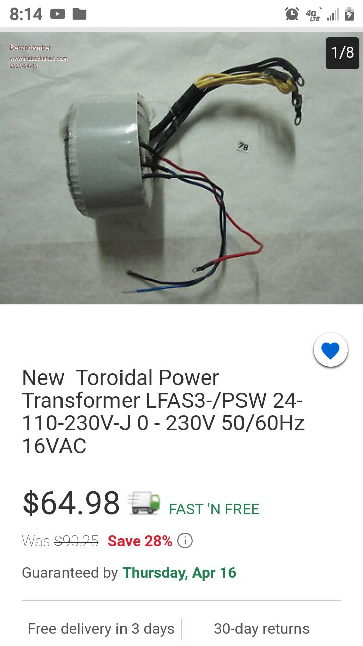
Hi Warpspeed (may I call you Tony?), Thanks so much for the calculator! The calc is clear and makes total sense, so thank you for that! I found several errors in my calculations (using area when I should have used diameter) but by some miracle got the same result (about 11 layers). Let me say now that I completely believe and trust your calcs. That being said, I don't understand why the vendor would say this this core had a 2.2 TPV. My independent calcs using rough guides I found on the 'net came much closer to your value of 193 (i.e. 1.6 TPV). If you like I can attach the spreadsheet he sent me for doing calculations. I'm also including a snippet of his ad where he mentions some tech info about the core. Regardless, my initial rough calcs for TPV combined with your calculator and results give me confidence that a 1.6 TPV is the better number to use. If you have any thoughts on why he would say 2.2 I'd be interested to hear them. (I also have a question about the other winding after the quote) My battery system is a 24v lead acid system. Based on the specs of my battery I really don't want the voltage of each individual cell to go below 1.79v or a low voltage cutoff of 21.5v. 21.5*0.7071 = 15.20v. Using a TPV of 1.6 that means the secondary should have 24 turns. Having 11 x 0.82mm&2 (1.0mm dia) primary wires is 9mm^2 total area. So that implies I need to have at least 45mm^2 wire for the primary (7.6mm dia which is roughly 1ga) to match it up. I take it since we are dealing with HUGE cables its not a problem to use insulated wire as long as we can make the turns fit in the area we have left, nor it is crucial to mould to the contour of the toroid the way it was with the primary? |
||||
| FFTandMe Newbie Joined: 11/10/2019 Location: CanadaPosts: 32 |
LOL Warpspeed you answer the question was I was proofing my post! LOL!!! Thanks again for your insight! ĀI'm really glad what I have on hand is actually perfect to start winding. ĀI'm going to use one of the many online calculators to measure out how much wire I need to put on a shuttle and I'll be getting to winding tomorrow during the rainy day. I want to let you know that I am truly grateful to you, poida and benandamber. ĀAll of you have been such a great help and I wish I had been more willing to ask for some sanity checks before I pointed and clicked to wasting money (although I might be able to use the 10 gauge after all for the other part of the transformer, just use a few in parallel). Cheers, David Edited 2020-04-13 12:47 by FFTandMe |
||||
| Warpspeed Guru Joined: 09/08/2007 Location: AustraliaPosts: 4406 |
O/k so minimum dc voltage 21.5v. So assuming no losses anywhere, from that 21.5v, we might be able to generate a sine wave with a peak voltage of 21.5v that equates to around 15.2v rms at the primary. So our transformer ratio needs to be 15.2v rms to 120v rms or 7.89:1 There are two conflicting factors when deciding on a turns ratio. There are going to be voltage drops and losses everywhere under any kind of reasonable load, but on the other hand we don't really ever want to let the battery ever get that low. The general consensus on the Forum here determined over many years of the combined experience of many people, with 48v inverters generating 240v, that 8:1 is an optimum value. Your voltages will be half that on both sides, so the 8:1 figure is probably the one to aim for. If secondary turns are going to be 190, then a 23.75 turn primary is suggested. I would think a 24 turn primary should turn out to be be just about right. Cheers, ĀTony. |
||||
| FFTandMe Newbie Joined: 11/10/2019 Location: CanadaPosts: 32 |
I am going to sleep a very happy man. ĀThanks so much Warpspeed! EDIT - yes, I agree I wouldn't want to let the battery get that low. That choice was to factor in losses and if I happened to have to run the batteries low due to low power generation (that value, dpeending on the draw, puts the battery between 80 and 95% DoD). My problem is to factor that 8:1 ratio while not having an overvoltage condition. Either way, I have a clearer plan than I had when the threw the shuttle into the corner of my workspace in disgust earlier today and for that I am grateful! Edited 2020-04-13 13:18 by FFTandMe |
||||
| Warpspeed Guru Joined: 09/08/2007 Location: AustraliaPosts: 4406 |
The more turns there are on the primary, the lower the primary current for any given secondary current, so theoretically, efficiency and conduction losses can be slightly lower. But then at some stage, the battery gets a bit low, and the inverter drops out of voltage regulation, so fewer turns on the primary can help with that situation. So its really a judgement call, and if you put it to a vote, eight to one ratio for lead acid batteries seems to be what most people here finally end up with after a bit of testing and experimentation. Its not a big deal to add or remove one turn, provided there is enough length and space left on the toroid to do it with. Yes its always great to see a definite way forward with any project. Just keep adding more secondary layers until you reach 65mm inside diameter and the gap between the ends of each winding start to close up. The more layers, the higher the power rating, so just keep going. How many layers you finally end up with is difficult to guess, but its going to be a lot fewer than thirteen. Cheers, ĀTony. |
||||
