
|
|
Forum Index : Electronics : 150V 45A MPPT - roll your own
| Author | Message | ||||
| noneyabussiness Guru Joined: 31/07/2017 Location: AustraliaPosts: 506 |
thank you, I did calibrate it originally hooked up to bench supply... but going of the values I was getting this morning, ether the current sensors I have installed are inaccurate or ( most likely) I've stuffed up the calibration, output current was higher than input via wattage on screen... Ill let it run for a bit and bench it again to calibrate it.. but on a positive note, by the lcd it was delivering about 2.6kw for about half an hour at its peak ( around 2.2 - 2.4 constantly), done 11kwh today so far...and inductor was warm, I could hold it, and mosfets were barely warm (41�c - 42c max by the sensor) ... attached is a pic from earlier ( around 11am) .. by the amout of panels connected thats about right too.. 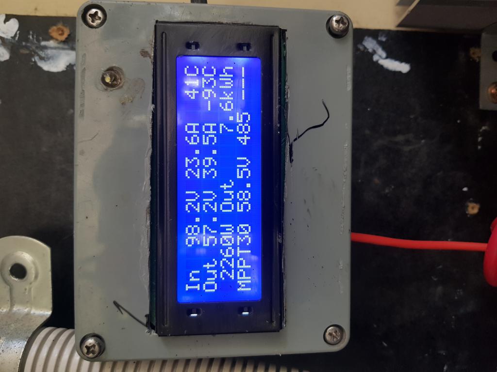 I think it works !! |
||||
| noneyabussiness Guru Joined: 31/07/2017 Location: AustraliaPosts: 506 |
this is a soak test of components, I'm going to box it up and calibrate it better .. but so far really happy, it is replacing a cheap mppt controller that went to silicone heaven... but this one is HEAPS better so far, runs much cooler and no noise... I think it works !! |
||||
| poida Guru Joined: 02/02/2017 Location: AustraliaPosts: 1389 |
Noneya: for sure I calibrate it when running using a DMM. connect using the serial port, get the menu.. check Vin, cal Vin using DMM reading. check Vout, cal Vout using DMM reading. Now, to get a good calibration for the current sensors I use a cheapie UNI-T device such as UT-203 which has a DC current feature, 0-40 Amps using it's clamp thingie. I always zero it when I hold it in the nearly identical position where I will measure the current. Then I put the clamp over the positive lead and see what I see. Tell the firmware the reading. I think if we get +/- 5% accuracy then we are going well for current readings. Oh, and you can repair this one, not that will blow up very often... As you can see in the previous post, I have 2 of these and they've done nearly 8MW.hr of work. I like them a lot. I sold the 60 Amp Morningstar MPPT on ebay for cheap once I saw how well they work. It's just a big-ass DC-DC converter with a bit of brains when it's all said and done. The MS 60A mppt goes for what now? this vendor has it for #1360 AUD A 45 Amp version is $1130 AUD OK. Fine. One thing I saw in the internet was reports that you DO NOT EVER WANT TO send commands to stop and start the MS controller using modbus commands. You will blow it up. And it's potted up with tough silicon gunk and not repairable. FUK DAT SH1T. These mppt builds are good for 45 Amps and probs good for 60 Amps with a good choke and large enough heat sink. All for about $150 or less. And we can repair them. wronger than a phone book full of wrong phone numbers |
||||
| Murphy's friend Guru Joined: 04/10/2019 Location: AustraliaPosts: 584 |
Yes, those MPPT's do work well. Mine has passed the 2500KWh mark a while ago. I found the choke gets warmer than the big heat sink I'm using, I have a 80mm fan blowing straight at the choke and this works well enough on days when its 36 degrees in my shed. When you box it up and it's in a metal case, keep the display opening a few mm away from the screen. I found it interferes with the display otherwise. |
||||
| noneyabussiness Guru Joined: 31/07/2017 Location: AustraliaPosts: 506 |
lol... I have a couple of pedestal fans on oscillate in front of the general area... no fans on the unit at all... still didn't get very warm, even pushing the power through it that it was... I'll get some photos tomorrow of the unit itself, but REALLY happy .. these are awsome I think it works !! |
||||
| noneyabussiness Guru Joined: 31/07/2017 Location: AustraliaPosts: 506 |
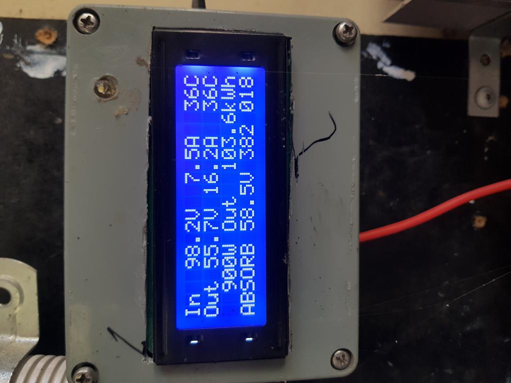
 Here's a pic of the actual unit, the inductor is wound with 11 turns of 4mm solar wire( had some spare) the cores were salvage .. reads 120uh on my cheapy meter... 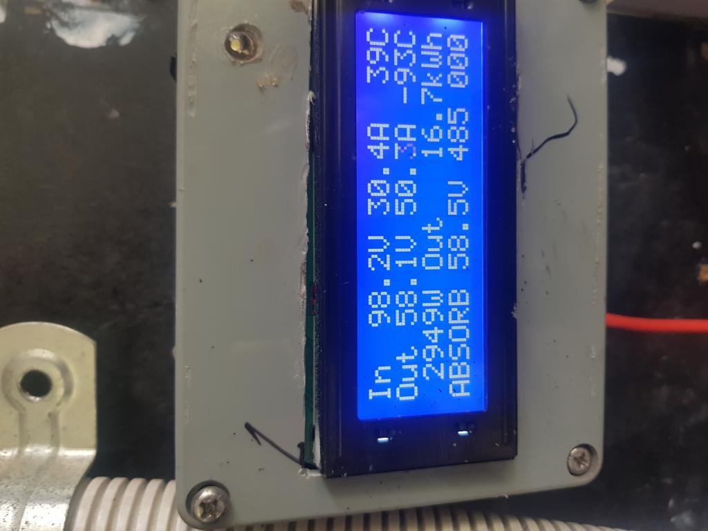 decided to max it out , pushed 3.1kw for quite some time but hovered around this most of the time as batteries were getting full.. again, inductor was the " hottest " , warm but could hold it.. mosfets were barely warm, temp sensor on unit read between 40-42 ...no fans on it, but i do have 2 cheapy pedestal fans oscillating on general area, used mainly for the OGI's .. I think it works !! |
||||
| Murphy's friend Guru Joined: 04/10/2019 Location: AustraliaPosts: 584 |
Hmmmm, 50.3A through 4mm sq solar cable and it does not get hot? Are you kidding me, surely that does not sound right. I think it's time I'll introduce you to a decent choke. Salvaged from an Aerosharp inverter you get at least that many turns but with 2.5 times (10mm sq) wire area. The existing coils are wired in parallel:  |
||||
| poida Guru Joined: 02/02/2017 Location: AustraliaPosts: 1389 |
oh yeah, THIS is what we are talking about. The entire project was to my mind seeing what junk we have lying around that we could use to replace $1,300 units. The inductance is not the only thing that is important, you need to also know if it is saturating at the working conditions you are employing. I am lucky to have a good DSO and current sensors so I can prove the choke is not saturating in use. 3kW and 120uH seems "about right" but if it's getting hot and the efficiency is not that great (maybe lees than 90%) then maybe the choke is saturating. For a small cost of switching losses, you can halve the work load of the inductor. Just move to 40KHz PWM from the menu. Maybe you will see less heat in the choke and a tiny more on the heatsink.. From the numbers above I see 98.2 x 30.4 = 2985 Watts input and 58.1 x 50.3 = 2922 Watts output. efficiency of the DC-DC conversion is 98% and that is fantastic. wronger than a phone book full of wrong phone numbers |
||||
| noneyabussiness Guru Joined: 31/07/2017 Location: AustraliaPosts: 506 |
it is !! this was a soak test , I'm winding up a more " appropriate " inductor at the moment but you did a great job poida !! aiming for about 200uh with little to no heat / saturation using proper magnet wire. the mosfets are out of the DC side of those eltek PS ( 150v rated), Ill get some numbers tomorrow .. I don't have the tools you do, but I figure if everything runs reasonably cool ( not " cold " but warm) I figure it must be right ... now comes the fun !! considering the power going through it( I know the current measurements are probably out, but not by a huge amount, its still in the ballpark) and the fact that it doesn't even have forced cooling.. just " residual " from pedestal fans is a real show on its capabilities..like you said, using MUCH cheaper components ( a lot of mine are salvaged), replacing 1300 buck devices... AWESOME!! I think it works !! |
||||
| noneyabussiness Guru Joined: 31/07/2017 Location: AustraliaPosts: 506 |
 cracked 100kwh.. no problems... had a couple of crappy rainy days.. Pete do you have any more boards at all ?? wanna set up another... I think it works !! |
||||
| poida Guru Joined: 02/02/2017 Location: AustraliaPosts: 1389 |
No boards left. I have 2 test boards, assembled and working. One is Nicks' PCB, with only a few caps fitted. I use this to test how much capacitance is needed and what shows up when there is not enough. The other is a fully populated Wiseguy PCB. Maybe I need to get another batch made. Wiseguy's design I think. They were about $10 each, maybe more now. I could also get a few inverter boards with the order to combine freight. I best make a new thread here asking all of us who wants a PCB? Are you in any hurry? I can loan you the Wiseguy board while the PCBs get made. wronger than a phone book full of wrong phone numbers |
||||
| noneyabussiness Guru Joined: 31/07/2017 Location: AustraliaPosts: 506 |
hey poida, no rush here, Im happy to get a few if there is a minimum board count... re. inverter board, I don't think I need any as I only have 1 partially populated at mo, and still have another 3 left .. but if you getting some power boards ( " mosfet boards ") then I would be very interested in getting a couple of them...not sure if madness still doing his.. thank you again for your help with this... I think it works !! |
||||
| poida Guru Joined: 02/02/2017 Location: AustraliaPosts: 1389 |
Wiseguy, I have tested the perfect symmetrical output today. First I had to alter the test inverter to make it give a bit of noise. Changed the 100uH choke to a 22 uH with no change to the cap. Now the 1.5kW toroid makes a nice amount of noise at idle. The original firmware, that has the few pulses in the wrong places uses 0.34 A at idle with a 51.4V supply Running the new firmware, there is no noise and the same idle current. AS usual, the DSO is educational. Yellow is 50 Hz sync pulse Dark Blue is AC output voltage Purple is primary winding current. (about 1 Amp/div) Old firmware:  The new code with nice symmetrical pulse train: 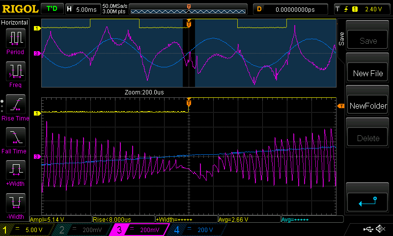 First, I average 4 triggered captures to reduce noise so the top current traces look weird. Second, I triggered on different zero crossing for the 2 versions of code. One when rising, one when falling. It does not matter. The key thing to see here is to compare the two bottom traces of the current. In the center is the zero voltage crossing and we can see with the old code a bump of current is produced right after zero volts. With the symmetrical code, there is no bump. I think this means it's as good as it can get. IF you look closely, using your good eye, I think we can see evidence of oscillation excited by the bump of current that is injected at zero crossing. I see the first, large bump, then I see it faintly echoed afterwards. The period is about 2 divisions so that's 400uS. This is a frequency of 2,500 Hz and we all should be able to hear that. This is quickly damped though, so we hear it started up for a few cycles each time the voltage crosses zero. Here is the symmetrical code, without trace averaging, to show what the primary current is really doing during the 50Hz waveform. I do not like potentially misleading people.  I replaced the 100uH choke, to see if it's the same. It's the same, but with 1/4 of the current so the Purple trace is 1/4 the height. old code:  new code: 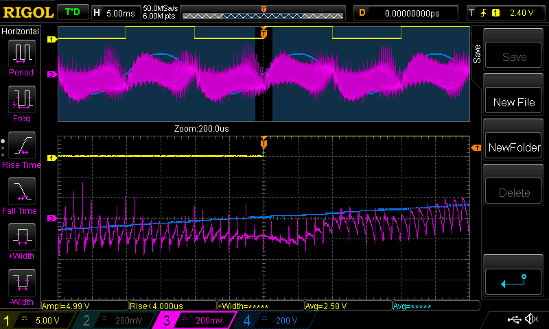 When running with the new code and the 100uH choke, the torid is silent. This is very dangerous for me since there is no audible warning the inverter is running. It's so quiet now... Here I show the symmetrical code under a light load, 100W.  wronger than a phone book full of wrong phone numbers |
||||
| KeepIS Guru Joined: 13/10/2014 Location: AustraliaPosts: 1372 |
That is just brilliant poida, what more can one say  It's all too hard. Mike. |
||||
| noneyabussiness Guru Joined: 31/07/2017 Location: AustraliaPosts: 506 |
friggin brilliant bloke... I think it works !! |
||||
| andymc70 Regular Member Joined: 30/06/2019 Location: AustraliaPosts: 42 |
Hello I just wondering if you have an image of the other side of the choke. Trying to work out how they are wired and then connected. I am about to make my second MPPT and I might see if I can use this style. I have rewired the core from the same choke and the choke is a pain to unwind. Thanks Andy |
||||
| wiseguy Guru Joined: 21/06/2018 Location: AustraliaPosts: 1000 |
Peter, great results I was confident it could be done thanks for your efforts and time and perseverance to get it happening and tested. I am excited & really looking forward to trying it out. Unfortunately, that is a week or two away yet. I am busy with my recent project you are aware of & trying to reduce my street consumption to zero or at least until my energy storage is totally depleted. Next project, I am going to build a purpose built wheeled trolley which will house the energy storage, Nano Inverter and Grid feed inverter in a self contained block, with a single connecting lead & 3 phase plug and a few switches. That should tidy up all the cable & switching rats-nest mess I currently have. Edited 2023-01-21 13:13 by wiseguy If at first you dont succeed, I suggest you avoid sky diving.... Cheers Mike |
||||
| Murphy's friend Guru Joined: 04/10/2019 Location: AustraliaPosts: 584 |
Other side?? Just wires there, no connections. Your eagle eyes might note that I have unwound the original wire, straightened it (quite a job) and then re wound two in hand to double the current @ half the number of turns per coil. Both windings are identical and were connected in parallel as the picture shows. |
||||
Bryan1 Guru Joined: 22/02/2006 Location: AustraliaPosts: 1211 |
G'day Poida, Now I do know this MPPT is for a 48 volt system and as still run forklift batteries after 12 years my aim is to see if I can get 20 years out of them. So I do assume this MPPT can be made for 24 volts with just a firmware change. Cheers Bryan |
||||
| nickskethisniks Guru Joined: 17/10/2017 Location: BelgiumPosts: 416 |
I missed the magical moment today, but my unit hit the 10MWh mark!  ( btw. I don't recommend running the unit that high in power, mine is maximum active cooled) 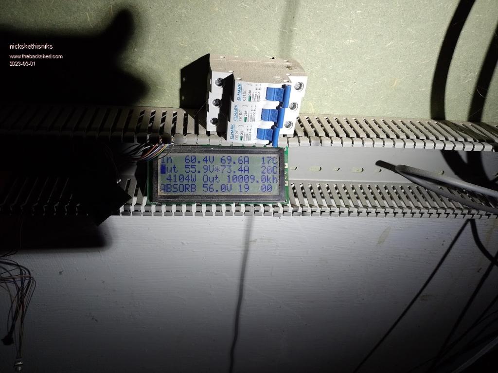 |
||||
