
|
|
Forum Index : Electronics : driving via canbus Eltek 2kW Flatpack2 supplies
| Author | Message | ||||
| poida Guru Joined: 02/02/2017 Location: AustraliaPosts: 1387 |
I think something that isolates the canbus differential pair so that any potential difference between power supply and system ground can be used. I would like a bidirectional differential chip. 2 pins on isolated side, 2 on system ground side. It needs to permit either side to drive diff high or diff low signals This scheme would need only one canbus controller (MCP2515 which is what I prefer to use due to functional code I have). An uglier way would have a MCP2515 or similar controller running at the local grounds of each power supply. These would need local ground referenced 5V supply too. Then take the SPI signals and isloate them, connecting to the Nano. Each power supply needs it's own chip select. The Arduino canbus software can run multiple instances of the CAN object. I don't want to go that way unless at gun-point. Series connection of these supplies gives a limited range of output voltages. N x 43V as a minimum, N x 57.3V as a max. where N = number of supplies. wronger than a phone book full of wrong phone numbers |
||||
| poida Guru Joined: 02/02/2017 Location: AustraliaPosts: 1387 |
Further, the MCP2515 module I use has the TJA1050 high speed can transceiver which is used to connect the can HIGH and LOW diff pair to local logical 5V TTL. If we removed the TJA1050 and used the ADM2795E it might be what we need. The ADM2795E has 5kV isolation, takes a diff pair for input and gives the same TTL data read and write pins as TJA1050. Or pulse transformers? Will canbus drivers tolerate those as loads? wronger than a phone book full of wrong phone numbers |
||||
| BenandAmber Guru Joined: 16/02/2019 Location: United StatesPosts: 961 |
poida i bought a 150 amp one to use when testing inverters be warned i am good parrot but Dumber than a box of rocks |
||||
| nickskethisniks Guru Joined: 17/10/2017 Location: BelgiumPosts: 409 |
150A 48V ?  |
||||
| BenandAmber Guru Joined: 16/02/2019 Location: United StatesPosts: 961 |
Yes 150 amp and is now set at 52 volts I would like to set it to 60 volts it is a X series be warned i am good parrot but Dumber than a box of rocks |
||||
| poida Guru Joined: 02/02/2017 Location: AustraliaPosts: 1387 |
No, not even close. There has been some progress with code for the parallel of Elteks project. I have two 2kW HE Eltek Power supplies. I can run both as one. The code needs you to put your Eltek 2kW HE serial numbers into the data at the start of the program. Read the label on the PS and copy that 6 byte hex string into the array. Put it into the first 6 bytes of a row. See the byte array named "login" I have left the serials of my 2 PS's in place in the code. Also you have to tell it how many PS are present. look for the line where #define NPS 2 change this to the number of your PS's you have. Wiring is simple. All PS's CAN HIGH are connected to the CAN HIGH input of the MCP2515 module and all CAN LOW are connected to the CAN LOW of the module. All CAN ground are connected together to the MCP2515 module ground. Use the jumper to connect CAN HIGH to CAN LOW with 120 Ohm resistor. It can run up to 4 PS's which means a device that can drive about 160A at 43V to 57V with Constant current or constant voltage control. You start in CV mode, so you rotate the encoder to choose an output voltage. press the button and then choose an output current. (the current will be spread between all available PS's. If you dial up 40 Amps and have two PS's, then each PS will deliver 20 Amps. If you have 4 PS's then each PS will deliver 10 Amps.) The Eltek 2kW HE PS can only drop it's output voltage to about 43V when it is attempting to reduce output current. Once it gets to 43V it does not drop further. This limits how useful the CC mode can be. Also it limits how useful the CV mode is. But it is pretty good fit for Lead Acid battery charging. here is a video: https://youtu.be/Ril49CN12mw You need: 1 x nano 1 x MCP2515 canbus-spi module 1 x good quality rotary encoder 1 x I2C 20 x 4 LCD a bit of hookup wire. The circuit is this (if you build it from descrete parts): Schematic_eltek parallel v1_2021-04-07.pdf.zip The code is this: /* * Nano, Canbus MCP2515, serial LCD, optical rotary encoder (quadrature) * * this can drive 1 to 4 ELtek Flatpack 48V 2kW PS * with a constant voltage control * * Output voltage and current limit is set via encoder. * push button to toggle from CV to CC * * The serial numbers are unique for each PS and must be set for your units * * The outputs of the PSs and the voltage setpoint are available for plotting via Arduino IDE plotter */ #include <SPI.h> #include "mcp_can.h" #include <mcp_can_dfs.h> #include <LiquidCrystal_PCF8574.h> #include <Wire.h> LiquidCrystal_PCF8574 lcd(0x27); unsigned char login[][8] = { {0x16, 0x36, 0x71, 0x07, 0x03, 0x76, 0x00, 0x00}, {0x18, 0x10, 0x50, 0x01, 0x76, 0x09, 0x00, 0x00}, {0x0, 0x0, 0x0, 0x0, 0x0, 0x0, 0x0, 0x0}, {0x0, 0x0, 0x0, 0x0, 0x0, 0x0, 0x0, 0x0}}; #define NPS 2 float v[4],i[4]; volatile int ps_alive[4],nps, icount; MCP_CAN CAN(10); // Set CS pin as D10 #define VOLTAGE 4800 #define CURRENT 450 uint8_t outset[8] = {CURRENT & 0xff, (CURRENT >> 8) & 0xff, VOLTAGE & 0xFF, (VOLTAGE >> 8) & 0xFF ,VOLTAGE & 0xFF, (VOLTAGE >> 8) & 0xFF ,0x3E, 0x17}; float pot,cpot,tamps; char lcdbuf[90],*lp,lpc; void get_biquad(float,int,int); void biquad_filter(float *,int); float aa[5][8],d1[5][8],d2[5][8]; float w0[5][8],w1[5][8],w2[5][8]; int bqnp[8]; void ps_check_send(int , unsigned char *, uint32_t , unsigned int , unsigned int ); volatile int encoderPos = 0,b_mode, opto_v, opto_i; volatile boolean PastA = 0; volatile boolean PastB = 0; volatile long last_press; void doEncoderA() { //PastB ? encoderPos-- : encoderPos++; if (PastB) { if (b_mode == 0) opto_v --; else opto_i --; } else { if (b_mode == 0) opto_v ++; else opto_i ++; } if (opto_v < 0) opto_v = 0; if (opto_i < 0) opto_i = 0; if (opto_v > 100) opto_v = 100; if (opto_i > 100) opto_i = 100; } void doEncoderB() { PastB = !PastB; } void get_biquad(float fc, int np, int idx) { float s,r; int i; float a = tan(M_PI*fc); float a2 = a*a; bqnp[idx] = np; for(i=0; i<np; ++i) { r = sin(3.141592926 * (2.0*i+1.0)/(4.0*(float)np)); s = a2 + 2.0*a*r + 1.0; aa[i][idx] = a2/s; d1[i][idx] = 2.0*(1-a2)/s; d2[i][idx] = -(a2 - 2.0*a*r + 1.0)/s; w1[i][idx]=w2[i][idx]=w0[i][idx]=0.0; } } void biquad_filter(float *val, int idx) { float s; int i; s = *val; for(i=0; i<bqnp[idx]; ++i) { w0[i][idx] = d1[i][idx]*w1[i][idx] + d2[i][idx]*w2[i][idx] + s; s = aa[i][idx]*(w0[i][idx] + 2.0*w1[i][idx] + w2[i][idx]); w2[i][idx] = w1[i][idx]; w1[i][idx] = w0[i][idx]; } *val = s; } void setup() { int n; // optical encoder setup opto_v = 0; opto_i = 0; last_press = millis(); pinMode(2, INPUT); pinMode(3, INPUT); pinMode(8,INPUT_PULLUP); PastA = (boolean)digitalRead(2); //initial value of channel A; PastB = (boolean)digitalRead(3); //and channel B // encoder A channel on interrupt 0 (Arduino's pin 2) attachInterrupt(0, doEncoderA, RISING); // encoder B channel pin on interrupt 1 (Arduino's pin 3) attachInterrupt(1, doEncoderB, CHANGE); b_mode = 0; // = 1 for change current, = 0 for change voltage Serial.begin(115200); lcd.begin(20,4); lcd.print(" ELTEK CV/CC "); pinMode(3,INPUT); pinMode(12,INPUT); START_INIT: if(CAN_OK == CAN.begin(MCP_ANY, CAN_125KBPS, MCP_8MHZ)) { //Serial.println("CAN BUS Shield init ok!"); } else { Serial.println("CAN BUS Shield init fail"); Serial.println("Init CAN BUS Shield again"); delay(1000); goto START_INIT; } icount = 0; CAN.setMode(0); delay(200); nps = NPS; for (n=0; n < nps; n++) { ps_alive[n] = 0; v[n]=i[n]=0.0; } for (n=0;n < (nps*2); n++) get_biquad(0.2,2,n); lp = lcdbuf; lpc=0; memset(lp,' ',80); } void loop() { unsigned char len = 0; unsigned char buf[8] ; int rv, was_msg,n, n_alive; float a; unsigned int ui,uc; uint32_t canId; // look for button press on D8, toggle b_mode. Debounce with 1000 milisecond delay if (digitalRead(8) == 0 && (millis() - last_press) > 1000) // D8 is input with internal pullup. zero = button press { last_press = millis(); if (b_mode == 1) b_mode = 0; else b_mode = 1; } // update LCD a char at a time lcd.write(lcdbuf[lpc]); lpc++; if (lpc > 79) { lpc=0; lcd.home(); delay(100); icount++; if (icount > 5) { icount=0; for (n = 0; n < nps; n++) { CAN.sendMsgBuf(0x05004800 + 4 * (n+1), 1, 8, login[n]); } } } // get pot settings a = (float)opto_v/100.0; // pot is connected to 3.3V so need this scale for 0 - 1 range. 5V pin is used by canbus adaptor pot = 43.0 + (57.4 - 43.0)*a; // set demand from 43 to 57V. flatpack has output limits smaller than this range. if (pot < 43.0) pot = 43.0; if (pot > 57.4) pot = 57.4; // programming more than that makes the canbus program command be ignored so current limit changes will also be ignored ui = int(pot * 100.0); a = (float)opto_i/100.0; // pot is connected to 3.3V so need this scale for 0 - 1 range. 5V pin is used by canbus adaptor cpot = (float)nps*45.0*a; // set current limit if (cpot < 0.0) cpot = 0.0; n_alive=0; for (n=0; n < nps; n++) if (ps_alive[n] == 1) n_alive++; if (n_alive == 0) uc = int( cpot * 10.0/(float)nps ); // none alive else uc = int( cpot * 10.0/(float)n_alive ); // scale current setpoint to (no. of ps alive)/(no. of ps) // check for CAN message and parse was_msg = 0; rv = CAN.checkReceive(); if(rv == CAN_MSGAVAIL ) { was_msg = 1; CAN.readMsgBuf(&len, buf); canId = CAN.getCanId(); for(n=0; n < nps; n++) ps_check_send(n, buf,canId, ui, uc); } do_lcd(); if (was_msg == 1 ) { // for graphing Serial.print (tamps); Serial.print(" "); Serial.print (pot); Serial.print(" "); Serial.print (cpot); Serial.print(" "); for (n=0; n < nps; n++) { Serial.print (v[n]); Serial.print(" ");Serial.print(i[n]);Serial.print(" "); } Serial.println(" 0 60 "); } } void ps_check_send(int ps_n, unsigned char buf[], uint32_t canId, unsigned int ui, unsigned int uc) { int ps_no = ps_n + 1; uint32_t c1,c2,c3; c1 = 0x05004004 + 0x10000 * ps_no; c2 = 0x05004008 + 0x10000 * ps_no; c3 = 0x0500400C + 0x10000 * ps_no; if (canId == c1 || canId == c2 ) { i[ps_n] = buf[2]*255*0.1+buf[1]*0.1; v[ps_n] = buf[4]*255*0.01+buf[3]*0.01; biquad_filter(&v[ps_n],ps_n*2); biquad_filter(&i[ps_n],1 + ps_n*2); //CAN.sendMsgBuf(0x05004800 + 4 * ps_no, 1, 8, login[ps_n]); // make changes to control word with new Vout outset[0] = uc & 0xff; outset[1] = (uc >> 8) & 0xff; outset[2] = outset[4] = ui & 0xff; outset[3] = outset[5] = (ui >> 8) & 0xff; CAN.sendMsgBuf(0x05FF4000 + 4 * ps_no, 1, 8, outset); ps_alive[ps_n] = 1; } if (canId == c3) { ps_alive[ps_n] = 0; i[ps_n] = v[ps_n] = 0.0; } } void do_lcd() { char fbuf[10],hbuf[10],gbuf[10]; int cmode,n,p[4]; p[0] = 0; p[1] = 40; p[2] = 20; p[3] = 60; tamps = 0.0; for(n=0; n < nps; n++) tamps += i[n]; if ( (cpot - tamps) < 1.0) cmode = 1; else cmode = 0; dtostrf(pot,4,1,gbuf); dtostrf(cpot,5,1,fbuf); dtostrf(tamps,5,1,hbuf); if (cmode == 1) sprintf(&lcdbuf[16],"CC "); else sprintf(&lcdbuf[16],"CV "); sprintf(&lcdbuf[35],"%4s ",gbuf); sprintf(&lcdbuf[54],"%5s ",fbuf); sprintf(&lcdbuf[74],"%5sA",hbuf); if (b_mode == 0) { lcdbuf[39] = 'v'; lcdbuf[59] = 'A'; } else { lcdbuf[39] = 'V'; lcdbuf[59] = 'a'; } for (n=0; n < 4; n++) { if (ps_alive[n] == 1) { dtostrf(v[n],4,1,fbuf); dtostrf(i[n],4,1,hbuf); sprintf(&lcdbuf[p[n]],"%d %4sV %4sA",n+1,fbuf,hbuf); } else { if (n < nps) sprintf(&lcdbuf[p[n]],"%d 0.0V 0.0A",n+1); else sprintf(&lcdbuf[p[n]],"%d ",n+1); } lcdbuf[p[n]+ 13] = ' '; } } wronger than a phone book full of wrong phone numbers |
||||
| Aleksa Newbie Joined: 18/06/2021 Location: YugoslaviaPosts: 8 |
Hi, Litle (BIG)help? According the Arduino monitor CAN bus voltage preset procedure works properly (https://github.com/The6P4C/Flatpack2), but supply doesn't change the voltage into the value defined by arduino scatch (48.00V, 4800 value of register), even upon supply reboot with switch-off interval of more then few minutes. Does he have any idea what was done wrong? ------------------- 10:07:25.302 -> Entering Configuration Mode Successful! 10:07:25.302 -> Setting Baudrate Successful! 10:07:25.302 -> MCP2515 initialized successfully. 10:07:40.544 -> ID: 0x05014400 Length: 8 Data: 0x07 0x10 0x71 0x00 0x96 0x09 0x00 0x00 10:07:53.282 -> ID: 0x05001609 Length: 8 Data: 0x1C 0x07 0x10 0x71 0x00 0x96 0x09 0x00 10:07:53.282 -> Starting set 10:07:53.282 -> Set completed 10:07:53.282 -> ID: 0x05001609 Length: 8 Data: 0x1B 0x07 0x10 0x71 0x00 0x96 0x09 0x00 10:07:53.282 -> ID: 0x05001609 Length: 8 Data: 0x1B 0x07 0x10 0x71 0x00 0x96 0x09 0x00 10:07:53.572 -> ID: 0x05001609 Length: 8 Data: 0x1B 0x07 0x10 0x71 0x00 0x96 0x09 0x00 10:07:55.611 -> ID: 0x05001609 Length: 8 Data: 0x1B 0x07 0x10 0x71 0x00 0x96 0x09 0x00 10:07:55.891 -> ID: 0x05014400 Length: 8 Data: 0x07 0x10 0x71 0x00 0x96 0x09 0x00 0x00 10:07:57.652 -> ID: 0x05001609 Length: 8 Data: 0x1B 0x07 0x10 0x71 0x00 0x96 0x09 0x00 10:07:59.701 -> ID: 0x05001609 Length: 8 Data: 0x1B 0x07 0x10 0x71 0x00 0x96 0x09 0x00 10:08:01.751 -> ID: 0x05001609 Length: 8 Data: 0x1B 0x07 0x10 0x71 0x00 0x96 0x09 0x00 10:08:03.832 -> ID: 0x05001609 Length: 8 Data: 0x1B 0x07 0x10 0x71 0x00 0x96 0x09 0x00 10:08:05.871 -> ID: 0x05001609 Length: 8 Data: 0x1B 0x07 0x10 0x71 0x00 0x96 0x09 0x00 10:08:07.911 -> ID: 0x05001609 Length: 8 Data: 0x1B 0x07 0x10 0x71 0x00 0x96 0x09 0x00 10:08:09.962 -> ID: 0x05001609 Length: 8 Data: 0x1B 0x07 0x10 0x71 0x00 0x96 0x09 0x00 10:08:11.271 -> ID: 0x05014400 Length: 8 Data: 0x07 0x10 0x71 0x00 0x96 0x09 0x00 0x00 10:08:11.991 -> ID: 0x05001609 Length: 8 Data: 0x1B 0x07 0x10 0x71 0x00 0x96 0x09 0x00 10:08:14.071 -> ID: 0x05001609 Length: 8 Data: 0x1B 0x07 0x10 0x71 0x00 0x96 0x09 0x00 10:08:16.119 -> ID: 0x05001609 Length: 8 Data: 0x1B 0x07 0x10 0x71 0x00 0x96 0x09 0x00 10:08:18.141 -> ID: 0x05001609 Length: 8 Data: 0x1B 0x07 0x10 0x71 0x00 0x96 0x09 0x00 10:08:20.220 -> ID: 0x05001609 Length: 8 Data: 0x1B 0x07 0x10 0x71 0x00 0x96 0x09 0x00 Thanks in advance 73 Aleksandar |
||||
| poida Guru Joined: 02/02/2017 Location: AustraliaPosts: 1387 |
Hi Alexandar I can not make much sense from the above information printed to the serial console. here is my code for setting the Eltek voltage. It worked and programmed 4 different 2Kw units. I think it would be best if we compare the data you get out of yours with what we would expect with the below code. One thing to look out for is to use the correct ID number in the command word. #include <SPI.h> #include "mcp_can.h" #include <mcp_can_dfs.h> // first unit unsigned char login[8] = {0x16, 0x36, 0x71, 0x07, 0x03, 0x76, 0x00, 0x00}; //this is for logging into your flatpack. Must use your serial number. const int SPI_CS_PIN = 10; MCP_CAN CAN(SPI_CS_PIN); // Set CS pin #define VOLTAGE 4800 #define CURRENT 450 uint8_t outset[8] = {CURRENT & 0xff, (CURRENT >> 8) & 0xff, VOLTAGE & 0xFF, (VOLTAGE >> 8) & 0xFF ,VOLTAGE & 0xFF, (VOLTAGE >> 8) & 0xFF ,0x3E, 0x17}; volatile int got_cb_data = 0; // 0x1130 = 44.00V // 0x12C0 = 48.00V // 0x1680 = 57.60V // low byte first {0x29, 0x15, 0x00, 0x30, 0x11}; unsigned char setdefaultvolt[5] = {0x29, 0x15, 0x00, 0xc0, 0x12}; float potvolts; void setup() { Serial.begin(115200); pinMode(3,INPUT); pinMode(12,INPUT); START_INIT: if(CAN_OK == CAN.begin(MCP_ANY, CAN_125KBPS, MCP_8MHZ)) { Serial.println("CAN BUS Shield init ok!"); } else { Serial.println("CAN BUS Shield init fail"); Serial.println("Init CAN BUS Shield again"); delay(1000); goto START_INIT; } CAN.setMode(0); delay(200); CAN.sendMsgBuf(0x05004804, 1, 8, login); // id = 1 so XX = 04 delay(200); CAN.sendMsgBuf(0x05019C04, 1, 5, setdefaultvolt); } void loop() { } Near the end of the code is CAN.sendMsgBuf(0x05004804, 1, 8, login); // id = 1 so XX = 04 Since is this the first time a device has sent data to the Eltek, an ID number needs to be established and used from then on in any further commands. I use the ID = 1, and it is represented as 0x04 in the last 8 bits of the "login" command. Then the command to set the voltage is sent, using the ID number as seen in the lowest 8 bits of the second message send call My code does not very much at all, starts the canbus interface and logs in to the Eltek, sends one command and then loops doing nothing. To use it, I ensure the unit's serial number is present in the login[8] array. choose a voltage, and do it. The canbus interface needs 3 wires, canhi, canlow and ground. maybe check the signals of canhi and canlow with an oscilloscope to ensure good and fast rise and fall times. The terminating resistors are important. When I did not use them on the SPI-can module, communication was nearly impossible. This might not solve things immediately but it is a start point. Also, have a look at the attached file, it is the protocol that has been reverse engineered by someone on endlessphere. Can Protocol.zip wronger than a phone book full of wrong phone numbers |
||||
| Aleksa Newbie Joined: 18/06/2021 Location: YugoslaviaPosts: 8 |
Good mornining, Thanks for quick answer, I am not an expert in this field, so I asked a colleague from work to help me. I will give him this answer and he will understand what he needs to do. I call as soon as I get information from him. Aleks |
||||
| Aleksa Newbie Joined: 18/06/2021 Location: YugoslaviaPosts: 8 |
Hi, Attached is a sticker from my power supply. What is a serial number here, because there are more numbers that look like SN 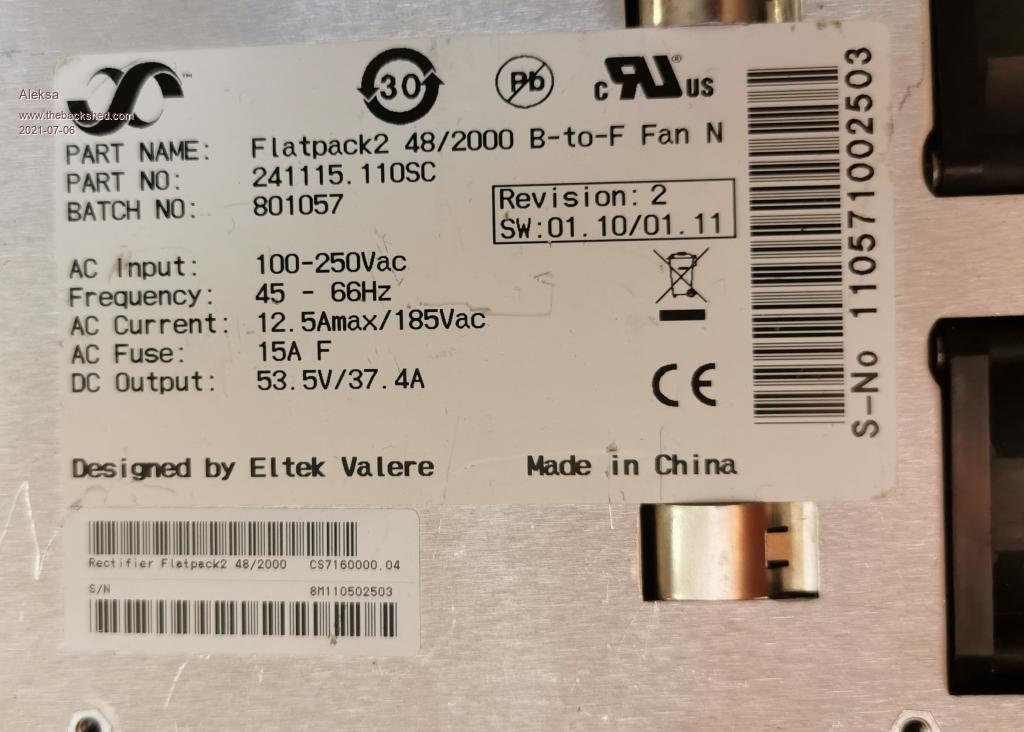 |
||||
disco4now Guru Joined: 18/12/2014 Location: AustraliaPosts: 843 |
The serial no is next to the vertical barcode in you picture. Take the digits 2 at a time to give you the first 6 hex numbers, then add two 0x00 to make up the rest. So I think it should be: unsigned char login[8] = {0x11, 0x05, 0x71, 0x00, 0x25, 0x03, 0x00, 0x00}; Latest F4 Latest H7 |
||||
| Aleksa Newbie Joined: 18/06/2021 Location: YugoslaviaPosts: 8 |
Thanks, Forwarded to my colleague  |
||||
| Aleksa Newbie Joined: 18/06/2021 Location: YugoslaviaPosts: 8 |
Hi, Hi, my colleague noticed that the program could not be compiled and asked where is the whole program for changing the voltage? 73 Aleksa |
||||
| poida Guru Joined: 02/02/2017 Location: AustraliaPosts: 1387 |
install this library MCP_CAN_lib-master.zip and it should work. Edited 2021-07-08 08:28 by poida wronger than a phone book full of wrong phone numbers |
||||
| Aleksa Newbie Joined: 18/06/2021 Location: YugoslaviaPosts: 8 |
Hi poida, This is from my colleague: " There is a problem with number of arguments in your program: CAN.readMsgBuf(&len, buf); In comparison to library's function readMsgBuf(INT32U *id, INT8U *len, INT8U buf[]) " Please advice what to do next? 73 Aleksa |
||||
| poida Guru Joined: 02/02/2017 Location: AustraliaPosts: 1387 |
Aleksa I'm not sure what is going on, and what you are attempting to do. First, I want to confirm that you want to program a 2kW Eltek with a new output voltage, and to have this retained permanently. Is this so? Next, I want to know what program you are using to do this. Is it the code at https://github.com/The6P4C/Flatpack2) or is it my code, that I showed in the post here If you are using my code, then all I can do is say again get the MCP_CAN library I used with my code and do not have other CAN libraries installed. And then use my small program to set the output voltage. Put the Eltek's serial number in the data array. choose your output voltage or work out the hex value for a different one, run the program and unpower the unit and wait a couple of minutes. Check output when you power it up again. My program only makes 3 calls to functions in the library after the CAN object was initialised and then communication settings were defined. CAN.setmode(), then CAN.sendMsgBuf(0x05004804, 1, 8, login) with the 4 parameters and lastly CAN.sendMsgBuf(0x05019C04, 1, 5, setdefaultvolt) again with 4 parameters Nowhere does my code call CAN.sendMsgBuf(..) with only 2 parameters such as you wrote "CAN.readMsgBuf(&len, buf);" I am thinking there is some confusion between us as to which page we are reading the story from. wronger than a phone book full of wrong phone numbers |
||||
| Aleksa Newbie Joined: 18/06/2021 Location: YugoslaviaPosts: 8 |
Thanks poida, I forwarded your answer to my colleague. I hope everything will be fine now? Best regards Aleksandar |
||||
| Aleksa Newbie Joined: 18/06/2021 Location: YugoslaviaPosts: 8 |
Hi, poida My colleague went on vacation, I have to wait 2 weeks, minimum  |
||||
| Tinbum Newbie Joined: 12/08/2021 Location: United KingdomPosts: 4 |
I'm also getting the same message when I try to compile. no matching function for call to 'MCP_CAN::readMsgBuf(unsigned char*, unsigned char [8])' It's highlighting; // check for CAN message and parse was_msg = 0; rv = CAN.checkReceive(); if(rv == CAN_MSGAVAIL ) { was_msg = 1; CAN.readMsgBuf(&len, buf); canId = CAN.getCanId(); for(n=0; n < nps; n++) ps_check_send(n, buf,canId, ui, uc); } I've installed the library you linked to. |
||||
| Tinbum Newbie Joined: 12/08/2021 Location: United KingdomPosts: 4 |
To answer my own question I found this; The readMsgBuf() functions bring in the message ID. The getCanId() function is obsolete and no longer exists, don't use it. The readMsgBuf(*ID, *DLC, *DATA) function will return the ID type (extended or standard) and it will bring back the remote request status bit. If the ID AND 0x80000000 EQUALS 0x80000000, the ID is of the Extended type, otherwise it is standard. If the ID AND 0x40000000 EQUALS 0x40000000, the message is a remote request. The readMsgBuf(*ID, *EXT, *DLC, *DATA) function will return the ID unaltered and doesn't inform us of a remote request. If EXT is true, the ID is extended. So the sketches need a little bit of altering. |
||||
