
|
|
Forum Index : Electronics : driving via canbus Eltek 2kW Flatpack2 supplies
| Author | Message | ||||
| nickskethisniks Guru Joined: 17/10/2017 Location: BelgiumPosts: 411 |
Someone knows if I can use these psu's straight from solar panels? They have a wide AC (DC?) input range, and with some trickery I could make a HV solar charger out of them. I would put a (poida) mppt controller behind it, sense solar voltage with an isolated opamp or hall sensor-ish sensor. |
||||
| wiseguy Guru Joined: 21/06/2018 Location: AustraliaPosts: 995 |
Nick, that is how I would do it, keep the solar PV power at the "sweet spot" and charge as much as possible whilst maintaining the sweet spot. Just make sure the panel's open circuit voltage doesn't exceed the Flatpack2's 300VDC max input voltage. I have proved with a variac and crude transformer/rectifier/capacitor setup that they will operate fine from a DC input. If at first you dont succeed, I suggest you avoid sky diving.... Cheers Mike |
||||
| nickskethisniks Guru Joined: 17/10/2017 Location: BelgiumPosts: 411 |
Thanks! |
||||
| KENSTV Newbie Joined: 12/01/2023 Location: United StatesPosts: 5 |
Does anybody have page 2 of the schematic for the flatpack 2 48V HE, I found an 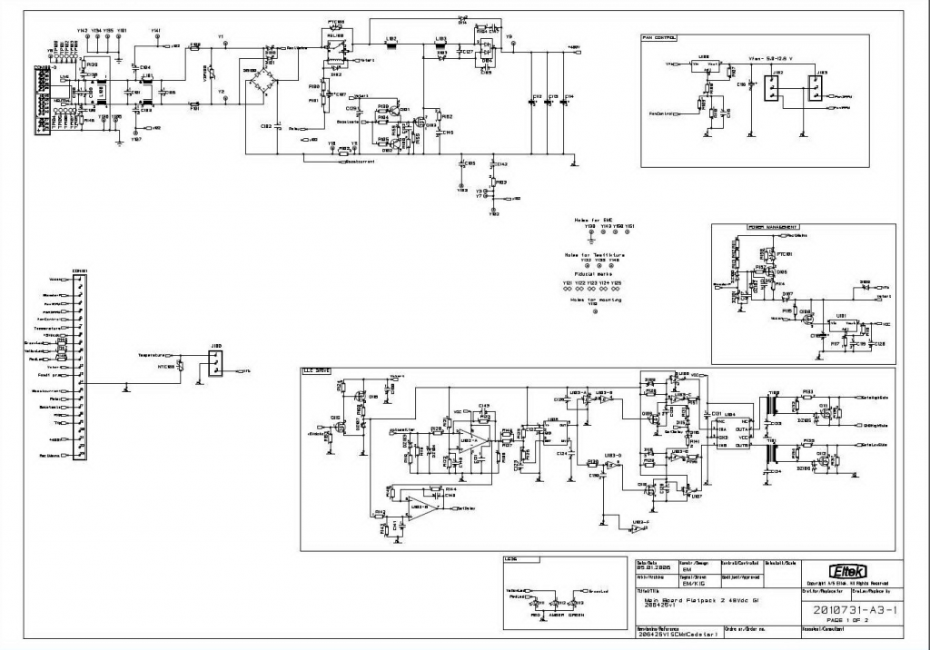 official eltek schematic for the main board but its only page one  even better would be the standup control board schematic, Wiseguy did send some schematics but they are for the original flatpacks which have a totally different control setup, even though these can be programmed I want to just modify the circuit to output a different voltage all the time at plug in after the soft start, it turns out the control of the flatpack 2 HE is done with a ML56F8037T microcontroller, my plan is to just alter the resistance on the voltage sample back to the micro A-D converter thus tricking into thinking the output voltage is the code set 53.5V, there are 4 resistors on the output voltage and current tracking-going back to the microcontroller on the standup board one of these should alter the sample of the output voltage, so page 2 would be nice even better would be the standup control board schematic, Wiseguy did send some schematics but they are for the original flatpacks which have a totally different control setup, even though these can be programmed I want to just modify the circuit to output a different voltage all the time at plug in after the soft start, it turns out the control of the flatpack 2 HE is done with a ML56F8037T microcontroller, my plan is to just alter the resistance on the voltage sample back to the micro A-D converter thus tricking into thinking the output voltage is the code set 53.5V, there are 4 resistors on the output voltage and current tracking-going back to the microcontroller on the standup board one of these should alter the sample of the output voltage, so page 2 would be niceNote these supply's are very high end and the control circuitry is very complex, and the parts scale is almost microscopic as well as the multi layered boards all add to the difficulty of hacking the circuit but I think it is the easiest way to get a different output voltage without all the code, Arduino and CAN interface board Also the Thai mod is for the original analog control flatpacks, the flatpack 2 HE use microcontrollers for front end monitoring and output control, there are 2 microcontrollers !! |
||||
| poida Guru Joined: 02/02/2017 Location: AustraliaPosts: 1388 |
you want 53.5V? Can do this with no hardware hacking, just sending modbus commands. One nano, one canbus module and it will be done. If you need a little help with this I will help you. It's no biggie. wronger than a phone book full of wrong phone numbers |
||||
| KENSTV Newbie Joined: 12/01/2023 Location: United StatesPosts: 5 |
Thanks Poida, not being a coder or not having played with the Arduino Nano I could use the help ! my questions are: 1-can you link to the files used on the Arduino-SPI to run the code, and does the SPI interface provide the 60 ohm termination on the CAN lines? 2-Is it possible to program the Flatpack 2 HE--version one--to keep the voltage setup code after power down? 3-does your code automatically read out the serial number or do I have to first discover the internal serial number and add it to the code? 4-I'm needing 50 volt output, what would the code be for that voltage be? Also I've noticed that both of the microcontrollers have SPI interfaces on both of those standup boards edges, which makes me think the parameters are setup at build and the firmware is possibly not locked down in both those chips, or at least there are ways to get into the firmware according to the data sheets-if it helps to understand the workings of these complex supply's the main output control micro is a MC56F8037V and the smaller front end micro is a MC56F8014 (I believe it monitors input voltage and controls the fan) which are both Freescale products (bought by NXP) and 56F802X and 56F803X Peripheral Reference Manual is available detailing the main microprocessor setup--- |
||||
| poida Guru Joined: 02/02/2017 Location: AustraliaPosts: 1388 |
Hi Kenstv firstly, I have not played with these for a while so there will be some errors in what I can remember. Parts used: a cheap Chinese Nano, using the CH340 serial-USB chip CH340 driver for Windows: CH34x_Install_Windows_v3_4.zip a MCP2515 CAN to SPI module 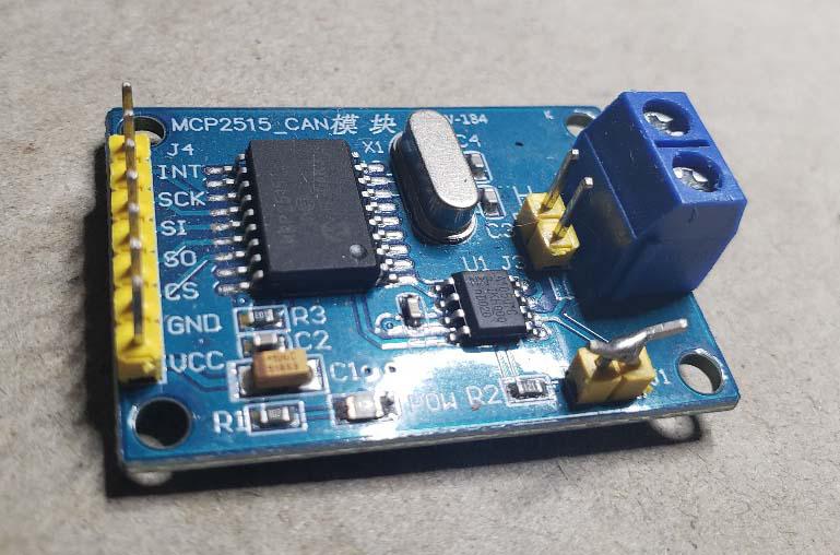 software: Arduino programming package, (called the IDE), I prefer the legacy version 1.8.19 CAN - SPI board library, I upload below. MCP_CAN_lib-master.zip the program to load into the nano: Eltek_set_perm_voltage.zip howto: install Arduino IDE add a library, in the form of a .zip file. Add the MCP_CAN lib above install CH34X driver. plug in nano, prove you can load and run programs. Usually you need to choose " ATmega328 (old bootloader)" as the processor connect the MCP2515 module to the nano. 6 wires. ground, 5V and the 4 SPI, chip select, clock, MISO, MOSI The program has the SPI to nano pin info inside it. The guts of the program is to send one modbus command. .. unsigned char setdefaultvolt[5] = {0x29, 0x15, 0x00, 0xc0, 0x12}; .. CAN.sendMsgBuf(0x05019C04, 1, 5, setdefaultvolt); .. The last two bytes of setdefaultvolt is the voltage we want, low byte first. 0xc0 and 0x12 so the default voltage value is 0x12c0 converting this to decimal is 4800 and that is the voltage in hundredths of a volt. For the program to make the Eltek work at all, it must first "login" using the serial number. This is found on the label of the flatpack. mine looks like: 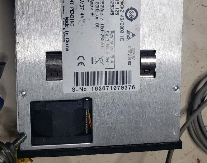 you use the serial number as part of the login process. .. unsigned char login[8] = {0x16, 0x36, 0x71, 0x07, 0x03, 0x76, 0x00, 0x00}; .. CAN.sendMsgBuf(0x05004804, 1, 8, login); � �// id = 1 so XX = 04 � .. of course your serial number will be different so you need to edit the program to suit. And change the default volts to what you need. Once you have made the changes to the code, upload it. power up the flatpack, note the output voltage. press the reset button on the nano, this will run the program and then stop. IMPORTANT: remove power from the flatpack and wait 20 seconds. This lets the canbus system in the flatpack to finally stop running. reapply power and you will see the new output voltage. my janky setup I just did 10 minutes ago to verify all this 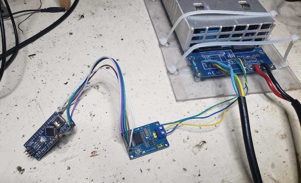 you MUST connect Eltek's CANBUS signal ground to the MCP2515 ground. MUST, or you will blow the MCP2515 module. I think that's what happens, maybe nothing at all. I forget. I connect the ground to the Eltek CANBUS signal ground answers to questions: see above for code needed. You link two pins on the MCP2515 board as seen in the photo to get the resistor termination needed. NO link and it will not work. It is possible to program a new voltage that is retained over power cycles My code does not auto read the serial, I am too lazy to bother with this. The code does the job, just read the label and change the code.. 50 V = 5000 hundredths = 0x1388 remember to reverse theses 2 bytes in setdefaultvolt array I feel I've done the whole job for you. Edited 2023-01-26 09:10 by poida wronger than a phone book full of wrong phone numbers |
||||
| KENSTV Newbie Joined: 12/01/2023 Location: United StatesPosts: 5 |
Thank you, straight and to the point, I have the boards ordered |
||||
| poida Guru Joined: 02/02/2017 Location: AustraliaPosts: 1388 |
and a bonus, I found more schematics FlatPack2_Schem.png.pdf wronger than a phone book full of wrong phone numbers |
||||
| KENSTV Newbie Joined: 12/01/2023 Location: United StatesPosts: 5 |
Worked like a champ on my version 1 firmware Poida  thanks for stopping me from moding it, I have extensive skills and equipment for soldering and rework but the lead free solder on these flatpacks needs a lot of heat which would have been difficult on those control board pins, I'm sure I could have just changed the feedback voltage sample to the microcontroller but the time to program instead makes more sense thanks for stopping me from moding it, I have extensive skills and equipment for soldering and rework but the lead free solder on these flatpacks needs a lot of heat which would have been difficult on those control board pins, I'm sure I could have just changed the feedback voltage sample to the microcontroller but the time to program instead makes more senseOne thing I notice is the red beacon symbol led now is flashing like the flatpack is trying to comm with the controller, the manual says the red led is "Alarm LED is ON (shutdown or similar major alarm)" I don't remember the red led on at initial plugin maybe the flatpack wants a ID number assigned, not sure if the code did that or not ? Another thing is the fan is hellishly loud-I will just lower the voltage to it with a resistor BTW the 4 wire fan provides feedback to the micro that it is spinning, the extra 2 wires just go to a hall sensor, I doubt the micro counts pulses, it most likely looks for lack of pulses Thanks again  Edited 2023-02-02 07:13 by KENSTV |
||||
| Sinar Newbie Joined: 10/07/2023 Location: RomaniaPosts: 4 |
Hello, I am a radio amateur from Romania and I would like to use the power supply Flat Pack2 (48v-2000W) for a power amplifier. However, the default voltage is too high and I would like to change it. Please tell me specifically how to connect the can transceiver to the flatpack2. Can HI and can LOW is clear, but where is the ground (GND) of the transceiver connected? At the -DC output of flatpack2 or to GND of the CAN bus? Thank you in advance, Romeo - YO8RAW |
||||
| KENSTV Newbie Joined: 12/01/2023 Location: United StatesPosts: 5 |
Ground for the can bus and the DC- are one and the same, just look at the foil of the board, the voltage will only go so low, I think 42V was the lowest, can't find my notes maybe someone else can remember the lowest programmable voltage, one thing to remember these power supply's are very noisy due to the fan design, if not running at a higher amperage you could put a quieter fan in that does not move as much air, the power supply is very efficient and does not heat up much at smaller loads, the noise is high pitched and un-bearable unless in a remote shed like a cell tower building !! |
||||
| Sinar Newbie Joined: 10/07/2023 Location: RomaniaPosts: 4 |
Thanks for the quick response. The board for power supply connections is made by me, but it gives me access to the power supply contacts - anyway, after changing the output voltage, I don't use it anymore because I soldered wires inside. I measured the resistance between -DC and GND CAN BUS and it is very high (infinite). I don't know how the connection boards on ebay are made, but reading on several forums, I'm a bit confused. I tried to program the source (actually not me, I asked a friend, I'm not good at programming) and I connected -DC with GND CAN BUS and with GND transceiver CAN BUS, but I failed to communicate with the source. The message was: "can bus shield init fail" and I thought that I did something wrong on the hard side (connections). Maybe the CAN BUS transceiver is defective. I ordered another one and I'm waiting for it to arrive. I will try again, maybe I will succeed. Thank you Romeo Sorry, I'm using google translate. |
||||
| nickskethisniks Guru Joined: 17/10/2017 Location: BelgiumPosts: 411 |
I made boards with separate ground, but made provision for a resistor to the power ground, uC and transceiver are fed with an isolated powersupply in my situation, but there is no connection between the 2 grounds. I think I read somewhere that it is best to connect power and can bus to the same ground, maybe with a small resistor between the 2 if you are Running a few in parallel. Edited 2023-07-13 19:09 by nickskethisniks |
||||
| Sinar Newbie Joined: 10/07/2023 Location: RomaniaPosts: 4 |
nickskethisniks I will only use one power supply for my application, but I didn't really understand what you mean. If I'm not asking too much, please draw a diagram of the connections you used. For now, I don't have any problems regarding the noise of the fan, for me the power supply will not work in maximum mode all the time. |
||||
| Ziki_the Newbie Joined: 13/04/2023 Location: YugoslaviaPosts: 28 |
Now when you all talking about this. Is it posible to use it on eltek psr 327? Look like older flat pack I have 4pcs 48V 56A 2.7KW in garage, so to add some adjustment is not bad idea. They could be used for some testing.. Pozdrav iz Srbije |
||||
| Sinar Newbie Joined: 10/07/2023 Location: RomaniaPosts: 4 |
Carefully following the instructions on this forum (page 4), I finally managed to adjust my Flat pack to the desired voltage. Thank you. |
||||
| Arthur_Dent Newbie Joined: 18/07/2023 Location: United KingdomPosts: 5 |
Hello, Has anyone had experience load sharing with the Eltek Flatpack 2HE Front End? (i.e. running two rectifiers in parallel for redundancy, etc.) I have a couple of the Flatpack2 Front End Rectifiers with FCI/Berg style connector. One of the pins is ISHARE, which apparently: "Systems use the CAN bus to load share digitally." (from Eltek Document 2127557, Issue 1 Published 17-May-12) V series Rectifier documentation (from 2018) expands a little upon this: "All rectifiers ISHARE pins are tied together on the system backplane to support load sharing. This connection may be terminated between rectifiers or left un-terminated in systems where load share is not required." Does anyone know how this works ? Thanks in advance. |
||||
| poida Guru Joined: 02/02/2017 Location: AustraliaPosts: 1388 |
no idea about the CAN bus share I have run them in parallel and they work as expected. One or the other unit will deliver power up to it's current limit, then the other one will chime in, to deliver power up to it's limit. It's nearly impossible to have both share the load exactly. One will detect the output voltage and go CV before the other. I ran them in series too, the outputs are isolated from the mains AC input so there is no issue. But the CAN bus ground and signals must not be connected together when running them in series. 115V DC at 45 Amps is a power supply with consequences. wronger than a phone book full of wrong phone numbers |
||||
| Arthur_Dent Newbie Joined: 18/07/2023 Location: United KingdomPosts: 5 |
Hi poida Thanks for this. I guess that would work for me. However, I'm still curious as to how the ISHARE feature works if anyone knows? |
||||
